Research Journal
Volume 9, No. 28, Dec. 2015, pages 89–95
DOI: 10.12913/22998624/60792 Research Article
Received: 2015.09.21 Accepted: 2015.11.14 Published: 2015.12.04
ANGULAR POSITIONING ACCURACY OF ROTARY TABLE AND
REPEATABILITY OF FIVE-AXIS MACHINING CENTRE DMU 65 MONOBLOCK
Jerzy Józwik1, Marek Czwarnowski2
1 Department of Production Engineering, Mechanical Engineering Faculty, Lublin University of Technology,
Nadbystrzycka Str. 36, 20-618 Lublin, Poland, e-mail: [email protected]
2 The State School of Higher Education in Chelm, Institute of Technical Sciences and Aviation, 22-100 Chelm,
Center for the Study of Engineering, Depułtycze Królewskie 55, e-mail: [email protected]
ABSTRACT
The study aims to evaluate angular positioning accuracy and repeatability of DMU 65 monoBLOCK numerically controlled machine tool. The measurements were carried out with XL-80 Laser Interferometer with XR20-W attachment. The measurements were conducted according to the standard PN-ISO230-2. Test methodology and
mea-surement results analysis are presented in a form of figures and tables. The final part
presents conclusions from the analysis.
Keywords: positioning, diagnostics, accuracy, CNC machine tool, laser interferometer
INTRODUCTION
Simultaneously with advances in subtrac-tive machining technologies the dimensional and shape accuracy requirements for the components produced with CNC machine tools increase. The quality of finished products depends on, inter alia, positioning accuracy and repeatability of numeri-cally controlled axes, linear and angular errors (and their measurements), axes alignment (assem-bly errors), or backlash in the servo drive (opera-tional errors). Each inaccuracy of the machine is reflected in the final quality of the product [1–4].
In recent years, five-axis machine tools have become widely popular in production processes. This is because of growing capabilities of such machine tools in performing increasingly complex motions and in machining complicated shapes. Most of such machines are used in aircraft and automotive industries, where five-axis machine tools enable producing components of complicat-ed geometry, such as: turbine blades, generators, geometrically intricate car or aircraft elements,
etc. Realisation of complex machining motions requires multi-axis CNC machine tools with not only linear axes but with rotational axes as well.
The most widespread realisation of a rotary axis in CNC machines, without which it would be impos-sible to produce the mentioned components, are rotary or swivel rotary tables, frequently included in the machine tool as a complementation of a lin-ear axis. Usually the rotary axes are parallel to se-lected linear axes of the machine tool; however, in certain machine tools the rotary axis is situated at a 45° angle to one of the linear axes of the machine. Rotary axes in machining centres do not have to be essentially connected with the table. In certain ma-chine tools the design solutions enable the spindle axis to realise motions independently of the square table of the machine [4–6].
of a rotary axis with relation to linear axes, deter-mination of actual rotary axis and the evaluation of stability axis centre [7–12].
One of the most popular methods of rotary axis positioning error measurement is the method employing a laser interferometer with an attach-ment enabling measureattach-ment of rotary axes. This method is applied according to standard ISO 230-2 [13]. The interferometer attachment performs motions following the changes of rotary axis angular position in the opposite direction to the rotary motion of the table. The motion is set to maintain the measuring angle between the laser beam and the rotary table. The error is effectively the difference between the target position, deter-mined by the laser system, and the actual angu-lar position of the tested axis of a machine. This method enables verification of axis positioning accuracy, which is of great importance for com-ponent machining. The analysis of error char-acteristics enables verification of the sources of these errors (in the majority of cases an imprecise rotary angle encoder or its improper mounting [12]). The precision of the interferometric method is ±0.5’’ [14–15].
TEST CONDITIONS AND METHODOLOGY
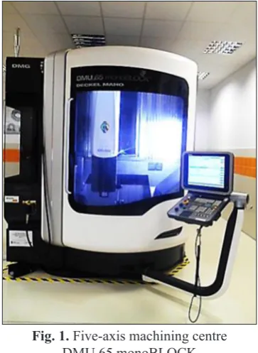
The conducted tests aimed to measure the angular positioning accuracy and repeatability of C axis of a vertical machining centre CMU 65 monoBLOCK (Fig. 1). The tested machine tool is
used in piece production and in didactic process. The measurements were carried out according to international standard PN-ISO 230-2, describing norms for determination of geometric accuracy of machine tools for the machining of metals. The measurements were performed with XL-80 La-ser Interferometer (Fig. 2) equipped with a rotary axis calibrator attachment XR20-W (Fig. 3). The measurements provided data on errors critical to the dimensional and shape accuracy of produced components.
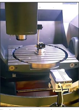
The diagnostic and measurement process is preceded by a series of setting and regulation procedures. At the first stage of these setting and regulation procedures, the XR20-W calibrator is located precisely on the rotary axis of the table (Fig. 4). Next, the angular retroreflector is mount -ed on the magnetic base. XR20-W calibrator is wirelessly connected with the software via Blue-tooth interface.
Fig. 2. Laser Interferometer XL-80 (Renishaw)
Fig. 3. Rotary axis calibrator XR20-W (Renishaw) Fig. 1. Five-axis machining centre
In preparation for the C axis positioning ac-curacy measurement the machine tool table was programmed to perform a rotary motion at α=30° steps at the full rotation scope 360° (Fig. 5). A 4 sec interval was at every discreet measurement posi-tion (at every 30°), during which time the angular position measurement was recorded and captured. After a full revolution, the table moved in the op-posite direction (30° step size, 4 sec interval) until the initial target position was reached. Each test included three measuring cycles. In order to deter-mine the measurement repeatability the tests were repeated 6 times in identical conditions.
TEST RESULTS
Measurement and analysis of test results was conducted with XCal-View 2.1. Obtained measurement data is shown in a form of tables
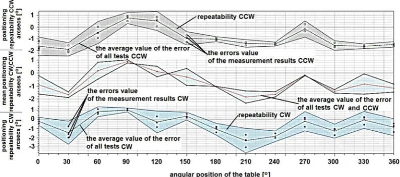
and figures. The computer programme generated curves showing deviations as a function of angu-lar position of the table, and their mean values in each repetition (3 cycles) are shown in Figures 6 and 7. They show a typical graphical representa -tion of the unconverted measurement data (before any analytical formatting), according to the stan-dard ISO-230-2.
Table 1 and Table 2 show detailed statisti-cal data and result analysis for three repetitions of 360° in set directions (CW and CCW) (as ex-amples of results obtained in tests 1 and 2).
Table 3 and Table 4 show selected errors measured in tests. All measurement results are presented with a cyclometric function expressed
in arcsecs. The combination of XR20-W and
la-ser interferometer allows measurement accuracy within ± 1arcsec, which corresponds to a dis-placement of less than 5 mm at a distance of 1 m).
Fig. 5. Preparation for and measurement of positioning errors
Fig. 6. Positioning and repeatability errors (test 1) Fig. 4. Setting XR20-W calibrator and mounting
Fig. 7. Positioning and repeatability errors and deviations with rotation direction (CW; CCW) of C axis (test 1)
Table 1. Measurement results statistics (test 1)
Table 3. Measurement results analysis (test 1)
Figure 8 shows results of all conducted tests. The presented characteristics indicate that angu-lar positioning error [A] of C axis is very small, between 5÷5.9 arcsecs (deviation s = 0.468 arc-secs). The remaining measured error values are even lower. Positioning repeatability [R] of the C axis and systematic deviation [E] are approxi -mately 3 arcsecs. Error return [B] was registered at 1.6÷1.7 arcsecs whereas average return error
0.3÷0.4 arcsecs. Average deviation [M] values were recorded within 2.5÷2.7 arcsecs.
Figure 9. Shows average values of positioning error [A] in all conducted measurements (6 tests) both in positive and negative direction, as a func-tion of angular posifunc-tions of the table (at α=30°).
Figure 10 shows a summary of average values of positioning accuracy, errors and de-viations obtained in all tests and repetitions, in
Fig. 8. Comparative analysis of C axis positioning errors and deviations at particular measuring series
Fig. 9. Average positioning errors [A] in 6 repetitions, in CW and CCW directions
each series. Figure 10 clearly indicates that the highest error value recorded was in the case of positioning accuracy [A], and its average value was 5.52 arcsecs. Average repeatability [R] of rotary C axis positioning is equal to 3 arcsecs, and average systematic deviation [E] amounts to 3.24 arcsecs. Return error [B] amounted to 1.66 arcsecs, whereas average return error was 0.34 arcsecs. Average deviation [M] value was
2.6 arcsecs. Subsequent accuracy and
repeat-ability of angular positioning and other angular deviations of the analysed axis of the machine tool will allow designing a prognostic model al-lowing prediction of geometric accuracy of the machine tool.
CONCLUSIONS
Measurement and diagnostic methods for numerically controlled machine tools based on light wave interferometry are currently a leading solution in CNC machine tools diagnostics. Non-contact measurements provide superior accuracy in determining machine tool elements in motion, both linear and angular. In addition, the laser sys-tem offers excellent measurement accuracy.
The majority of modern CNC machine tools enable linear and angular error compensa-tion. If repeatable, angular position errors can be compensated. Removing or minimising er-rors leads to improving the technical condition of machines, which is furthermore reflected in machining quality. This is obtained with simple, universal, user-friendly and high-precision laser interferometry measurement systems. An exam-ple of such a system is the XL-80 Laser Interfer-ometer with XR20-W calibration attachment. It allows the estimation of linear and angular geo-metric errors.
The conducted tests for the analysed C axis of CNC machine tool show that maximum an-gular positioning deviation was obtained for the angular position 210°. These are, however, with-in the tolerance given with-in PN-ISO230-2. Angular positioning error of the rotary axis of the anal-ysed machine tool did not exceed 6 arcsecs, and repeatability is equal to 3 arcsecs. According to ISO standards the errors measured in the anal-ysed machine tool do not exceed the acceptable values. Based on obtained angular positioning error values the tested machine’s condition can be described as very good. The obvious reason
for the condition of the machine is that it has not been used in factory conditions, but served as a didactic tool and was used for piece production. The test results presented in this paper were recorded in the database of the analysed machine history. They will serve as a base for building a prognostic model of geometric accu-racy of machine tools. Building such a model, and its further application in factory conditions, will allow proper planning of the machine tool operation process (maintenance and repairs), whereas in a direct manner, it will allow reduce or compensate measured errors. The model will also serve as a classifier for determining the suitability of the analysed tool for production of components of particular dimensional and shape requirements.
REFERENCES
1. Bringmann B.: Improving geometric calibra-tion methods for multi-axes machining centers by examining error interdependencies effects.
Fortschritt-Berichte VDI, 2/664, Dusseldorf 2007.
2. Bringmann B., Knapp W.: Model-based ‘Chase-the-Ball’ calibration of a 5-Axes machining center.
Annals of the CIRP 55(1), 2006, 531–534.
3. Honczarenko J., Kwaśniewicz J.: Nowe systemy pomiarowe do sprawdzania dokładności obrabia -rek CNC. Mechanik, 12, 2008, 1012-1016. 4. Jastrzębski R., Krajewski G.: Metody diagnostyki
błędów precyzyjnych stołów obrotowych w obra
-biarkach CNC. XIV Krajowa i V Międzynarodowa
Konferencja Naukowo-Techniczna „Metrologia w
Technikach Wytwarzania”, 11-14 września, Puł -tusk 2011.
5. Józwik J., Kuric I., Sága M., Lonkwic P.: Diagnos -tics of CNC machine tools in manufacturing pro-cess with laser interferometer technology.
Manu-facturing Technology, 14(1), 2014, 23–30.
6. Józwik J., Kuric I., Grozav S., Ceclan V. (): Cali -bration of 5 axis CNC machine tool with 3D quick-SET measurement system. Academic Journal of Manufacturing Engineering, 12 (1), 2014.
7. Józwik, J., Krajewski, G., Jacniacka, E., Pieśko, P., Włodarczyk, M.: Prognozowanie dokładności
obrabiarki CNC na podstawie szeregu czasowego.
Cz. 1. Wybrane urządzenia diagnostyczne obrabi -arek CNC. 10th International Conference „Auto-mation in Production Planning and
Manufactur-ing“ Published by Scientific and Technical Society
obrabiarki CNC na podstawie szeregu czasowe-go. cz. 2. Prognozowanie odchyłki okrągłości i prostopadłości osi obrabiarki CNC. 10th Inter -national Conference „Automation in Production Planning and Manufacturing“. Published by
Sci-entific and Technical Society at the University of
Zilina, 4-6 May, Slovakia 2009.
9. Józwik J., Krajewski G., Pieśko P.: Evaluation of
QC10 Ballbar diagnostics method for CNC
ma-chine. Eksploatacja i Niezawodność, No. 1, 2010.
10. Józwik J., Kuric I. Semotiuk L.: Laser interferom -eter diagnostics of CNC machine tools.
Communi-cations, 3A, 2014, 167–173.
11. Miko E., Maj P.: Badanie dokładności pozycjono
-wania pionowego centrum obróbkowego. PAK,
56(1), 2012, 63–65.
12. PN-ISO 230-2:2001 Warunki badania centrów ob
-róbkowych, Część 2: Dokładność i powtarzalność
pozycjonowania w osiach liniowych i obrotowych. 13. Szafarczyk M., Chrzanowski J.: Nowa koncepcja
sprawdzania dokładności maszyn NC. In: Auto
-mation, „Automatyzacja-Nowości i Perspektywy”,
Warszawa 2005, 405–413.
14. Weikert S, Knapp W.: R-test: A new device for
ac-curacy measurements on five axis machine tools. Annals of the CIRP, 53(1), 2004, 429–432.
15. Woźniak A., Byszewski M., Jankowski M., Kra
-jewski G.: Spatial characteristics of the triggering
force of touch probes for CNC machine tools. In: 2nd International Conference on Virtual Machining
Process Technology, McMaster University,
![Fig. 9. Average positioning errors [A] in 6 repetitions, in CW and CCW directions](https://thumb-us.123doks.com/thumbv2/123dok_us/8809212.1776276/5.595.156.445.418.598/fig-average-positioning-errors-repetitions-cw-ccw-directions.webp)
