Organized by C.O.E.T, Akola. Available Online at www.ijpret.com
294
INTERNATIONAL JOURNAL OF PURE AND
APPLIED RESEARCH IN ENGINEERING AND
TECHNOLOGY
A PATH FOR HORIZING YOUR INNOVATIVE WORK
EXPERIMENTAL STUDY OF FLEXURAL BEHAVIOR OF COLD FORMED LIGHT
GAUGE STEEL BEAMS BY CHANGING THE SHAPE OF INTERMEDIATE STIFFENERS
MALOKAR A. A.
1, MOHITE P. M.
21. PG Scholar, Department of Civil Engineering, RIT, Rajaramnagar, Maharashtra, India
2. Associate Professor, Department of Civil engineering, RIT, Rajaramnagar, Maharashtra, India
Accepted Date: 05/09/2017; Published Date: 10/10/2017
Abstract:
Cold formed steel sections are widely used in civil engineering field due to advances in construction. There are several applications of these cold formed steel sections such as in metal building construction, roof trusses, and purlins. In case of cold formed steel beams distortional buckling in compression flange and lateral torsional buckling in web are dominant modes of failure. So, to overcome these problem intermediate stiffeners can be used in cold formed beams. An experimental investigation was carried out on cold formed I beam without intermediate stiffener and with intermediate flange stiffener. Several four point bending test were carried out on 1000 kN capacity universal testing machine in order to assess mainly failure loads and failure pattern of beam. The experimental results are also verified by using finite element analysis based software ANSYS. The results obtained are in good agreement with the experimental results.Keywords:
Cold formed sections, Distortional buckling, Lateral torsional buckling, Finite element analysis.
Corresponding Author: MALOKAR A. A.
Co Author: - MOHITE P. M.
Access Online On:
www.ijpret.com
How to Cite This Article:
Malokar A. A., IJPRET, 2017; Volume 6 (2): 294-302
PAPER-QR CODE
SPECIAL ISSUE FOR
INTERNATIONAL LEVEL CONFERENCE
"ADVANCES IN SCIENCE,
Organized by C.O.E.T, Akola. Available Online at www.ijpret.com
295
INTRODUCTION
The light gauge steel is used at large number of products. For example; in metal building construction, for wall coverings, floor decking. Cold-formed steel is a basic component in construction of lightweight prefabricated structures like stud frame panels, trusses and portal frames. Cold formed steel term itself make it differ from hot rolled steel because of different manufacturing method. Typically columns, beams and angles etc. are different Sections found globally. At room temperatures cold formed steel members are formed by bending flat sheets. There are two methods to form CFS sections those are brake pressing or roll-forming. These components can be used for more large and complex structures. To resist local buckling stiffened members are used. The thickness of steel sheet used in cold formed construction is usually 1 to 3mm.
The applications of light gauge steel components have benefit in three important types such as industrial buildings, covering framing and fabricated products. As it has thin walled nature cold formed steel sections shows complicated behavior. Light gauge Steel members of open cross-sections can display highly sensitive structural instabilities, such as local, Euler and distortional buckling, which often play an important decision making role in structural behavior and decides the ultimate strengths of the members. It is well known that light gauge steel member’s shows global post buckling and stable local behavior corresponding to greater and lesser post critical strength capacity.
There are many advantages of cold formed steel sections du to which they are used extensively. Some of these advantages are
Cold formed steel sections are light in weight, which is up to 35-50% less than wood, due to this reason they
are easy to transport and handling on site is much easier.
Due to cold working there is enhancement in mean yield stress up to 15 to 30%.
The strength to weight ratio of cold formed steel section is much higher as compared to other building materials. Due to this high strength and stiffness they can be used for wide spans.
As cold formed sections are light in weight speed of erection is much high and also erection efficiency and construction quality is enhanced.
Test Specimens
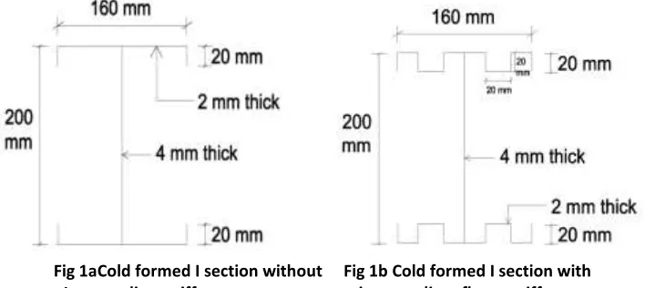
For experimental investigation two different sections are tested, one is cold formed I section without intermediate stiffener and other is cold formed I section with intermediate flange stiffener.
Organized by C.O.E.T, Akola. Available Online at www.ijpret.com
296
Length Depth Width Height of
Leap
Thickness of flange
Thickness of web
1000 mm 200 mm 160 mm 20 mm 2 mm 4 mm
Experimental Investigation
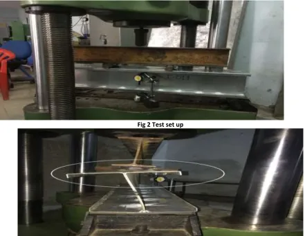
To get the limit state of flexural strength of light gauge steel, four point bending test is used. 1000 kN capacity universal testing machine is used for that purpose. Sections were simply supported at 900mm c/c distance with overall length of section 1000mm. two point loads with the use of spreader beam were applied on the test specimen at distance 300mm apart that is section was equally divide with 300mm distance giving no shear zone in the middle part so as to get pure bending at mid span section. Two dial gauges are used to measure deflection of both top and bottom flange.
Fig 2 Test set up
Organized by C.O.E.T, Akola. Available Online at www.ijpret.com
297
Fig 4 Lateral torsional buckling in web of cold formed I section without intermediate stiffener
Fig 5 Lateral torsional buckling in web of cold formed I section with intermediate flange stiffener
Organized by C.O.E.T, Akola. Available Online at www.ijpret.com
298
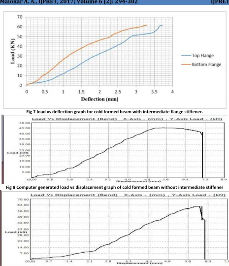
Fig 7 load vs deflection graph for cold formed beam with intermediate flange stiffener.
Fig 8 Computer generated load vs displacement graph of cold formed beam without intermediate stiffener
Organized by C.O.E.T, Akola. Available Online at www.ijpret.com
299
Table 2.1 Experimental Results
Sr. No.
Section Displacement at
Ult. Load
Moment Carrying Capacity
Failure Pattern of Beam
1 Cold formed beam
without intermediate
stiffener
5.1 mm 6.795 kNm This beam showing distortional buckling of
compression flange followed by lateral torsional buckling pattern as shown in fig 3 and 4.
2 Cold formed beam with
intermediate flange
stiffener.
6 mm 9.255 kNm This beam shows lateral torsional buckling
failure pattern. The distortional buckling of compression flange of beam is eliminated due to intermediate flange stiffeners as shown in fig 5.
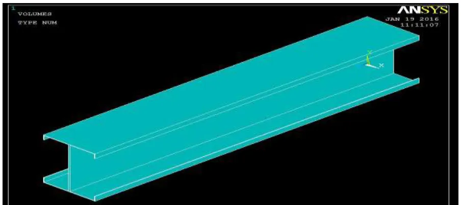
FEM Analysis Using ANSYS
To study flexural behaviour of section under 4-point bending test the finite element analysis based software, ANSYS is used. The modeling of beam is done in CATIA V5R20 software and then it is imported to ANSYS APDL. Precise model is developed by actual boundary condition and load application on 3-D model. Results are obtained for displacement at ultimate load of beam and for ultimate load carrying capacity of beam. To calculate ultimate load carrying capacity of beam Eigen buckling analysis is done in ANSYS APDL.
Organized by C.O.E.T, Akola. Available Online at www.ijpret.com
300
Fig 9Meshing of finite element model in ANSYS
Organized by C.O.E.T, Akola. Available Online at www.ijpret.com
301
Fig 11 Displacement of finite element model in ANSYS
Fig 12Ultimate LCC of finite element model in ANSYS
Table 3.1 Comparison of Experimental and ANSYS Results
Sr. No.
Section Displacement at Ult. Load (mm)
Percentage Error
Moment Carrying Capacity (kNm)
Percentage Error
Exp. ANSYS Exp. ANSYS
1 Cold formed I section
without intermediate stiffener
5.1 4.8 6.25% 6.795 7.326 7.72%
2 Cold formed I section
with intermediate
flange stiffener.
Organized by C.O.E.T, Akola. Available Online at www.ijpret.com
302
The results obtained for displacement at ultimate load and ultimate moment carrying capacity for cold formed light gauge steel I section without and with intermediate flange stiffener from experimental and ANSYS software are in good agreement. From graph of load vs deflection (fig 6) it is concluded that the deflection of top compression flange that is more as compared to bottom tension flange. This indicates that there is distortional buckling of top flange of beam. This type of buckling is generally observed in case of cold formed sections. In case of beams top flanges are susceptible for distortional buckling. From graph of load vs deflection (fig 7) it is concluded that the deflection of top compression flange is closed to bottom flange. This indicates that there is no distortional buckling of top flange of beam. Ultimate moment carrying capacity of cold formed I beam with intermediate flange stiffener experimentally increases by 36.20% as compared to cold formed I beam without intermediate stiffener.
Conclusion
1. Ultimate MCC of cold formed light gauge steel I beam without intermediate stiffener is 6.795 kN-m and it fails
by distortional buckling of compression flange followed by lateral torsional buckling of the web.
2. For cold formed I beam with intermediate stiffener at center of flange ultimate MCC is 9.255 kN-m and it fails
by lateral torsional buckling.
3. Ultimate moment carrying capacity of cold formed I beam with intermediate stiffener at center of flange increases by 36.20% as compared to cold formed I beam without intermediate stiffener.
REFERENCES
1. Borges P., Dinis and Dinar Camotim, Local/distortional mode interaction in cold-formed steel lipped channel beams, Thin-Walled Structures. 2010; 48 :771-785.
2. Haidarali Mohammad Reza, Nethercot David A., Local and distortional buckling of cold-formed steel beams with both edge and intermediate stiffeners in their compression flanges, Thin-Walled Structures 2012; 54:106-112. 3. Luis Laim, Joao Paulo C. Rodrigues and Luis Simoes da Silva, Experimental and numerical analysis on the structural behaviour of cold-formed steel beams, Thin-Walled Structures. 2013; 72 :1-13.
4. Manikandan P., Sukumar S., Naresh L.S., Finite Element Modeling of Cold-formed Beams with Intermediate stiffeners, International Journal of Earth Sciences and Engineering. 2012; 05: 547-553.
5. Sudha K., Sukumar S., Behaviour of Cold Formed Steel Built up I Section under Bending, International Journal of Engineering and Technology. 2013, 05:4622-4631.