Organized by C.O.E.T, Akola & IWWA, Amravati Center. Available Online at www.ijpret.com382
INTERNATIONAL JOURNAL OF PURE AND
APPLIED RESEARCH IN ENGINEERING AND
TECHNOLOGY
A PATH FOR HORIZING YOUR INNOVATIVE WORK
SPECIAL ISSUE FOR
NATIONAL LEVEL CONFERENCE
"SUSTAINABLE TECHNOLOGIES IN
CIVIL ENGINEERING"
COMPARATIVE STUDY OF A PLATE ELEMENT USING FINITE ELEMENT
METHOD AND FINITE STRIP METHOD
APARNA R. NIKUMBH, PROF. ABHINANDAN R. GUPTA
Dept of Civil Engg., College Of Engineering & Technology, Akola
Accepted Date: 13/03/2015; Published Date: 01/04/2015
Abstract: Finite element method is a popular computer aided numerical method based on the discretisation of the domain, structure or continuum into number of elements and obtaining the solution. It converts a infinite number of degree problem to a finite number of degree problem using discretization. On the other hand, finite strip method is of semi-numerical and semi-analytical nature. The finite strip method is applicable to problems which may have complex geometry in their cross-section, but are simple along the length. the application of this method has been extended to thin and thick rectangular and annual sector plates, cylindrical shells, straight and curved box girders and folded plates etc. In this paper, the behaviour of plate subjected to different loading condition with various boundary conditions is studied.
Keywords- Finite element method, finite strip method, boundary conditions, maximum deflection.
.
Corresponding Author: MS. APARNA R. NIKUMBH
Co Author: PROF. ABHINANDAN R. GUPTA
Access Online On:
www.ijpret.com
How to Cite This Article:
Organized by C.O.E.T, Akola & IWWA, Amravati Center. Available Online at www.ijpret.com383
INTRODUCTION
There are four basic types of structures: trusses, cables & arches, framed structures, continuum structures. Continuum structures like membrane plates or shells have much less thickness as compared to its other dimensions. In this paper, the behaviour of plate subjected to different loading condition with various boundary conditions is studied.
There are two methods of analysis.
1. Classical method: It gives us realistic solutions but quite cumbersome and sometimes becomes most impossible for complex structures to analyze for given loading and boundary conditions.
2. Approximate method: Its includes finite difference method, finite element method and finite strip method. all these methods give approximate solutions near to the exact one.
Finite Strip Method
The finite strip method has emerged as a powerful tool of structural analysis. The method is economical and competitive with the well known Finite Element Method. The first paper on this method appeared in 1968 [58]. Since then, the application of this method has been extended to thin and thick rectangular and annual sector plates, cylindrical shells, straight and curved box girders and folded plates etc.
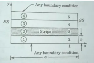
Fig: 1 Rectangular plate descretised into strips
Figure 1 shows a thin rectangular plate. In finite element method, the plate is decretized into elements by drawing lines parallel to x and y directions. But in finite strip method, the rectangular plate is divided into strips by drawing lines parallel to, say, x axis only.
CASE CONSIDERATION AND OBSERVATIONS:
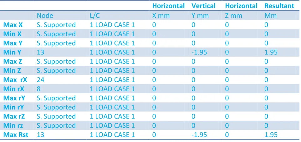
Organized by C.O.E.T, Akola & IWWA, Amravati Center. Available Online at www.ijpret.com384 Consider a plate of 4m x 4m ABCD, simply supported on all sides. Plate is subjected to a uniform pressure of intensity 6 KN/m2, and having thickness 0.12m. Take mesh size h=1m.
Fig. 2
Discretization of plate with 25 nodal points is shown in fig. 2
Fig. 3 Plate ABCD 4mx4m subjected to pressure 6 KN/m2
Since the loading and boundary conditions are symmetric about two axes, only quadrant of the plate is considered for analysis. Also displacement is 0 along the supports.
w1=w2=w3=w4=w5=w10=w15=w20=w25=w24=w23=w22=w21=w16=w11=w6=0
After computational analysis of the same problem we get the following results.
Table no. 1 : Summary of node displacements.
Horizontal Vertical Horizontal Resultant
Node L/C X mm Y mm Z mm Mm
Max X S. Supported 1 LOAD CASE 1 0 0 0 0
Min X S. Supported 1 LOAD CASE 1 0 0 0 0
Max Y S. Supported 1 LOAD CASE 1 0 0 0 0
Min Y 13 1 LOAD CASE 1 0 -1.95 0 1.95
Max Z S. Supported 1 LOAD CASE 1 0 0 0 0
Min Z S. Supported 1 LOAD CASE 1 0 0 0 0
Max rX 24 1 LOAD CASE 1 0 0 0 0
Min rX 8 1 LOAD CASE 1 0 0 0 0
Max rY S. Supported 1 LOAD CASE 1 0 0 0 0
Min rY S. Supported 1 LOAD CASE 1 0 0 0 0
Max rZ S. Supported 1 LOAD CASE 1 0 0 0 0
Min rz S. Supported 1 LOAD CASE 1 0 0 0 0
Organized by C.O.E.T, Akola & IWWA, Amravati Center. Available Online at www.ijpret.com385
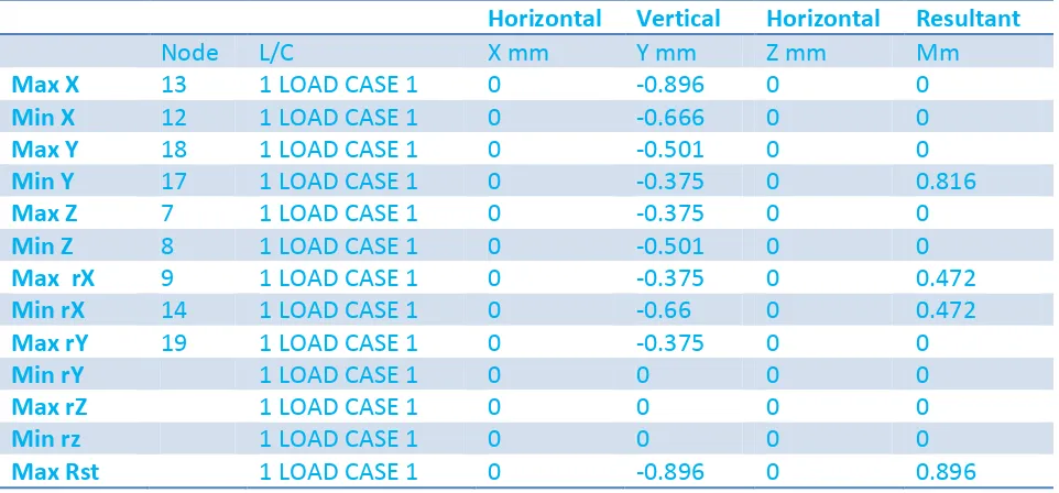
CASE II: Rectangular plates with two opposite edges simply supported and the other two edges clamped
Consider a plate of 4m x 4m ABCD, side AB and CD are clamped while AD and BC are simply supported. plate is subjected to a uniform pressure of intensity 6 KN/m2, and having thickness 0.12m. Take mesh size h=1m.
Fig. 4
Table no. 2: Summary of node displacements
Horizontal Vertical Horizontal Resultant
Node L/C X mm Y mm Z mm Mm
Max X 13 1 LOAD CASE 1 0 -0.896 0 0
Min X 12 1 LOAD CASE 1 0 -0.666 0 0
Max Y 18 1 LOAD CASE 1 0 -0.501 0 0
Min Y 17 1 LOAD CASE 1 0 -0.375 0 0.816
Max Z 7 1 LOAD CASE 1 0 -0.375 0 0
Min Z 8 1 LOAD CASE 1 0 -0.501 0 0
Max rX 9 1 LOAD CASE 1 0 -0.375 0 0.472
Min rX 14 1 LOAD CASE 1 0 -0.66 0 0.472
Max rY 19 1 LOAD CASE 1 0 -0.375 0 0
Min rY 1 LOAD CASE 1 0 0 0 0
Max rZ 1 LOAD CASE 1 0 0 0 0
Min rz 1 LOAD CASE 1 0 0 0 0
Max Rst 1 LOAD CASE 1 0 -0.896 0 0.896
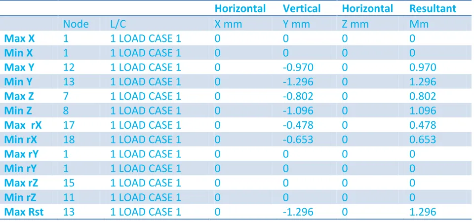
CASE III : Rectangular plate with three edged simply supported and one edge built in.
Organized by C.O.E.T, Akola & IWWA, Amravati Center. Available Online at www.ijpret.com386
Fig. 5
Fig. 6 Rectangular plate with three edges simply supported and one edge built in.
According to given boundary condition and loading condition, nodes having unknown deflection are 7, 8, 12, 13, 17 and 18 only.
Table no. 3 : Summary of nodes displacements.
Horizontal Vertical Horizontal Resultant
Node L/C X mm Y mm Z mm Mm
Max X 1 1 LOAD CASE 1 0 0 0 0
Min X 1 1 LOAD CASE 1 0 0 0 0
Max Y 12 1 LOAD CASE 1 0 -0.970 0 0.970
Min Y 13 1 LOAD CASE 1 0 -1.296 0 1.296
Max Z 7 1 LOAD CASE 1 0 -0.802 0 0.802
Min Z 8 1 LOAD CASE 1 0 -1.096 0 1.096
Max rX 17 1 LOAD CASE 1 0 -0.478 0 0.478
Min rX 18 1 LOAD CASE 1 0 -0.653 0 0.653
Max rY 1 1 LOAD CASE 1 0 0 0 0
Min rY 1 1 LOAD CASE 1 0 0 0 0
Max rZ 15 1 LOAD CASE 1 0 0 0 0
Min rZ 11 1 LOAD CASE 1 0 0 0 0
Max Rst 13 1 LOAD CASE 1 0 -1.296 0 1.296
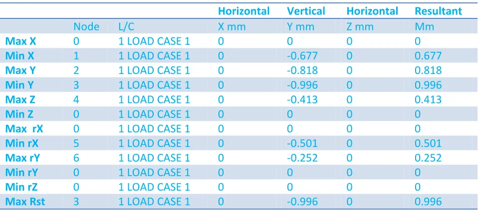
CASE IV : Rectangular plate with one or two adjacent edges simply supported and other edges built in.
Organized by C.O.E.T, Akola & IWWA, Amravati Center. Available Online at www.ijpret.com387
Fig. 7
Fig. 8 Rectangular plate with one or two adjacent edge simply supported and other edges built in.
Table 4: Summary of node displacements.
Horizontal Vertical Horizontal Resultant
Node L/C X mm Y mm Z mm Mm
Max X 0 1 LOAD CASE 1 0 0 0 0
Min X 1 1 LOAD CASE 1 0 -0.677 0 0.677
Max Y 2 1 LOAD CASE 1 0 -0.818 0 0.818
Min Y 3 1 LOAD CASE 1 0 -0.996 0 0.996
Max Z 4 1 LOAD CASE 1 0 -0.413 0 0.413
Min Z 0 1 LOAD CASE 1 0 0 0 0
Max rX 0 1 LOAD CASE 1 0 0 0 0
Min rX 5 1 LOAD CASE 1 0 -0.501 0 0.501
Max rY 6 1 LOAD CASE 1 0 -0.252 0 0.252
Min rY 0 1 LOAD CASE 1 0 0 0 0
Min rZ 0 1 LOAD CASE 1 0 0 0 0
Max Rst 3 1 LOAD CASE 1 0 -0.996 0 0.996
Finite Strip Method
Thin Rectangular plate – Lower order strip
Formulation
Organized by C.O.E.T, Akola & IWWA, Amravati Center. Available Online at www.ijpret.com388 And
In which I indicates harmonic number and r indicates total harmonics to be used. The displacement variation over strip region is expressed as
These are Hermitian shape functions. The trigonometric function (sine function) satisfies boundary cndition at x=0 and x=a, namely
Organized by C.O.E.T, Akola & IWWA, Amravati Center. Available Online at www.ijpret.com389 number of times. This is known as decoupling of equations. This is a great advantage resulting in computational economy. The half band width is fixed at 4.The bending curvatures are realated to displacement derivatives as
The stress resultants
Are related to bending curvatures through elasticity matrix as
In which
The strain energy in the strip is
Substituting from equations
Hence the element stiffness matrix is written as
Organized by C.O.E.T, Akola & IWWA, Amravati Center. Available Online at www.ijpret.com390 After carrying out explicit multiplications, it is seen that each term of ] contains one of the following two terms:
Hence the stiffness matrix of the strip takes the decoupled diagonal form as
Organized by C.O.E.T, Akola & IWWA, Amravati Center. Available Online at www.ijpret.com391 In general case of end suppport conditions, the displacement function of a plate strip may take the following form:
W(x,y) =
Where [N] is the matrix of shape functions of x, and Ym (y) is the m-th term of a series of functions of y.
The most commonly used is the series of beam eigen functions which are derived from the solution of the beam vibration differential equation
The general form of the beam eigen functions is
Y(y) = c1 sin (µy) + c2 cos (µy) + c3 sinh (µy) + c4 cosh (µy)
With the coefficients ci to be determined by the end conditions. These have been worked out
explicitly for the various end conditionns and are listed below:
(a) Both ends simply supported, i.e., Y(0) = (0) = 0 and Y(l) = (l) = 0:
Ym (y) = sin (µm y),
Where, µm =
(b) Both ends clamped, i.e. Y(0) = (0) = 0 and Y(l) = (l) = 0:
Ym (y) = sin (µm y) - sinh (µm y) – αm [cos (µm y) -cosh (µm y)]
Organized by C.O.E.T, Akola & IWWA, Amravati Center. Available Online at www.ijpret.com392 Solutions for same plates problems by Finite Strip Method (FSM) and also by Finite Element Method (FEM).
Sr. No.
Plates with various boundary conditions and various loading conditions
Material properties
Maximum resultant deflection by FSM(in mm)
Maximum resultant
deflection by FEM (in mm) 1. Plate 4m x4m and 12cm thick
simply supported on all side (SSSS)
E = 21.7185
KN/m2 and = 0.17.
1.92 1.95
2. Plate 4m x4m and 12cm with two opposite edges simply supported and the other two edges clamped
E = 21.7185
KN/m2 and = 0.17.
0.866 0.896
3. Plate 4m x4m and 12cm with three edged simply supported and one edge built in.
E = 21.7185
KN/m2 and = 0.17.
1.121 1.296
4. Plate 4m x4m and 12cm with one or two adjacent edges simply supported and other edges built in.
E = 21.7185
KN/m2 and = 0.17.
0.912 0.996
CONCLUSION
Thus, for making structure safe and durable , it is utmost important to analyse the structure for various possible practical conditions and design on the base of it. Some important parameters that should be considered are bending moment, shear force, deflection etc. and the factors responsible for making difference are geometry, dimensions, material used and boundary conditions. One such factors influence is suited in this report and behavior of plat or slab is studied for various boundary condition subjection. Thus, this study helps to analyse and review effect of support or boundary conditions on stability of structure and probable design consideration.
REFERENCES
Organized by C.O.E.T, Akola & IWWA, Amravati Center. Available Online at www.ijpret.com393 2. Ray W. Clough, James L. Tocher, Finite Element Stiffness matrices for analysis of plate bending.
3. B. Sidda Reddy, A. Ramanjaneya Reddy, J. Suresh Reddy and Vijaya Kumar Reddy.
4. S. N. Tande, Higher order finite strip analysis of clamped reinforced concrete skew slabs, 31st Conference on Our World In Concrete & Structures, 2006.
5. Zhanjie Li, Buckling analysis of the finite strip method and theoretical extension of the constrained finite strip method for general boundary conditions, 2009.
6. Wong Wing-Tai, Finite Strip method of structural analysis, Hong Kong, 1983.