185 Copyright © 2011-15. Vandana Publications. All Rights Reserved.
Volume-5, Issue-1, February-2015
International Journal of Engineering and Management Research
Page Number: 185-190
An Embedded based Robotic Arm to Find Unauthenticated Code
Saranya.B1, Sasikala.N2, Sharmila.K3, Nandini.S4 1,2,34
Departmat of Electricals and Electronics Engineering, INDIA
ABSTRACT
Robotics is the science of designing and building robots suitable for real-life applications in automated manufacturing and other non-manufacturing environments. This project is based on robotics based on the arm movements where less weighted objects are lifted. The main objective of this project is to find the other objects except the particular code present in the objects, it automatically finds an object that we to have remove. In offices, schools, colleges or in super markets it takes plenty of time to find a particular person’s record or to separate a particular item. This difficulty can be overcome by using robot’s arm movement with the scanner in order to reduce man power and time. Bar code scanner is used to read the particular code of an object and sends the information to the microcontroller kit. This kit compares the code with the predefined code if the code matches it is a good product and process is stopped immediately, if the code does not matches, then it is a bad product so the arm picks that object and keeps it separately.
Keywords : Robotics, bar code scanner, DC motor, Micro controller, LCD display.
I.
INTRODUCTION
The arm control in robots is very popular in the world of robotics.A robotic arm is usually programmable with functions similar to a human arm. Robotic arm can be used to perform a variety of tasks with great accuracy. The use of robots has been increasing in this world. It is more helpful for the people in many ways by reducing the time and makes the work easier.Robots are capable of amazing feats of strength and speed. This project is also based on robotics which is used to find the bad product using a barcode scanner. Robots are meant to relieve people, making a task easier or aiding a person who wants or needs assist. The main use of robots has so far been in the automation of mass manufacture industries, where the same, definable tasks must be performed repeatedly in exactly the same fashion. This project aims to create a straightforward and repeatable process to minimize the human work to a greater extent.The ports of the microcontroller are used to control the operation of the DC motor, scanner, electromagnets and servo motor. The program is done using
keil C.
This project aims to find a good product using the basic arm movements of the robot so as to reduce the man power and the working time. Limiting sensors is used in the sides, top and bottom of the arm so that it automatically goes downward from upward direction, leftward from rightward direction and vice versa. Meanwhile the scanner scans the code present in that particular object. A low cost embedded based code finder using robotic arm movement, which consists of servo motor, stepper motor, electromagnet, bar code scanner and microcontroller. Comparing with digitize delicate texts in a book using robotic arm movement with a scanner, this system needs only one stepper motor, one servo motor and two fingered arm[5]. The digitize delicate texts in a book using robotic arm movement with a scanner used 3 stepper motor and monitor arrangement. It is more expensive.[2] 3 fingered arm for robots which can be used for small applications in medical field like laproscopic surgery. To hold or handle light materials 3 fingers are enough for robots.[1] The electromagnets are used to hold micro objects using robotic arm. So we can use the electromagnet to hold thin papers. The code prompting the control of servo motor, stepper motor and electromagnet interfaced with 8051 has been implemented using embedded C [19] in case of reliability and portability instead of relying on assembly language programming.
II.
PROPOSED SYSTEM
186 Copyright © 2011-15. Vandana Publications. All Rights Reserved.
III.
ATMEL 89C51
The Atmel 89C51 is a less-power, more-performance CMOS 8-bit microcomputer with 4K bytes of Flash programmable and erasable read only memory (PEROM). The Atmel 89C51 device is manufactured using Atmel’s high-density nonvolatile memory technology. Atmel AT89C51 is a powerful microcomputer which provides a highly-flexible and cost-effective solution to many embedded control applications.
IV.
RELAY
A relay is an electrically operated relays use an mechanism mechanically, other than extra operating principles are also used. Relays are used where it is essential to control a circuit by a low-power signal, or where more than a few circuits must be controlled by one signal. The first relays were used in extensive distance telegraph circuits, repeating the indicator coming in from one circuit and re-transmitting it to one more. Relays were used extensively in telephone exchanges and early computers to perform logical operations.
V.
DC SERVO MOTOR WORKING
A servo motor consists of numerous main parts, the motor and gearbox, a position sensor, an inaccuracy amplifier and motor driver and a circuit to decode the requested position. Figure 1 contains a block diagram of a distinctive servo motor unit. The radio control receiver system (or other controller) generates a pulse of varying length approximately every 20 milliseconds. The pulse is normally flanked by 1 and 2 milliseconds long. The extent of the pulse is used by the servo to determine the position it should rotate to.
Figure 1 : Block Diagram of Servo Motor
VI.
PULSE WIDTH TO VOLTAGE
CONVERTER
The control pulse is feed to a pulse width to voltage converter. This circuit charges a capacitor at a steady rate while the pulse is high. While the pulse goes low the charge on the capacitor is fed to the output via a suitable defense amplifier. This fundamentally produces a voltage related to the length of the applied pulse. The circuit is tuned to fabricate a useful voltage over a 1ms to 2ms period. The output voltage is buffered and consequently does not decay significantly between control pulses so the length of time between pulses is not critical.
VII.
POSITION SENSOR
The current rotational position of the servo motor output shaft is read by a sensor. This is normally a potentiometer which produces a voltage that is related to the absolute angle of the output duct. The position sensor then feeds its current value into the Error Amplifier which compares the current position with the commanded position from the pulse width to voltage converter.
VIII.
ERROR AMPLIFIER
The error amplifier is an operational amplifier with negative feedback. It will always attempt to minimize the difference between the inverting (negative) and non-inverting (positive) inputs by driving its output is the correct direction. The production of the error amplifier is either a negative or positive voltage representing the difference between its inputs. The greater the difference the greater will be the voltage. The error amplifier output is used to drive the motor. If it is optimistic the motor will turn in one direction, if pessimistic the other. This allows the error amplifier to reduce the difference between its inputs and so make the servo go to the commanded position. The servo usually contains a single integrated circuit and a hand full of discreet components to implement the entire control system.
IX.
TIMERS
187 Copyright © 2011-15. Vandana Publications. All Rights Reserved.
X.
LIMIT SWITCH
Limit switch is a switch operated by the motion of a machine part or presence of an entity. They are used for control of a machine, as safety objects transitory a point. Standardized bound switches are industrial organize components manufactured with a diversity of operator types, including lever, roller plunger, and whisker type. Bound switches may be directly mechanically operated by the movement of the operating lever. A magnet mounted on some moving part. field, by capacitance, or by sensing a magnetic field.
XI.
DRIVER CIRCUIT
A driver is an component, such as a high-power usually used to normalize current flowing through a circuit or is used to control the other factors such as other components, a few devices in the circuit. The term is often used, for illustration, for a specialize
mode An
measured a driver for within a broad range of in driver stages of a circuit require different characteristics to other circuit stages. For instance in a transistor power amplifier, naturally the driver circuit requires current gain, often the aptitude to discharge the following transistor bases speedily, and low output impedance to avoid or minimize distortion.
XII.
BARCODE SCANNER
A barcode reader or barcode scanner is an electronic device for reading printed barcodes. Similar to a flatbed scanner it consists of a light resource, a lens and a light sensor translating optical impulses into electrical ones. In addition, almost all barcode readers contain decoder circuitry analyzing the barcode's image data provided by the sensor and sending the barcode's content to the scanner's output port.
XIII.
BLOCK DIAGRAM
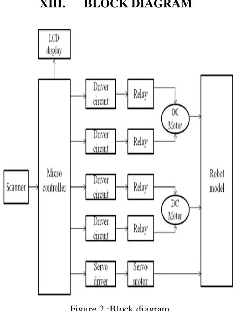
Figure 2 :Block diagram
The barcode scanner is used to read the barcode present on the object. The microcontroller will check the input from the barcode scanner with the predefined code present in it. If the barcode is not matched with the code then the microcontroller will send the signal to the driver circuits for controlling the motor operations. Two driver circuits are used to control the forward and backward motions of DC motors. One driver circuit is used to control the servo motor. The microcontroller will control the operations of the motors with respect to the predefined timing and limiting sensor’s output. The servo motor is used to control the operation of the electromagnet which is used to pick and hold the object. One DC motor is used to move the arm in upward and downward directions. Another DC motor is used to rotate the arm in left and right directions.
XIV.
HARDWARE MODULE
188 Copyright © 2011-15. Vandana Publications. All Rights Reserved.
When relay 1 is in the ON state in addition
to relay 2 is in the OFF state, the motor is running in the frontward direction.
When relay 2 is in the ON state in addition
to relay 1 is in the OFF state, the motor is running in the overturn direction.
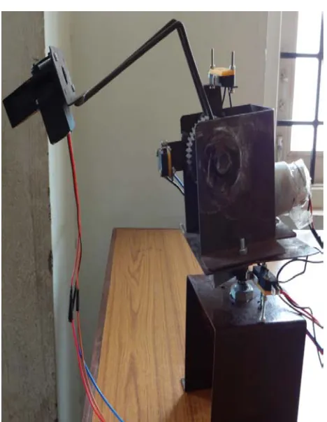
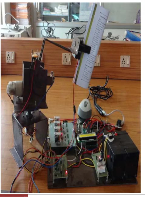
Figure 3:. Hardware module
1. Bar code scanner- Scans the bar code present in an object.
2. DC driver circuit- Makes forward and backward motions of DC motor.
3. Servo driver circuit- Controls the electromagnet. 4. Voltage regulator- Used to convert 12V to 5V. 5. Battery- Supplies power to all the circuits. 6. LCD display- Displays the current operation.
7. IC base with 89C51- Used to hold the Atmel 89C51IC.
XV.
RESULTS
Case : I - YES CONDITION
Figure 4 : Good Product Display
Figure 5 : Picking Good Product
If the code is matched with the predefined code then it will be displayed as “good product” in the LCD display. Then the robot’s arm remains in the same position.
Case : II - NO CONDITION
189 Copyright © 2011-15. Vandana Publications. All Rights Reserved.
unmatched code and makes an upward movement.
Figure 6: Bad Product Display
Robot’s arm with the picked object moves to the other side so as to place the unauthenticated object away from the authenticated one. Then the robot’s arm makes a downward movement to place the object over the other side.
Figure 7: Scanning The Product
Figure 8 : Arm Movement
XVI.
CONCLUSION AND FUTURE
ENHANCEMENT
This project represents the design and implementation of a robotic arm by using two DC motors and a servo motor with a barcode scanner to find a code. The arm is designed to make an upward and downward movement up to 90 degree. The arm movement is limited by the limiting sensors. The 90 degree and the left and right movement is made possible by means of a DC motor. The servo motor is used to control the electromagnet. The program is developed using the KEIL C software.
The relay switches, driver circuits controls the DC and the servo motors. A bar code scanner is fixed to scan the code present on an object. This can also be used in super markets to pick a selected item or to remove an item from the list of items.
190 Copyright © 2011-15. Vandana Publications. All Rights Reserved.
REFERENCES
[1] Calgar Elbuken, Mir Behrad Khamesee, and Mustafa Yavuz, ‘Design and Implementation of a micromanipulation System using a Magnetically Levitated MEMS Robot,’ IEEE/asme transactions on mechatronics, Vol. 14, pp. 4, August 2009
[2] Ritsuya Oshima, Toshio Takayama, Toru Omata,
Kazuyuki Kojima, Kozo Takase, and Naofumi Tanaka, ‘Assemblable Three-Fingered Nine-Degrees-of-Freedom Hand for Laparoscopic Surgery’, IEEE/asme transactions on mechatronics, vol. 15, no. 6, december 2010
[3] Kurt E. Clothier and Ying Shang, ‘A Geometric
Approach for Robotic arm kinematics with Hardware Design, Electrical Design, and Implementation’ Hindawi Publishing Corporation, Journal of Robotics, Volume 2010, Article ID 984823, 10 pages, doi:10.1155/2010/984823
[4] Yong Zhang, Brandon K. Chen, Xinyu Liu, and Yu
Sun, ‘Autonomous Robotic Pick-and-Place of
Microobjects’, IEEE transactions on robotics, vol. 26, no. 1, february 2010
[5] Michael Dumiak,”Book Scanning Robots for Degitize Delicate Texts” IEEE Spectrum,vol 1,January 2008 in www.spectrum.ieee .org
[6] N. Zemiti, G. Morel, T. Ortmaier, and N. Bonnet, “Mechatronic design of A new robot for force control in
minimally invasive surgery,” IEEE/ASME Trans.
Mechatronics, vol. 12, no. 2, pp. 143–153, Apr. 2007. [7] S. Fatikow, T. Wich, H. Hulsen, T. Sievers, and M. Jahnisch, “Microrobot System for automatic nanohandling inside a scanning electron microscope,”IEEE/ASME Trans.Mechatronics, vol. 12, no. 3, pp. 244–252, Jun. 2007.
[8] W. Ding, H. Zhang, and C. Cetinkaya, “Rolling resistance moment-based Adhesion characterization of microspheres,” J. Adhes., vol. 84, no. 12,Pp. 996–1006, 2008.
[9] W. H. Wang, X. Y. Liu, and Y. Sun, “Contact detection in microrobotic Manipulation,” Int. J. Robot. Res., vol. 26, pp. 821–828, 2007.
[10] R. H. Taylor and D. Stoianovic, “Medical robotics in computer-integrated Surgery,” IEEE Trans. Robot. Autom., vol. 19, no. 5, pp. 765–781, Oct.2003, 2010. [11] I. W. Park, B. J. Lee, S. H. Cho, Y. D. Hong, and J. H. Kim, “Laser-based kinematic calibration of robot manipulator using differential kinematics,” IEEE/ASME Transactions on Mechatronics, pp. 1–9, 2011.