Volume 3, Issue 3, March 2014
Page 334
Abstract
Inexpensive wireless communication, computation and sensing is now need of the Wireless Sensor Network (WSN). Wireless sensor networks (WSNs) comprises large number of wireless sensor nodes which can sense and process data in the environment in a periodic manner. In WSN, as the sensor node depends on its internal battery power, energy efficiency and lifetime of sensors have become a key issue on the performance of wireless network. To make effective utilization of energy resources of a sensor node, communication protocols can be designed precisely. Clustering the sensor nodes is one of the effective techniques to achieve this goal.
Low- Energy Adaptive Clustering Hierarchy (LEACH) - A cluster based routing algorithm was proposed as a solution for low power consumption. One of problems in the LEACH protocol is “Extra Transmissions”. The goal of our research is to optimize the energy consumption of wireless sensor network by introducing a novel and adaptive technique on the traditional clustering protocol of the wireless sensor network. In order to improve network performance, the Distance based LEACH algorithm is proposed where the improvement is done in cluster formation technique based on distance parameter. In cluster formation phase of modified LEACH distance of sensor node from cluster head plus distance of cluster head to base station is taken into account.
Keywords: Wireless Sensor Network, LEACH protocol, Lifetime of WSN, Cluster
1.
I
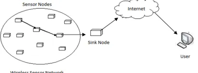
NTRODUCTIONAdvances in wireless communication made it possible to develop wireless sensor networks (WSN). Now a day’s wireless sensor networks (WSNs) have been identified as one of the emerging technologies. A WSN consist of spatially distributed autonomous sensor nodes to cooperatively monitor physical or environmental conditions. The nodes communicate in wireless fashion. Source nodes transmit their data to destination node either directly or through intermediate nodes. These destination nodes are connected to a central gateway, also known as base station or sink. Central gateway provides connection to wired world where data can be collected, processed and analyzed. Figure 1 shows the general architecture of wireless Sensor network.
Figure 1. General architecture of wireless Sensor network.
These sensor nodes are used for event detection and continuous sensing which consist of processing unit (for data processing), Sensing unit, battery (for energy) and transceiver (for receiving and sending signals or data from one node to another). The size of each sensor node varies with applications. For example, in some military or surveillance applications it might be microscopically small. Its cost depends on its parameters like memory size, processing speed and battery [8].
As these sensor nodes are of low cost, a network of hundreds or thousands of nodes are also possible which helps to enhance the coverage area as well as reliability of network. These sensors have data processing and communication capabilities [5]. They sense the conditions in which they are surrounded and transform their data to electronic signals. The electronic signals are transmitted over radio waves to the base station (BS).
It is inefficient for all the sensors to send their data directly to the BS as sensor nodes are energy constrained. Since data generated from neighboring sensors is redundant, the amount of data generated in large networks is usually enormous for the BS to process. To solve these problems, we can perform data aggregation in sensor nodes .Data aggregation involves the fusion of data from multiple sensor nodes at intermediate nodes and transmission of aggregated data to the BS or Sink. Data aggregation can eliminate redundancy; minimize the number of transmissions and thus save energy [2]-[7].
Distance Based Cluster Formation Technique
for LEACH Protocol in Wireless Sensor
Network
Snehal Kole1, Mr.K.N.Vhatkar2, Mr.V.V.Bag3
1,2&3
Volume 3, Issue 3, March 2014
Page 335
The use of wireless sensor networks is increasing day by day and at the same time it faces the problem of energy constraints in terms of limited battery lifetime. As each node depends on energy for its activities, it is necessary to improve network lifetime of wireless sensor networks by effectively reducing energy consumption. To achieve this objective many routing algorithms have been proposed. Among all the proposed methods, hierarchical routing protocols greatly satisfy the limitations and constraints in WSNs [4]. It is mainly considered as a two layer architecture where one layer is engaged in cluster head selection and the other layer is responsible for routing. A cluster head (CH) in hierarchical routing is the node which is responsible for collecting data from other nodes in the cluster, aggregating all data and sending the aggregated data to the base station.2.
R
ELATED WORKHeinzelman et al. [9] proposed the cluster-based routing protocol called LEACH (Low-Energy Adaptive Clustering Hierarchy).It assumes that all the sensor nodes can communicate with the base station directly. In order to save energy, LEACH only chooses a fraction of p of all sensor nodes to serve as cluster heads. The rest of the sensor nodes join the proper clusters according to signal strength from cluster heads. The limitation of LEACH is that it offers no guarantee about the placement or number of cluster heads. Therefore, for better performance an enhancement over the LEACH protocol was proposed called LEACH-C which uses a centralized clustering algorithm [9]. LEACH-C protocol can produce better performance by dispersing the cluster heads throughout the network.
Manjula et al. [6] proposed LEACH-CE protocol where 5% of alive nodes in the network are cluster heads. The base station makes 10% of the nodes in the network to go to sleep mode. This is done before the selection of cluster heads. The nodes in sleep mode do not sense any data nor do they receive any information from base station. Base station controls the operation of all nodes. This mode chooses randomly the nodes switched to sleeping mode which does not guarantee the quality of data even if it preserves the lifetime. To extend network lifetime, Vice-LEACH protocol was proposed in which vice cluster head is selected that will work only when the current cluster head die. The proposed approach improves the network life as the cluster head never die [1].
2.1 LEACH
Low-Energy Adaptive Clustering Hierarchy (LEACH) is one of the most popular hierarchical routing protocols. The operation of LEACH is divided into rounds. Each round starts with a set-up phase, followed by a steady-state phase. During the set-up phase, each sensor node tries to select itself as a cluster head according to probability model. For selecting a cluster head, each sensor node generates a random number in between 0 and 1. If the number is less than the threshold T (n), the sensor node selects itself as a cluster head for current round.
The threshold T (n) is presented as follows:
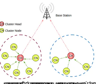
Where, P equals the suggested percentage of cluster-heads, r is the current round and G is the set of nodes that have not been cluster head in the last 1/p rounds. Node which has been selected as cluster head will broadcast a message using CSMA MAC protocol and non cluster head nodes will choose nearest cluster head to join that cluster. Figure 2 shows the clustering architecture of LEACH protocol.
Figure 2 Cluster formations in LEACH
Volume 3, Issue 3, March 2014
Page 336
3.
D
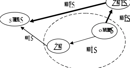
ISTANCE BASED LEACH ALGORITHMDuring cluster formation of LEACH algorithm, some nodes have to select cluster heads that have longer distance to BS as compare to them. In this case, data is sending to cluster head in backward direction and then that data has to travel a longer distance to reach to BS. These transmissions are called extra transmissions and it affects on network’s lifetime by wasting node’s energy. As demonstrated in figure 3.
Figure 3 Extra Transmissions
In figure, there exist two paths from Node to sink i.e. Path1 = (Node-CH1, CH1-Sink) and Path2=(Node-CH2,CH2-Sink).
Here, length of Path1 is greater than length of Path2 i.e. (D1+D2) > (D3+D4) where D1<D3. According to LEACH, node joins the closest cluster head CH1 even though resultant distance (D1+D2) > (D3+D4).
To extend network lifetime and to solve this extra transmission problem, the proposed algorithm considers distance of node from the first cluster head plus distance of cluster head from sink vs. distance of node from the second cluster head plus distance of that cluster head from sink while cluster formation. By considering same example, if a Node joins cluster-head CH2 instead of cluster-cluster-head CH1 even though CH1 is closer to Node then extra transmission can be minimized, as (D3+D4) < (D1+D2), as shown in figure 4,
Figure 4. An example showing how extra transmission can be minimized. The following pseudo code describes the functionality of Distance based LEACH protocol:
Pseudo code: Notations:
S: Set of nodes in network CH: Cluster Head
K: Number of Cluster heads SCH : Set of Cluster Heads
SNCH : Set of non Cluster Heads
Algorithm:
For every node n in S do {
r random (0,1)
if ( Einit (n) > 0 & r mod (1/popt ) ≠ 0) then
Compute T(n)
if ( r < T(n) & K < no. of CH) then CCH {n} = TRUE
else
CCH {n} = FALSE
D3 Sink
CH2
CH1
Node D1 D2
D4
D3 Sink
CH
CH1
Node D1 D2
Volume 3, Issue 3, March 2014
Page 337
end ifend if
if (CH {n} = TRUE) then send ADVi to all ni ϵ S
for every CH in SCH
if { dist(n,CHi)+ dist(CHi,BS) < min_dist}
set min_dist = dist(n,CHi)+ dist(CHi,BS)
send join(IDi) to all ni ϵ SNCH
CH sends TDMA slots to SNCH in Cluster (C)
SNCH send data to SCH
SCH aggregate data & send it to BS
}
4.
E
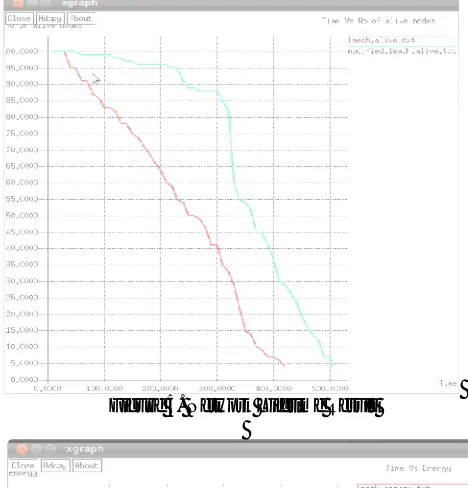
XPERIMENTAL RESULTSFor evaluating the performance of proposed algorithm, we compare it with LEACH protocol by performing simulation of both algorithms in NS2. Our network consists of 100 wireless sensor nodes where each node is distributed randomly in the area of 100*100m. The Base Station position i.e. X and Y co-ordinate of BS is (25,120). All nodes start with the initial energy of 2 Joules. Size of each data packet is 500 bytes.
Figure 5. Network Lifetime Result
Volume 3, Issue 3, March 2014
Page 338
Figure 5 and 6 illustrates the performance of improved LEACH compare to LEACH algorithm in terms of network lifetime and energy consumption. In above figure 5, LEACH protocol works upto 420 seconds while modified distance based LEACH works upto 505 seconds. Figure 6 shows that modified LEACH works better with less energy consumption than LEACH. Hence, It is clear from the figure that wireless sensor network performs longer with modified LEACH algorithm expending minimum energy as compare to LEACH.5.
C
ONCLUSIONIn this paper, we have studied well known energy efficient LEACH protocol and proposed an improvement over it to enhance network lifetime. The distance of the node from base station is considered as an important factor in cluster formation which will reduce some extra transmissions in existing LEACH protocol. Analysis of simulation result proves the improvement in the performance of original LEACH algorithm.
References
[1] Ahlawat A, Malik V, “An Extended Vice-Cluster Selection Approach to Improve V Leach Protocol in WSN,” Third International Conference on Advanced Computing and Communication Technologies (ACCT), pp. 236-2240 © 2013 IEEE.
[2] B. Krishnamachari, D. Estrin, and S. Wicker, “The Impact of Data Aggregation in Wireless Sensor Networks,” 22nd
InternationalConference on Distributed Computing Systems Workshops, pp. 575-578, 2002.
[3] Heinzelman WB, “Application-specific protocol architecture for wireless networks.” PhD thesis. Massachusetts Institute of Technology, June 2000.
[4] J. N. Al-Karaki and A. E. Kamal. “Routing techniques in wireless sensor networks: a survey," Wireless Communications, IEEE, vol.11, no.6, pp. 6- 28, 2004.
[5] M. Ilyas and I. Mahgoub, “Handbook of Sensor Networks: Compact Wireless and Wired Sensing Systems,” International Journal of Distributed Sensor Networks, vol. 4, no. 4, pp. 369-369, 2008.
[6] Manjula SH, Reddy EB, Shaila K, Nalini L, Venugopal KR, Patnaik LM. “Base-station controlled clustering scheme in wireless sensor networks,” Wireless days, p. 1-5. 1st IFIP. November 2008.
[7] R. Rajagopalan, and P. Varshney, “Data Aggregation Techniques in Sensor Networks: A Survey,” IEEE
Communications Surveys &Tutorials, vol. 8, no. 4, pp. 48-63, 2006.
[8] Romer, Kay; Friedemann Mattern "The Design Space of Wireless Sensor Networks,” IEEE Wireless Communications, Dec. 2004.