TEXT DEPENDENT SPEAKER RECOGNITION ON
DIGITAL SIGNAL PROCESSOR: IMPLEMENTATION
AND OPTIMIZATION
1
Sheeba Kumari M, 2Thanuja I K
1Dept. Of ECE, New Horizon College of Engineering,
Bengaluru, India.
2Dept. Of ECE, New Horizon College of Engineering,
Bengaluru, India.
ABSTRACT
Speaker recognition is the process of automatically recognizing the speaker, based on individual information included in speech signals. The speaker is identified by investigating the extracted features of the unknown speech and then comparing it with the stored extracted features in the database. This paper describes the implementation of text dependent Speaker Recognition System on TMS320C6713 DSK using Code Composer Studio v3.1 as the Integrated Development Environment (IDE). Feature extraction is done using Mel Frequency Cepstral Coefficients and the compressed speech signal is stored in a speaker database. A distortion measure based on minimization of Euclidean distance is used to match an unknown speaker’s voice with the database. Digital Signal Processors being the fastest method for implementing signal processing solutions offers an excellent platform for developing the specified system. Finally, we provide the software and hardware optimization techniques for reducing the number of clock cycles aiding the development of a faster system.
Keywords: speaker recognition; MFCC; data compression; TMS320C6713 DSK; optimization techniques.
I. INTRODUCTION
Speech is always regarded as a powerful identity of a person, owing to its rich dimensions such as speech text (words), gender, attitude, emotion, health situation, pitch etc. Speech processing is a special case of digital signal processing, where the desired information is extracted from a speech signal.
method, no assumption about the text being spoken is made, but the system must model the general underlying properties of speaker’s vocal spectrum. In general, text dependent systems are more reliable and accurate, since both the content and voice are compared in similar phonetic environments [12].
The speaker recognition system is implemented in two stages, namely, training stage and testing stage. Training stage involves building a model of the voice of each target speaker as well as a model of a collection of background speakers using speaker-dependent features extracted from the speech waveform [2]. The data used in building a speaker model is called the training data. During the testing or recognition stage, the features measured from the test data of a speaker using the same process is matched against speaker models obtained during training.
In this paper, we present the implementation of a text dependent DSP based embedded system for speaker recognition in which a text (password) uttered by the person is used to model the speaker. Through our experiments we also analyzed the reduction in the execution time.The paper is organized as follows. In Section II we provide a brief description of speaker recognition system. The implementation steps on TMS320C6713 DSK board, which includes the various stages of the algorithm, are presented in Section III. Section IV provides an overview on the software and hardware framework. The hardware and software optimization possibilities are discussed in Section V. Finally the simulation results are presented in Section VI and we summarize the conclusions in Section VII.
II.
SPEAKER RECOGNITION SYSTEM
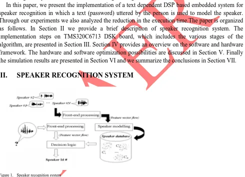
Figure 1. Speaker recognition system
The main blocks of a speaker recognition system are:
III. IMPLEMENTATION ON DSP PROCESSOR
The implementation of speaker recognition process consists of two phases. 1) Training phase.
2) Testing (pattern matching) phase.
In the training phase, reference models are generated from the reference speech signals by obtaining the statistical parameters from the reference speech signal through feature extraction. A test signal is then compared with the reference templates at the pattern matching stage. The comparison is based on distance measurement [2]. After comparison, the test pattern is labeled to a speaker model at the decision stage based on the minimum risk criterion. We developed the system using Texas Instruments’ TMS320C6713 DSK with the speaker recognition algorithm implemented on it. The DSP is encoded with the user’s voice signature. Every time user recognition is initiated, the algorithm compares the speaker’s voice with the signature already stored in the database.
The integral processes involved in the algorithm are: • Pre-processing
• Feature Extraction
• Pattern Matching
A. Pre Processing Module
In this module the main functions performed are:
• Sampling: This is done to obtain discrete samples from analog signal.
• Frame Blocking & Windowing: When the speech signals are examined over short periods of
time (5 to 50 ms), the signals are reasonably stationary. So the signal is blocked into frames of 20-30 ms. To avoid the loss of any information due to windowing, adjacent frames are overlapped. After framing, each frame is multiplied with a hamming window.
B. Feature Extraction
The speech feature extraction is all about reducing the dimensionality of the input voice, while maintaining the discriminating power of the signal. The number of training and test vectors needed for the classification problem grows exponentially with the dimension of the given input, so we need feature extraction. Mel Frequency Cepstral Coefficients (MFCC) technique [1], [2] is to extract features from the speech signal. The MFCC algorithm is based on mel scale, which is linear for frequencies less than 1 kHz and logarithmic thereafter.
The different processes to obtain MFCC from the windowed pre-emphasized digital speech frames are:
• FFT: On each frame, we apply FFT to obtain the frequency domain representation of the signal. The resultant will be a complex signal. The power of the signal in frequency domain is calculated by summing the square of real and imaginary part of the signal in frequency domain. The power signal will be a real one.
• Mel frequency warping: On each frame, the Mel filter bank is to be applied. The resultant is
frequency is given by:
Mel( f ) = 1125 * log(1 + f/700 ) in mels
Mel for 4000 Hz is computed and is divided by 20. The frequency edge of each filter is computed by substituting the corresponding mel. Having found the edge frequencies and center frequencies of the filter, boundary points are computed to determine the transfer function of the filter. Boundary points are given by:
f(m) = {N*Mel-1(Mel(fl) + m/t [ Mel(fh) - Mel(fl)])} /fs
where fs is the sampling frequency, fh is the upper cut-off frequency, fl is the lower cut-off frequency, N is the total number of samples, m is the number denoting the filter, t is the total number of filters + 1. The transfer function of the filters is computed using the formula:
H_m(k) = 0 ; if k < f(m-1)
= (k-f(m-1))/(f(m)-f(m-1)) ; if f(m-1) ≤ k ≤ f(m)
= (f(m+1)-k)/(f(m+1)-f(m)) ; if f(m) ≤ k ≤ f(m+1)
= 0 ; if k > f(m+1)
where 'm' denotes the filter number and 'f(m)' denotes the boundary points and 'k' denotes the sample number. The above transfer function will result in a triangular function. These triangular filter banks are an approximation of human ears. The power signal is then applied to these banks of filters to determine the frequency content across each filter.
• Logarithm: To compensate for the increasing bandwidths of the filters, the energies are normalized by taking the logarithm
• IDCT: This is calculated in order to get the MFCC from the log mel spectrum.
IDCT equation is given by:
where, L is the number of filters, j = 0,1,…,L. Discrete Cosine Transform of the resulting signal will result in MFCC.
C. Data Compression and Pattern Matching
After MFCC calculation, we obtain the feature vectors. The amount of feature vectors will be enormous, if the size of the input speech considered is large. Hence, a data compression mechanism is essential. Here, mean square value of the ith class can be taken to approximate all the samples in that class [2]. The average for the ith class is given by,
where, M is the number of analysis frames, L is the frame length, m is the number of rows, Ci(mel) is the MFCC.
The mean square value of the rows of MFCC vectors will give the codebook of that particular speaker. This code book content is the consolidated output from the 20 filters. The training is done for all necessary input speech samples and these code books are stored in a header file. This will be the database for the testing phase. In the testing phase, codebook corresponding to the speaker to be identified is generated.The pattern matching process of speaker recognition done during the testing phase involves computing a match score, which is a measure of similarity between the feature vectors stored as models in the database and the input feature vectors[2]. To enroll users into the system, a model of the voice, based on the extracted features is generated and stored. Then, to authenticate a user, the matching algorithm compares the incoming speech signal with the model of the claimed user. Pattern matching is done by calculating the Euclidean distance between the trained vectors and the training vectors stored in the database. Euclidean distance represents the actual distance between two points in space. The speaker with minimum distance is said to be identified, if that distance is below the predetermined threshold.
IV.
IMPLEMENTATION ENVIRONMENT
A. Software Description
Implementation was done in C language using the Texas instruments Code Composer Studio v 3.1 (CCS) on a cross compiler for TMS320C67xx.CCS provides an IDE to incorporate the software tools. CCS includes tools for code generation such as C compiler, an assembler and a linker. It has graphical capabilities and supports real time debugging. It provides an easy to use software tool to build and debug. The compiler compiles a C source program to produce an assembly source file. The assembler assembles a source file to produce a machine language object file. The linker combines object files and object libraries to produce an executable file. This executable file represents a linked common object file format (COFF), popular in Unix based system and adopted by several makers of digital signal processors. This executable file can be loaded and run directly on the C6713 processor. Compiler/linker options can readily be specified. A number of debugging features are available; including setting break points and watching variables; viewing memory, registers and mixed C and assembly coding; graphing the results and monitoring the execution time. One can step through a program in different ways (step into, step over or step out). One of the key features of the CCS compiler is the code optimization at different levels.
B. Hardware Description
CPU fetches (256 bits wide) to supply up to eight 32-bit instructions to the eight functional units during every clock cycle. The VelociTI VLIW architecture also features variable-length execute packets; these variable-length execute packets are a key memory saving feature, distinguishing the C67x CPU from other VLIW architectures. Operating at 225 MHz, the TMS320C6713 delivers up to 1350 million floating-point operations per second (MFLOPS), 1800 million instructions per second (MIPS), and with dual fixed-floating-point multipliers up to 450 million multiply-accumulate operations per second (MMACS). The CPU features eight functional units supported by thirty two 32-bit general purpose registers. This data path is divided into two symmetric sides consisting of 16 registers and 4 functional units each. Additionally, each side features a data bus connected to all the registers on the other side, by which the two sets of functional units can access data from the register files on the opposite side. Another key feature of the C67x CPU is the load/store architecture, where all instructions operate on registers (as opposed to directly on data in memory). Two sets of data-addressing units are responsible for all data transfers between the register files and the memory. The data address driven by the .D units allows data addresses generated from one register file to be used to load or store data to or from the other register file.
V.
OPTIMIZATION TECHNIQUES
Code optimization is essential for embedded system development so as to reduce the number of clock cycles required to execute the program. This reduction comes with a number of advantages like reduced power consumption, increased speed etc.
Optimization techniques adopted in this article can be classified into two categories:
• Hardware optimization
• Software optimization
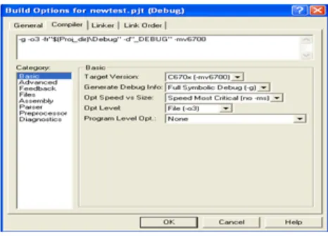
A. Hardware optimization
Figure 2. Build option with highest level of hardware optimization
B. Software optimization
Software optimization is the process of modifying a software system to make some aspect of it work more efficiently or use fewer resources. In general, a program is said to be optimized when it is executed more rapidly with less memory storage or when it draws less power. Several optimization schemes are used in fixed point and floating point implementations.
1) Function inlining
Function inlining is the process of replacing a function call with the body of the function itself [9]. To reduce the function call overhead, some of the smaller functions can be declared inline. The compiler substitutes the code wherever the function is called. This technique improves the execution time by eliminating function call and return overhead at the expense of larger code size.
inline void fft (struct buffer *input_data, int n, int m)
2) Loop unrolling
Loop unrolling is a loop transformation technique that attempts to optimize a program’s execution speed at the expense of its binary size [9]. The goal of loop unwinding is to increase program’s speed by reducing instructions that control the loop, such as pointer arithmetic and end of loop tests on each iterations, reducing branch penalties etc. Loops can be rewritten as a repeated sequence of similar independent statements eliminating this overhead.
for (i=0;i<row_length;i++) {
for (j=0;j<Number_Of_Filters;j+=4 ) {
co_eff->data[i][j]=log10(co_eff->data[i][j]); co_eff->data[i][j+1]=log10(co_eff->data[i][j+1]); co_eff->data[i][j+2]=log10(co_eff->data[i][j+2]); co_eff->data[i][j+3]=log10(co_eff->data[i][j+3]); }
VI.
SIMULATION RESULTS
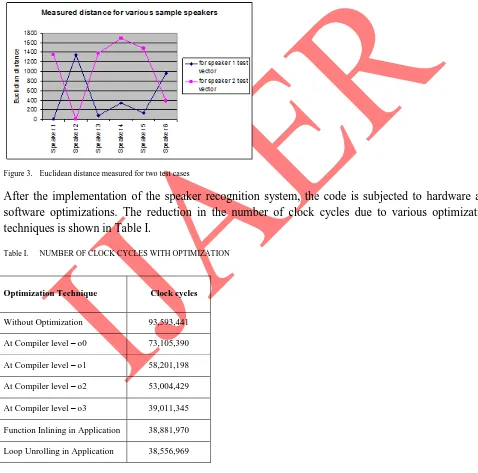
In the highlighted approach, feature extraction was done using MFCC algorithm. Further, mean square compression was applied to the extracted features. Speaker recognition was based on the distance between the feature vectors of the database and code book generated during the testing phase. Out of the 8 speakers included in our experiment, first 6 were trained and their code books were stored in the database. All the 6 trained speakers were identified correctly by the system and the 2 intruders were rejected. The experimental results for two test cases with speaker 1 and speaker 2 are shown in Fig. 3.
Figure 3. Euclidean distance measured for two test cases
After the implementation of the speaker recognition system, the code is subjected to hardware and software optimizations. The reduction in the number of clock cycles due to various optimization techniques is shown in Table I.
Table I. NUMBER OF CLOCK CYCLES WITH OPTIMIZATION
Optimization Technique Clock cycles
Without Optimization 93,593,441 At Compiler level – o0 73,105,390 At Compiler level – o1 58,201,198 At Compiler level – o2 53,004,429 At Compiler level – o3 39,011,345 Function Inlining in Application 38,881,970 Loop Unrolling in Application 38,556,969
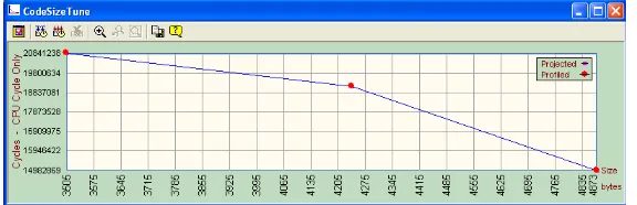
negatively or positively. Our implementation is having a code size of 3504 bytes. The total number of CPU cycles can be improved if the code size can be compromised.
Figure 4. Comparison between CPU cycles and Code size
VII. CONCLUSION
Significant advances in speaker recognition owes to the progress in the areas of acoustic-phonetics, speech perception, linguistics, and psychoacoustics. Such systems need to have an efficient way of representing, storing, and retrieving information required for natural conversation. The implementation of speaker recognition system on TMS320C6713 DSP board has been presented. Through analysis, we found out that embedded system development for signal processing is efficient with the help of Digital Signal Processors. The Code Composer Studio can provide various levels of hardware optimization. Also, software optimization can be achieved by incorporating some features to the source code. Hence, we conclude that the proposed implementation has a potential for shorter development time while maintaining low cycle counts.
REFERENCES
[1] Ben Gold, Nelson Morgan, “Speech and Audio Signal Processing”, Wiley- India Edition,
[2] Thomas.F. Quatieri, “Discrete Time Speech Signal Processing: Principles and Practice”,
Pearson Education, 2009.
[3] Wael Al-Sawalmeh, Khaled Daqrouq, Omar Daoud, Abdel-Rahman Al-Qawasmi, “Speaker
Identification System-based Mel Frequency and Wavelet Transform using Neural Network Classifier”, European Journal of Scientific Research, April 2010.
[4] Sujay Phadke, Rhishikesh Limaye, Siddharth Verma, Kavitha Subramanian, “On Design and
Implementation of an Embedded Automatic Speech Recognition System”, IEEE Proceedings of 17th International conference on VLSI Design, 2004.
[5] L. R. Rabiner, R. W. Schafer: “Digital Processing of Speech Signals”, Pearson Education, 2009.
[6] Md Rashidulhasan, Mustafa Jamil, Md.Golam Rabbani, Md Saifur hRahman, “Speaker
Identification using Mel Frequency Coefficients”,3rd International Conference on Electrical & Computer Engineering, ICECE 2004, Dhaka, Bangladesh.
[7] Joseph P. Campbell: “ Speaker recognition” Department of Defence, Fort Meade.
Wiley, New York, 2005.
[10] Texas Instruments, TMS320C6713 Digital Signal Processor Optimized for High Performance
Multichannel Audio Systems, Application Report SPRA921 - June 2003
[11] H. B. Kekre1, Ms. Vaishali Kulkarni, “Speaker Identification by using Vector Quantization”,
International Journal of Engineering Science and Technology, Vol. 2(5), 2010, 1325-1331