ORIGINAL ARTICLE
City-Bus-Route Demand-based Efficient
Coupling Driving Control for Parallel Plug-in
Hybrid Electric Bus
Qin‑Pu Wang
1, Chao Yang
2, Ya‑Hui Liu
2*and Yuan‑Bo Zhang
2Abstract
Recently, plug‑in hybrid electric bus has been one of the energy‑efficient solutions for urban transportation. However, the current vehicle efficiency is far from optimum, because the unpredicted external driving conditions are difficult to be obtained in advance. How to further explore its fuel‑saving potential under the complicated city bus driving cycles through an efficient control strategy is still a hot research issue in both academic and engineering area. To realize an efficient coupling driving operation of the hybrid powertrain, a novel coupling driving control strategy for plug‑in hybrid electric bus is presented. Combined with the typical feature of a city‑bus‑route, the fuzzy logic inference is employed to quantify the driving intention, and then to determine the coupling driving mode and the gear‑shifting strategy. Considering the response deviation problem in the execution layer, an adaptive robust controller for electric machine is designed to respond to the transient torque demand, and instantaneously compensate the response delay and the engine torque fluctuation. The simulations and hard‑in‑loop tests with the actual data of two typical driving conditions from the real‑world city‑bus‑route are carried out, and the results demonstrate that the pro‑ posed method could guarantee the hybrid powertrain to track the actual torque demand with 10.4% fuel economy improvement. The optimal fuel economy can be obtained through the optimal combination of working modes. The fuel economy of plug‑in hybrid electric bus can be significantly improved by the proposed control scheme without loss of drivability.
Keywords: Hybrid electric vehicle, Single‑shaft parallel electromechanical powertrain, Coupling driving mode, Adaptive robust control
© The Author(s) 2018. This article is distributed under the terms of the Creative Commons Attribution 4.0 International License (http://creat iveco mmons .org/licen ses/by/4.0/), which permits unrestricted use, distribution, and reproduction in any medium, provided you give appropriate credit to the original author(s) and the source, provide a link to the Creative Commons license, and indicate if changes were made.
1 Introduction
As representative of new energy vehicles, plug-in hybrid electric vehicle is always a hot topic in the field of recent vehicle technology [1]. Especially in areas of urban pub-lic transport, the excellent performance of low energy consumption and low emissions makes the plug-in hybrid electric bus (PHEB) become the primary solu-tion [2, 3]. Recently, with the applicasolu-tion of the idle-stop technology [4], the all-electric range of PHEB might be extended by utilizing more pure electric driving [5]. Con-sidering the traffic congestion in the big city of China,
the vehicle launch and accelerating condition might fre-quently appear in the driving cycles of the city bus [6]. However, in most cases the electric energy stored in the PHEB might not cover the whole city-bus-route, the optimal coordinated operation between the engine and the electric machine (EM) is very worthy of study [7]. Because of the configuration features, the coordinated control becomes very difficult especially for the single-shaft parallel hybrid powertrain with the automated mechanical transmission (AMT) [8–10]. To solve this problem, several solutions have been presented for real-time optimization of the steady-state energy flows uti-lizing dynamic programming presented by Li et al. [11] and Lin et al. [12], equivalent consumption minimization strategy presented by Yang et al. [13] and Geng et al. [14], or model predictive control (MPC) strategy presented by
Open Access
*Correspondence: [email protected]
2 State Key Laboratory of Automotive Safety and Energy, Tsinghua University, Beijing 100084, China
Yan et al. [15]. Nevertheless, the transient process, such as the complicated electromechanical coupling working mode and the multi-modes transition, was not consid-ered in these control strategies.
During a vehicle launch and accelerating process, PHEB might fulfill an electromechanical coupling-driv-ing mode after a pure electric drivcoupling-driv-ing mode to ensure the operation efficiency until the engine torque satis-fies the demand torque on a high efficient zone [16–18]. Therefore, the coupling driving mode, which refers to the hybrid driving mode or the engine active charging mode, is crucial for the vehicle launch and accelerating process of PHEB [16].
Considering the difference between dynamic char-acteristics of the engine and the EM, it is necessary to further study the coordinated control method for an efficient solution of the hybrid powertrain. Therefore, a novel torque-demand control approach based on the MPC was proposed by He et al. [19], to implement the torque control of parallel hybrid powertrain. In addi-tion, for a parallel hybrid powertrain, the coordinated control method using dynamic input allocation, MPC, and sliding mode control method presented by Cordiner et al. [20], Minh et al. [21], and Metin et al. [22], respec-tively. Using the fast response behavior of the EM, an electromechanical coupling driving control scheme was proposed by Yang et al. [23, 24] to achieve good torque tracking performance.
The coordinated control strategies can ensure the torque tracking performance during a coupling driv-ing process. However, the instantaneous variation of the traffic flows, road conditions, and the passenger loads in a city-bus-route, might greatly affect the robustness of the control system. To adaptively deal with the stochastic driving intention, a city-bus-route demand-based cou-pling driving control approach is designed for the single-shaft parallel PHEB with AMT. Firstly, the time-varying driving intention is quantified with a fuzzy logic, and then the coupling driving mode and the AMT gear-shift-ing strategy are determined with a strategy determination module. Secondly, considering the dynamic characteris-tics of the EM, the adaptive robust controller is designed for the EM to respond to the transient torque demand. Meanwhile, the response deviation and the transient fluctuation of the engine torque are compensated with the fast response behavior of the EM.
The rest of the paper is organized as follows: Section 2 gives the models of the single-shaft parallel PHEB. The efficient coupling driving control approach is developed in Section 3. The results of simulation and hard-in-loop (HIL) test are given in Section 4. Finally, the conclusion and discussion are given in Section 5.
2 Model Descriptions
A typical single-shaft parallel hybrid powertrain is illus-trated as Figure 1.
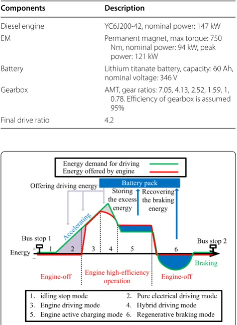
As shown in Figure 1, the EM is placed between the output of clutch and the input of AMT, and the clutch could implement the mode transition of this powertrain with engagement and disengagement operations. AMT could assist the vehicle to adapt to the demand from dif-ferent conditions, and help the engine and the EM to work in their efficient zones as well. Furthermore, the parameters of the studied PHEB are shown in Table 1.
2.1 Energy Demand Analyses of City Bus Route
During the operation, PHEB with that powertrain could fulfil six basic working modes, including idling stop mode, pure electrical driving mode, engine driv-ing mode, hybrid drivdriv-ing mode, engine active chargdriv-ing mode, and regenerative braking mode. The diagram of the PHEB energy demand corresponded to the working modes mentioned above is shown in Figure 2. As shown in Figure 2, between two bus stops, the expected engine operation in PHEB might contain two states, engine-off and engine high-efficiency operation. The engine-engine-off state occurs at the idling stop mode, pure electrical driv-ing mode, and the regenerative brakdriv-ing mode. With the increasing driving demand torque the engine will be started and engaged into the driveline. Then the prob-lem of fuel saving becomes the optimization probprob-lem of engine working points. It should be noted that the EM might be utilized to assist the engine running in its high-efficiency area both in the hybrid driving mode and the engine active charging mode. Thus, those two modes are very important for improving the fuel economy of PHEB.
2.2 Diesel Engine Model
The simplified model of the diesel engine is employed for the torque control, which could be shown in Figure 3.
Diesel engine
EM Controller
Battery pack AMT
EM
Clutch Plug-in
Actuator
In Figure 3, φ represents the accelerator pedal posi-tion. Je is the moment of inertia of the crankshaft; ωe is
the rotational speed of the crankshaft; φ(dωe/dt) is the
dynamic compensation factor; ke and τe are the
propor-tional coefficient and the time constant, respectively; Te
and TL are the effective torque and the load torque of the
engine, respectively; Tes is the static torque of the engine,
which could be obtained from the engine map; ΔTe
rep-resents a dynamic correction item of the engine torque, which could be described as follows:
Only considering the rotational dynamics of the crank-shaft, the engine model could be written as follows:
2.3 EM Model
The control-oriented dynamic model of the EM con-sists of two modes: the driving mode and the generating mode. In order to realize the transient torque tracking control, the axis models are employed, when the EM operates in the driving mode:
When the EM operates in the generating mode:
where id and iq are the d and q axis stator currents,
respectively; ud and uq are the d and q axis stator
volt-ages, respectively; Rs, L, P and Φ represent the stator
resistance, the stator inductance, the number of the pole pairs, and magnet’s flux linkage, respectively; Jm and Bμ
are the moment of inertia of the EM output shaft and the damping coefficient, respectively; Te is the engine torque
when the PHEB runs in the active charging mode, and Tm
is the EM torque, which can be described as the following equation:
3 City‑Bus‑Route Demand‑based Efficient Coupling Driving Control Strategy
In this section, a novel city-bus-route demand-based coupling driving control strategy is presented. Firstly, the fuzzy logic controller quantifies the driver’s driving intention. Then the AMT gear-shifting strategy and the coupling driving mode are determined with the quanti-fied driving intention in the strategy determination mod-ule. Secondly, the designed PI controller for engine and adaptive robust controllers for EM implement the torque tracking control in the coupling driving mode. Moreover,
(1)
�Te=Je dωe
dt ·ϕ
dωe
dt
.
(2)
Jeω˙e=Te−TL,
Te=Tes−�Te−f1(dφ/dt).
(3)
dωm
dt = Jm1Tm− Bµ
Jmωm− Jm1Tl,
did
dt = − Rs
Lid+Pωmiq+L1ud,
diq
dt = − Rs
Liq−Pωmid−PΦL ωm+ 1Luq.
(4)
dωm
dt = J1mTe− 1
JmTm−
Bµ
Jmωm− 1
JmTl, did
dt = − Rs
Lid+Pωmiq−L1ud,
diq dt = −
Rs
Liq−Pωmid+PΦL ωm− 1Luq,
(5)
Tm=
3 2PΦiq. Table 1 Parameters of HEB powertrain
Components Description
Diesel engine YC6J200‑42, nominal power: 147 kW EM Permanent magnet, max torque: 750
Nm, nominal power: 94 kW, peak power: 121 kW
Battery Lithium titanate battery, capacity: 60 Ah, nominal voltage: 346 V
Gearbox AMT, gear ratios: 7.05, 4.13, 2.52, 1.59, 1, 0.78. Efficiency of gearbox is assumed 95%
Final drive ratio 4.2
Figure 2 Diagram of the energy demand of studied PHEB
considering the properties of the single-shaft parallel hybrid powertrain, the response error of engine torque is compensated by the accurate EM torque control to guar-antee the torque tracking performance of powertrain.
3.1 Fuzzy Logic Inference for Driving Intention
The driving intention is generated from the driver’s maneuvers during the PHEB accelerating process. How-ever, it is difficult to describe the intention accurately by the mathematical expressions. Therefore, the fuzzy logic based on the test data and experience is adopted to implement the quantification of the driving inten-tion. Diagram of the fuzzy logic controller is shown in Figure 4.
As shown in Figure 4, the input variables are vehicle speed vveh, the relative accelerator pedal position φrel, and
the absolute value of the change rate of accelerator pedal position dφ/dt, the output variable is driving intention Id.
The relative accelerator pedal position could be obtained by the equation as follows:
where φ is actual accelerator pedal position, φequ is
equi-librium accelerator pedal position reflecting the accel-erator pedal position which maintains the vehicle driving on flat road with a uniform speed, and the value of φequ
might be obtained through looking up the steady-state table with the inputs of the engine torque and the engine rotational speed, and the engine torque could be obtained by the vehicle longitudinal dynamics equation as follows:
where Ff and Fw are the rolling resistance and the
aerody-namic drag, respectively. r, ηT, ig, and if are wheel radius,
transmission efficiency, AMT gear ratio, and differential ratio, respectively.
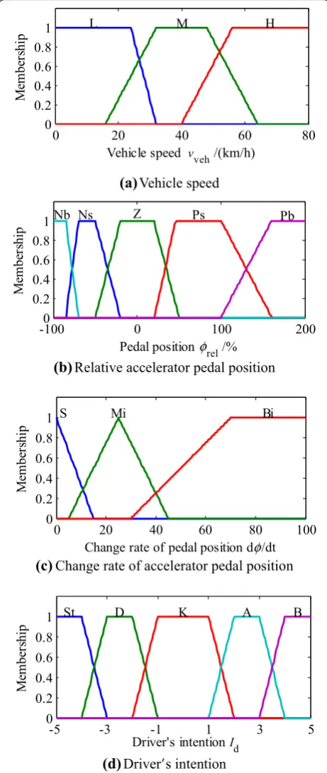
According to the test data of actual vehicle, the fuzzy logic rule base shown in Table 2 can be obtained. In Fig-ure 5, the memberships of vveh are L, M, and H, which
represent the low speed, the middle speed, and the high
(6) φrel= 100×
φ−φequ
φequ ,
(7) Te=(Ff+Fw)rηTigif,
speed, respectively. The memberships of frel are Nb, Ns,
Z, Ps, and Pb, which are the negative big, the negative small, the zero, the positive small, and the positive big of the equilibrium accelerator pedal open, respectively. The memberships of df/dt are S, Mi, and Bi, which are the small, the middle, and the big of the change rate of accelerator pedal open, respectively. Moreover, the out-put variable Id obtained by the defuzzification are
quanti-fied as St, D, K, A, and B, which represent the intention of stop, decelerating, keep, accelerating, urgent accelerating.
3.2 Balanced AMT Gear‑shifting Strategy and Driving Mode Determination Module
The double-parameters balanced AMT gear-shifting strategy (BGS), which balances the dynamic gear-shifting (DGS) maneuver and the economic gear-shifting (EGS) maneuver, is employed. This strategy tends to dynamic or economic depending on the driving intention, which could be quantified by the designed fuzzy inference. Taking the effects of engine operating points for exam-ple, the full DGS ensures that engine might work on the external characteristic line, and the full EGS reflects that engine would work on the optimal operating line with the highest efficiency. According to the quantified driv-ing intention, the AMT gear-shiftdriv-ing maneuver might be determined that the gear-shifting maneuver tends to DGS with urgent accelerating intention and conversely tends EGS with keep and normal accelerating intention. Therefore, the energy-efficient operation of PHEB with-out drivability loss might be fulfilled by the proposed gear-shifting strategy.
Fuzzy logic inference Fuzzification
Defuzzification Fuzzy
rule base
Equation (7)
Equation (6) φrel Id
φ
φ
φ
equ
d dt u d dt veh
v Te
e
ω
g f i i r
Figure 4 Diagram of the fuzzy logic controller
Table 2 Fuzzy logic rule base Relative pedal
open φrel
Change rate of accelerator
pedal position dφ/dt Vehicle speedvveh(km/h)
S M H
Nb S St D D
Mi St D D
Bi St D D
Ns S St K K
Mi St D D
Bi St D D
Z S St St K
Mi St K K
Bi St K K
Ps S A K K
Mi A A A
Bi B B B
Pb S A A A
Mi A A A
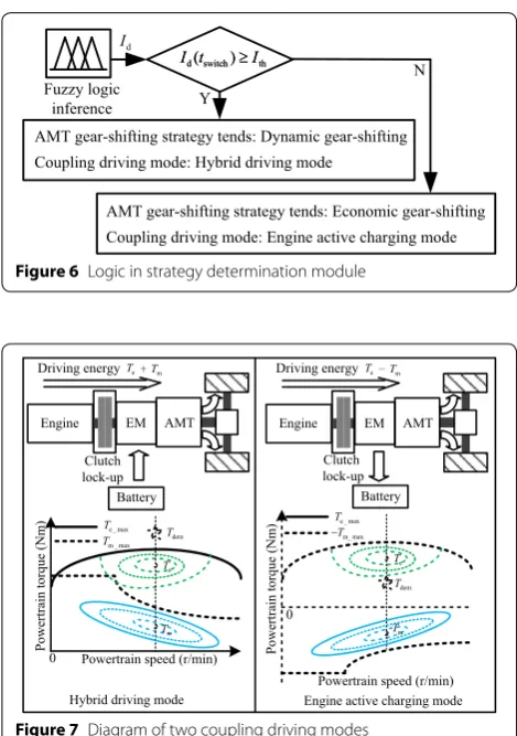
Combined with the quantified driving intention, the AMT gear-shifting strategy and the mode selection dur-ing the coupldur-ing drivdur-ing mode can be determined, the logic of which is shown in Figure 6. In Figure 6, Id(tswitch)
is the driving intention when the engine engages into the driveline at the time tswitch, and Ith represents the logic
threshold of driving intention, and its value could be obtained by repeated tests.
According to the description of PHEB working modes, the coupling driving modes can ensure the efficient oper-ation of PHEB. As shown in Figure 7, the engine work-ing points are improved into its high-efficiency area by EM in the coupling driving modes. However, during the simultaneous operation of engine and EM, the differ-ence of dynamic characteristics between the engine and the EM causes the torque deviation of powertrain, which might significantly influence the drivability of PHEB. In this paper, the coordinated control scheme utilizes the EM to compensate the torque response deviation. Thus, the EM controller is very important that some uncertain-ties should be taken into account in the controller design. Then the design of the torque controllers for the engine and EM will be given in the next two parts.
3.3 PI torque Controller for Diesel Engine
In order to response the demand torque, a PI torque con-troller is designed. The expression can be written as:
where ueng is the engine control input that represent the
fuel injection quantity, Ter is demand powertrain speed, kp, ki are proportional and integral gains, respectively.
3.4 Adaptive Robust Controllers for the EM Torque Tracking Control
To ensure the torque balance of the whole powertrain, the EM control system design might become the chief task. Then the objective of EM controller becomes that ensures the accurate trajectory tracking control with the existence of model uncertainties and external distur-bances. First, the error models of EM in the driving mode and generating mode are necessary. Therefore, the error variables can be defined as follows:
where x and x¯ are the error variables when the EM works in the driving mode and generating mode, respectively.
ωmr , idr, iqr are the desired values of the EM speed, the (8) ueng=kp
Ter−Te
+ki
Ter−Te dt,
(9) x=
x1 x2 x3T
=
ωm−ωmr id−ird iq−irqT,
¯
x=
¯
x1 x¯2 x¯3T
=
ωm−ωm∗ id−i∗d iq−i
∗
qT,
(b)
Relative accelerator pedal position(c)
Change rate of accelerator pedal position(d)
Driver’s intention-1000 0 100 200
0.2 0.4 0.6 0.8 1
Pedal position rel /%
Me
mb
er
sh
ip
Ns Z Ps
Nb Pb
0 20 40 60 80 100
0 0.2 0.4 0.6 0.8 1
Change rate of pedal position dφ φ
/dt
Me
mb
er
sh
ip
S Mi Bi
-5 -3 -1 1 3 5
0 0.2 0.4 0.6 0.8 1
Driver's intention Id
Me
mb
er
sh
ip
St D K A B
(a)
Vehicle speed0 20 40 60 80
0 0.2 0.4 0.6 0.8 1
Vehicle speed vveh /(km/h)
Me
mb
er
sh
ip L M H
d-axis, and the q-axis stator currents when the EM oper-ates in the driving mode, respectively. ωm* , id*, iq* are the
desired values of the EM speed, the d-axis, and the q-axis stator currents when the EM operates in the generat-ing mode, respectively. Combingenerat-ing with the EM model described in Eqs. (3) and (4), the error equations that have considered the uncertainties can be defined when EM operates in the driving mode:
When EM operates in the generating mode:
where the uncertainty parameters θ1, θ2, τ1, and τ2 are
given as follows:
(10)
˙
x1= 32PΦJmx3−θ1x1− ˜θ1ωrm−w1, ˙
x2= −θ2x2+P(x1x3+x1irq+ωmrx3)+u1, ˙
x3= −θ2x3−P(x1x2+ωrmx2)−PΦL x1− ˜θ2irq+u2.
(11)
˙¯
x1=TE−32PJΦ
mx3¯ −τ1x1¯ − ˜τ1ω ∗
m−w2,
˙¯
x2= −τ2x2¯ +P(x1¯ x3¯ +e1i∗q+ωm∗x3¯ )+u3,
˙¯
x2= −τ2x3¯ −P(x1¯ x2¯ +ω∗mx2¯ )+PLΦx1¯ − ˜τ2i
∗
q+u4,
˜
θi and τ¯i(i = 1, 2) are the error between the uncertain
parameters and the adaptive estimated value, which would be described in later part. Moreover, w1, w2
rep-resent the load disturbances of EM control system. Then the performance vectors are defined as follows:
where ρi and ρ¯i (i = 1, 2, 3) are the weighting factors. TE
is an error term. Moreover, u1, u2, u3, u4 are equivalent
control inputs described as follows:
Then the control objective of EM controller becomes that the closed-loop system is stable with L2-gain, that is,
when w ≠ 0, the system from the disturbance inputs wi
(i = 1, 2) to the penalty outputs z and z¯ has finite L2-gain not larger than γi (i = 1, 2).
where T > 0 is any given scalar. γi (i = 1, 2) are the
evalu-ating factors. Thus, regarding the system described in Eqs. (10) and (11), an adaptive robust controller for EM is designed when EM operates in the driving mode:
And the parameter adaptive update laws are chosen as
(12)
θ1= BµJm,θ2= RLs,
τ1= BµJm,τ2= RLs,
(13)
z= [ρ1x1 ρ2x2 ρ3x3]T, ¯
z= [ ¯ρ1x¯1 ρ¯1x¯1 ρ¯1x¯1]T,
(14)
u1=Pωrmirq+ 1Lud,
u2= ˆθ2irq− PΦ
L ωmr − ˙irq+1Luq,
(15)
u3=Pω∗mi∗q− 1Lud,
u4= ˜τ2i∗q+ PLΦω
∗
m− ˙i∗q−L1uq,
(16)
T
0 �z(t)�2dt≤γ1 T
0 �w1(t)�2dt, ∀w1, T
0 �¯z(t)�2dt≤γ2 T
0 �w2(t)�2dt, ∀w2,
(17)
u1= ˆθ2x2−P(x1x3+x1iqr+ωrmx3)−k2x2,
u2= �
PΦ L −
3PΦ 2Jm
�
x1+ ˆθ2x3+P(x1x2+ωrmx2)
+∂α1 ∂x13P
Φ 2Jmx3−
∂α1 ∂x1θˆ1x1−
∂α1 ∂x1θˆ2+
∂α1 ∂θˆ1
˙ˆ θ1
− 1
2γ12 Z1
� ∂α1 ∂x1
�2
−k3Z1.
(18)
˙ˆ θ1=χ1
� ∂α1
∂x1x1Z1−x 2
1−ωrmx1+ ∂α∂x11ωrmZ1 �
,
˙ˆ
θ2=χ2(−x3Z1−x22−irqZ1).
Figure 6 Logic in strategy determination module
When EM operates in the generating mode:
And the parameter adaptive update laws are chosen as
where ki(i = 1, 2, 3) and k¯i(i=1, 2, 3) are adjustable parameters of the controller, Z1=x3−α1(x1,θˆ1) and Z2= ¯x3−α2(x¯1,τˆ1) , α1(x1,θˆ1) and α2(x¯1,τˆ1) are virtual controllers which could be chosen as follows:
In addition, χi(i = 1, 2) and βi(i = 1, 2) are adjustable
parameters of adaptive laws.Taking the driving mode of EM for example, the adaptive robust controller described in Eqs. (17) and (18) might be designed by the close-loop system Lyapunov stability analysis. First, a positive defi-nite Lyapunov function is defined as follows:
Then, its time derivative could be calculated as follows:
Remark: For the external disturbance w1, the inequality
transform might be used which can be written as follows:
(19)
u3= ˆτ2x2¯ −P(x1¯ x3¯ + ¯x1iq∗+ω∗mx3¯ )− ¯k2x2¯ , u4=
� 3PΦ
2Jm − PΦ
L �
¯
x1+P(x¯1x¯2+ω∗mx¯2) + ˆτ2x2¯ −PLΦx1¯ + ∂α∂x¯21TE−
∂α2
∂x¯1
3PΦ 2Jmx3¯
−∂α2
∂x¯1τˆ1x1¯ +
∂α2
∂τˆ1τ˙ˆ1− ¯k3Z2.
(20)
˙ˆ τ1=β1
∂α2 ∂x¯1x¯1Z2+
∂α2 ∂x¯1ω
∗
mZ2− ¯x21−ω∗mx¯1
,
˙ˆ
τ2=β2(−¯x3Z2− ¯x22−i∗qZ2),
(21)
α1(x1,θˆ1)= 32PJmΦ �
ˆ
θ1x1−k1x1−2γ12 1
x1 �
,
α2(x¯1,τˆ1)= 32PJmΦ �
TE− ˆτ1x¯1+ ¯k1x¯1+2γ12 2 ¯ x1 � . (22) V = 1
2x 2 1+ 1 2x 2 2+ 1 2Z 2 1+ 1 2 ˜
θTΓ−1θ˜.
(23) V =x1
3PΦ
2Jm
x3−θ1x1− ˜θ1ωmr −w1
+x2[−θ2x2+P(x1x3+x1irq+ωrmx3)+u1]
+Z1[−θ2x3−P(x1x2+ωrmx2)− PΦ
L x1− ˜θ2i r q+u2
− ∂α1
∂x1
3PΦ
2Jm
x3−θ1x1− ˜θ1ωrm−w1
−∂α1
∂θˆ1
˙ˆ θ1 . (24)
−x1w1≤ 2γ12 1
x21+γ12 2w21,
∂α1 ∂x1w1Z1≤
γ12
2w12+ 2γ12 1
Z12�∂α1∂x 1
�2
.
Choosing the adaptive robust controller described in Eqs. (17) and (18), and combining Eq. (24), Eq. (23) might become as follows:
where the adjustable gains ki(i = 1, 2, 3) should satisfy the
conditions as follows:
Therefore, combing with the LaSalle invariant set prin-ciple, it can be concluded that the designed controller can achieve the mentioned above control objectives. Because the adaptive controller described in Eqs. (19) and (20) for the generating mode of EM is deduced that is similar with that of the driving mode of EM, so the proof proce-dure will be omitted here.
4 Validation Results and Analysis
The simulation and HIL tests are performed on a single-shaft parallel PHEB in MATLAB/Simulink. Basic param-eters are listed in Table 1. Moreover, control paramparam-eters in Table 3 are selected among all parameters obtained from repeatedly debugging model with the proposed method. These selected parameters can show the best control performance.
To verify the effectiveness of the proposed con-trol approach, a driving condition of city-bus-route 613 in Chongqing, China, is selected as the simulation condition.
A road section of city-bus-route is extracted from KongGang-Square station to YuBei-Broadcast station that the vehicle speed and the road grade information are shown in Figure 8. It should be noted that, the grade
(25) ˙
V ≤ −
k1−1
2ρ1
x21−
k3−1
2ρ3
Z12
−
k2−
1 2ρ2
x22+γ12w12− 1 2z
Tz,
(26)
k1≥ 1
2ρ1,k2≥ 1 2ρ2,k3≥
1 2ρ3.
Table 3 Control parameters
Parameter Value Parameter Value
kp 0.9 ¯k3 7.5
ki 9.1 χ1 0.759
k1 0.62 χ2 0.317
k2 11.6 β1 0.561
k3 23.5 β2 0.232
¯
k1 0.06 γ1 0.92
¯
changes with the distance, so generally the grade-dis-tance curve is used to reflect the grade information of a road section.
4.1 Driving Intention Quantification
To verify the intention recognition, the accelerator pedal position and the actual gear position curve were collected from the driving condition as shown in Figure 9.
As shown in Figure 9, two sections of routes are with fully different driver’s maneuvers. The first section from 0 s to 117 s shows the higher acceleration and the larger pedal open than that of the second section from 120 s to 300 s. Therefore, the quantified driving intention is shown as in Figure 10. The result shows that the inten-tion could essentially reflect the actual maneuver. More-over, the urgent accelerating intention appears in 4.5 s and the rest is the normal accelerating intention. There-fore, the threshold of Ith could be selected as 3.2. Because
the focus in this paper is the process of PHEB driving mode, two vehicle launch process are extracted from the selected driving condition and the results are shown in Sections 4.2 and 4.3.
4.2 Results under Different Driving Intentions
A clear city-bus-route without traffic jams is simulated in this part. The driver’s intention under this condition inclines to drive through this section of road fast, so according to the strategy determination described in Sec-tion 3.2, the simulation results are shown in Figure 11.
As shown in Figure 11(a), the results of vehicle speed obtained from the simulation are close to the test data, and the deviation reflects the error between simulation
model and actual vehicle. With the increasing vehicle speed, the AMT will execute the gear shifting opera-tion in accordance with BGS strategy. The engine torque tracking performance can be ensured, which is shown in Figure 11(c). The designed adaptive robust controller can respond to the demand EM torque quickly and accu-rately, as shown in Figure 11(d).
A congested city-bus-route is simulated to reflect the driver maneuvers with the intention Id(tswitch) < Ith. The
simulation results are shown in Figure 12. As shown in Figure 12(a), the vehicle speed of simulation is in accord-ance with the test data, and with the intention of slow driving, Figure 12(c) shows that the engine demand torque is elevated by the generating torque of EM in the driving condition of the low torque demand. In addi-tion, due to the engine response characteristics, the PI controller with the control input of fuel injection cannot eliminate the torque deviation. However, the proposed coupling driving control approach utilizes the EM torque to compensate the above torque deviation, and the good tracking performance is ensured by the designed adap-tive robust controller for EM, the effect curves of which is shown in Figure 12(d). Therefore, it can be concluded that the efficient operation of PHEB is ensured. It should be noted that Figure 11 and Figure 12 show two differ-ent driving conditions with relevant driving intdiffer-entions. Under urgent driving condition, the test vehicle uses less time than that under slow driving condition, when it reaches the same speed. Thus, the timeline in Figure 11 shows less than that in Figure 12.
The working points of engine and EM in two differ-ent driving intdiffer-entions are shown in Figure 13. As seen (a) Speed-time curve
(b)Grade-distance curve
0 50 100 150 200 250 300
0 20 40
Time t/s
Sp
ee
d
vveh
/(km/h
)
0 200 400 600 800
-4 -2 0 2 4
Distance /m
Gr
ad
e
/%
Figure 8 Curves of the studied simulation scenario
(a) Actual pedal position
(b)Actual gear position
0 50 100 150 200 250 300
0 50 100
Time t/s
Pe
da
l pos
ition
φ
/%
0 50 100 150 200 250 300 2
3 4 5
Time t/s
G
ear
ig
in Figure 13, the working areas of engine and EM are improved by the coupling driving mode, especially in engine active charging mode, the working points of engine are moved into its high-efficiency area. To show the improvement of working points more clearly, the areas plot by the red dotted line are defined as the high-efficiency areas of engine and EM. The results show that the working points of engine and EM are greatly improved by the proposed control strategy.
4.3 HIL Test Results
To verify the real-time capability of the proposed control method, the HIL test is carried out. The HIL test plat-form is shown in Figure 14.
0 50 100 150 200 250 300 -5
0 5
Time t/s
In
te
ntion
Id
Figure 10 Result of driving intention
(a) Vehicle speed
(b) Gear position
(c) Engine torque tracking curves
(d)EM torque tracking curves
0 5 10 15 20 25
0 10 20 30 40
Time t/s
Sp
ee
d
vveh
/(km/h
)
Test data Simulation
0 5 10 15 20 25
1 2 3 4 5 6
Time t/s
Gear
ig
5 10 15 20 25
0 200 400 600
Time t/s
Engine
to
rq
ue
Te
/N
m
Demand Actual
5 10 15 20 25
0 100 200 300 400
Time /s
EM
to
rq
ue
TEM
/N
m
Demand Actual
Figure 11 Simulation results (intention of urgent driving)
(a) Vehicle speed
(b) Gear position
5 10 15 20 25 30
0 10 20 30 40
Time t/s
Sp
eed
vveh
/(km/h
)
Test data Simulation
0 5 10 15 20 25 30
1 2 3 4 5
Time t/s
Gear
ig
25 30
0 200 400 600
Time t/s
Engine
to
rq
ue
Te
/N
m
Demand Actual
(c) Engine torque tracking curves
(d)EM torque tracking curves
5 10 15 20 25 30
-400 -200 0 200 400
Time t/s
EM
to
rq
ue
TEM
/N
m
Demand Actual
As shown in Figure 14, the dSPACE real time test sys-tem is employed for running the vehicle model. Hybrid control unit (HCU) is the actual controller used in PHEB. The PHEB model built in MATLAB/Simulink are loaded into dSPACE through real time interface (RTI). The C codes of proposed control strategy is generated with the auto code function of real time workshop (RTW), mean-while, the controller drive program is compiled with the main program in Tasking EDE tool. A PC is employed with control desk to monitor the test operation. The test is carried out in Chinese typical urban condition and its results are shown in Figure 15.
The outstanding vehicle speed tracking performance and the reasonable torque spilt effect can be shown in Figure 15, which proves the proposed control strategy is effective to the real time HIL test. To further show the advantage, a rule-based control strategy is adopted as the baseline strategy, which is commonly used in actual vehi-cle [19]. The FC and EC represent the fuel consumption
and the electricity consumption, respectively. The aver-age brake specific fuel consumption (BSFC) results reflect the improvement of working points. As shown in Table 4, the fuel consumption improvement is 10.4% under the given driving condition.
5 Conclusions
(1) The driving intention is recognized by the designed fuzzy logic inference.
(2) According to the quantified intention, the mode selection method in the coupling driving mode and AMT gear-shifting strategy given in the strategy determination module by the pre-set threshold. (3) The adaptive robust controller is designed for EM to
ensure the tracking effect with the uncertainties and disturbances.
(4) The proposed control approach could guarantee the torque tracking performance, and the fuel economy can be improved 10.4% through adjusting the engine working points under different driving intentions. (5) The real time capability of the control approach has
been validated by HIL tests. The proposed control method has the potential to apply in the actual vehicle. 198 201 209
215225 235
235 250
261
261 275
275
Engine speed ωe/(r/min)
En
gine
to
rq
ue
Te
/N
m
1000 1500 2000 200
400 600 800
Unit:g/kWh
0.72 0.78 0.8
0.80.82 0.84
0.86
0.86 0.9 0.9 0.92
0.92
EM speed ωEM/(r/min)
EM
to
rq
ue
TEM
/N
m
0 1000 2000 -500
0 500
(a)Working points with the intention of urgent driving
198 206
215 215
225
225 235
235 250
261
275 275
Engine speed ωe/(r/min)
En
gine
to
rq
ue
Te
/N
m
1000 1500 2000 200
400 600 800
0.72 0.82
0.82
0.82 0.86 0.86 0.920.92
EM speed ωEM/(r/min)
EM
to
rq
ue
TEM
/N
m
0 1000 2000
-500 0 500
Unit:g/kWh
(b)Working points with the intention of slow driving
Figure 13 Simulation results of working points
Compile
Download
Control desk
Communication wires (CAN1/2)
HCU
RTW
C. Code
Drive program
RTI
Tasking EDE HIL test system
Matlab/Simulink PHEB model Control strategy Load
Figure 14 HIL test platform
0 200 400 600 800 1000 1200
0 20 40 60
Sp
ee
d
vveh
/(km/h
)
0 200 400 600 800 1000 1200
-1000 0 1000
To
rque
T
/N
m
0 200 400 600 800 1000 1200
0 1000 2000
Time t/s
Sp
ee
d ω
/(r/
min
)
Engine EM
Demand Actual
Engine EM
Figure 15 Test results under Chinese typical urban condition
Table 4 Comparison results of two control strategy
Strategy FC (L) Improvement (%) Average
BSFC(g/ kWh)
Rule‑based 1.25 ‒ 228.23
Authors’ Contributions
Q‑PW and CY were in charge of the whole trial; CY wrote the manuscript; Y‑HL and Y‑BZ assisted with sampling and laboratory analyses. All authors have read and approved the final manuscript.
Author details
1 Zhongtong Bus Hold Co., Ltd., Liaocheng 252000, Shandong, China. 2 State Key Laboratory of Automotive Safety and Energy, Tsinghua University, Bei‑ jing 100084, China.
Authors’ Information
Qin‑Pu Wang, born in 1964, is the General Manager Assistant at Zhongtong Bus Hold Co., Ltd., China. He received his bachelor degree from Xi’an Highway Institute, China, in 1984. His research interests include design and manufacture of hybrid electric vehicle. E‑mail: [email protected].
Chao Yang, born in 1986, is currently a postdoctoral fellow at State Key Lab-oratory of Automotive Safety and Energy, Tsinghua University, China. He received his PhD degree on Control Science and Engineering from Yanshan University, China, in 2016. His research interests include energy‑efficient control strategy design for hybrid electric vehicles. E‑mail: [email protected].
Ya‑Hui Liu, born in 1980, is currently an associate professor at State Key Lab-oratory of Automotive Safety and Energy, Tsinghua University, China. He received his bachelor degree from Jilin University, China, in 2003 and PhD degree from Beihang University, China, in 2009, respectively. His research interests include vehicle system dynamics, steering system and driver‑vehicle system. E‑mail: [email protected].
Yuan‑Bo Zhang, born in 1990, is currently working at State Key Labora-tory of Automotive Safety and Energy, Tsinghua University, China. His research interests include regenerative braking control strategy for electrified vehicles. E‑mail: [email protected].
Competing Interests
The authors declare no competing financial interests.
Funding
Supported by National Natural Science Foundation of China (Grant No. 51605243), National Key Science and Technology Projects of China (Grant No. 2014ZX04002041), and 1‑class General Financial Grant from the China Postdoctoral Science Foundation (Grant No. 2016M590094).
Publisher’s Note
Springer Nature remains neutral with regard to jurisdictional claims in pub‑ lished maps and institutional affiliations.
Received: 14 December 2016 Accepted: 22 June 2018
References
[1] Yong Sun, Zi‑Lin Ma, Gong‑You Tang, et al. Estimation method of state‑of‑ charge for lithium‑ion battery used in hybrid electric vehicles based on variable structure extended kalman filter. Chinese Journal of Mechanical Engineering, 2016, 29(4): 717–726.
[2] Chao Yang, Liang Li, Si‑Xiong You, et al. Cloud computing‑based energy optimization control framework for plug‑in hybrid electric bus. Energy, 2017, 125: 11–26.
[3[ Liang Li, Si‑Xiong You, Chao Yang, et al. Driving‑behavior‑aware stochastic model predictive control for plug‑in hybrid electric buses. Applied Energy, 2016, 162: 868–879.
[4] Marcello Canova, Yann Guezennec, Steve Yurkovich. On the control of engine start/stop dynamics in a hybrid electric vehicle. ASME Transac-tions, Journal of Dynamic System, Measurement, and Control, 2009, 131(12), 061005: 1–12.
[5] Zheng Chen, Bing Xia, Chenwen You, et al. A novel energy management method for series plug‑in hybrid electric vehicles. Applied Energy, 2015, 145: 172–179.
[6] Chao Yang, Jian Song, Liang Li, et al. Economical launching and accel‑ erating control strategy for a single‑shaft parallel hybrid electric bus. Mechanical Systems and Signal Processing, 2016, 76‑77: 649–664. [7] Tian‑Heng Feng, Lin Yang, Qing Gu, et al. A supervisory control strategy
for plug‑in hybrid electric vehicles based on energy demand prediction and route preview. IEEE Transactions on Vehicular Technology, 2015, 64(5): 1691–1770.
[8] Hong‑Cai Li, Qing‑Dong Yan, Chang‑Le Xiang, et al. Analysis method and principle of dual‑mode electro‑mechanical variable transmission program. Chinese Journal of Mechanical Engineering, 2012, 25(3): 524–529. [9] Wei‑Da Wang, Li‑Jin Han, Chang‑Le Xiang, et al. Synthetical efficiency‑
based optimization for the power distribution of power‑split hybrid electric vehicles. Chinese Journal of Mechanical Engineering, 2014, 27(1): 58–68.
[10] Dongsuk Kum, Huei Peng, Norman Bucknor. Control of engine‑starts for optimal drivability of parallel hybrid electric vehicles. ASME Transac-tions, Journal of Dynamic System, Measurement, and Control, 2014, 135(3), 021020: 1–10.
[11] Liang Li, Chao Yang, Ya‑Hui Zhang, et al. Correctional DP‑based energy management strategy of plug‑in hybrid bus for city‑bus‑route. IEEE Transactions on Vehicular Technology, 2015, 64(7): 2792–2803. [12] Chan‑Chiao Lin, Huei Peng, Jessy‑W. Grizzle et al. Power management
strategy for a parallel hybrid electric truck. IEEE Transactions on Control Systems Technology, 2003, 11(6): 839–849.
[13] Chao Yang, Siyu Du, Liang Li, et al. Adaptive real‑time optimal energy management strategy based on equivalent factors optimization for plug‑in hybrid electric vehicle. Applied Energy, 2017, 203: 883–896. [14] Bo Geng, James‑K. Mills, Dong Sun. Energy management control
of microturbine‑powered plug‑in hybrid electric vehicles using the telemetry equivalent consumption minimization strategy. IEEE Transac-tions on Vehicular Technology, 2011, 60(9): 4238–4248.
[15] Feng‑Jun Yan, Jun‑Min Wang, Kai‑Sheng Huang. Hybrid electric vehicle model predictive control torque‑split strategy incorporating engine transient characteristics. IEEE Transactions on Vehicular Technology, 2012, 61(6): 2458–2467.
[16] Li Chen, Gang Xi, Jing Sun. Torque coordination control during mode transition for a series‑parallel hybrid electric vehicle. IEEE Transactions on Vehicular Technology, 2012, 61(7): 2936–2949.
[17] K Koprubasi, E R Westervelt, G Rizzoni. Toward the systematic design of controllers for smooth hybrid electric vehicle mode changes. Proceed-ings of the 2007 American Control Conference, 2007: 2985–2990. [18] Hyunsup Kim, Jihun Kim, Hyeongcheol Lee. Mode transition control
using disturbance compensation for a parallel hybrid electric vehicle. Proceedings of the Institution of Mechanical Engineers, Part D: Journal of Automobile Engineering, 2012, 225: 125–150.
[19] Lin He, Tie‑Long Shen, Liang‑Yao Yu, et al. A model‑predictive‑ control‑based torque demand control approach for parallel hybrid powertrains. IEEE Transactions on Vehicular Technology, 2013, 62(3): 1041–1052.
[20] Stefano Cordiner, Sergio Galeani, Francesco Mecocci, et al. Torque set‑ point tracking for parallel hybrid electric vehicles using dynamic input allocation. IEEE Transactions on Control Systems Technology, 2014, 22(5): 2007–2015.
[21] V T Minh, A A Rashid. Modeling and model predictive control for hybrid electric vehicles. International Journal of Automotive Technology, 2012, 13(3): 477–485.
[22] Metin Gokasan, Seta Bogosyan, D J Goering. Sliding mode based power‑ train control for efficiency improvement in series hybrid‑electric vehicles. IEEE Transactions on Power Electronics, 2006, 21(3): 779–790.
[23] Chao Yang, Xiao‑Hong Jiao, Liang Li, et al. Electromechanical coupling driving control for single‑shaft parallel hybrid powertrain. SCIENCE CHINA Technological Sciences, 2014, 57(3): 541–549.