Buffer Constraint Based End-To- End Delay
Modeling in Mobile Ad-Hoc Networks
K.Arulmurugan, R.Senthilkumar, Dr. T.Senthil Prakash
PG Student, Shree Venkateshwara Hi-Tech Engineering College, Gobi, Erode, India
Assistant Professor, Shree Venkateshwara Hi-Tech Engineering College, Gobi, Erode, India
Head of the Department, Shree Venkateshwara Hi-Tech Engineering College, Gobi, Erode, India
ABSTRACT: This paper focuses on a class of important two-hop relay mobile ad hoc networks with limited-buffer constraint and any mobility model that leads to the uniform distribution of the locations of nodes in steady state, and develops a general theoretical framework for the end-to-end delay modeling. This achieves end to end delay based on the modeling of both packet queuing delay and delivery delay.Finally, we present extensive simulation and numerical results to illustrate the efficiency of our delay analysis as well as the impacts of network parameters on delay performance.
KEYWORDS: Mobile ad hoc networks (MANETs), buffer constraint, end-to-end delay, performance modelling
I. INTRODUCTION
End-to-end delay, the time that a packet takes to reach its destination after it is generated by its source, serves as the most fundamental delay metric.
applications and the tradeoffs involved in the protocol design. Section V presents the taxonomy of QoS routing protocols based on their network architecture, type of QoS guarantee assured and the interaction with the MAC layer. Following this, we summarize and compare the operations, key features and major advantages and drawbacks of a selection of QoS routing protocols proposed in the literature. Finally we draw the conclusions and discuss our findings in the field of QoS routing.
II. PRELIMINARIES
In this section, we first present some basic assumptions and the buffer constraint, and then introduce the routing scheme and some critical definitions involved in this study.
The available theoretical analysis on end to end mainly focus on deriving its upper bound or approximation. Regarding the delay upper bound of manet for a cell-partitioned network with the two-hop relay routing scheme and i.i.d mobility model. The study of delay upper bound for manet under various network scenarios, such as under the motion cast, under the cognitive networks, under the packet redundancy, under the multi-hop back-pressure routing, and under the power control.
Due to their simplicity and efficiency, the two-hop relay algorithm and its variants serve as a class of attractive routing schemes for mobile ad hoc networks. With the available two-hop relay schemes, a node, whenever getting an opportunity for transmission, randomly probes only once a neighbour node for the possible transmission. It is not able that such single probing strategy, although simple, may result in a significant waste of the precious transmission opportunities in highly dynamic MANETs. To alleviate such limitation for a more efficient utilization of limited wireless bandwidth, and proposes a more general probing-based two-hop relay algorithm with limited packet redundancy. In such an algorithm with
probing round limit and packet redundancy limit for, each transmitter is allowed to conduct up to τ rounds of probing for
identifying a possible receiver and each packet can be delivered to at most f distinct relays. A general theoretical framework is further developed to help us understand that under different setting of rounds and packet redundancy limit , how we can benefit from multiple probing in terms of the per node throughput capacity and the expected end-to-end packet delay.
The buffer size of a mobile node is usually limited due to both its storage space limitation and computing capability limitation. Thus, for the practical delay performance study of MANETs, the constraint on buffer space should be carefully addressed. Notice that the E2E delay modeling with practical limited-buffer constraint still remains a technical challenge. This is mainly due to the lack of a general theoretical framework to efficiently characterize the highly dynamic behaviors in such networks, like the complicated buffer occupancy states of a relay buffer, as well as the highly dynamic queuing process and delivery process of a packet.
A. BASIC ASSUMPTIONS
We consider the following minimal set of assumptions:
(A.i) The ad hoc network is time-slotted and consists of n mobile nodes.
(A.ii) The packet generating process in each source node is independent and assumed to be a Bernoulli process, where a packet is generated by its source node with probability λ in a time slot.
(A.iii) The widely-used permutation traffic model [6],[7], [8] is adopted. With this traffic model, there are n unicast traffic flows in the network, each node is the source of one traffic flow and also the destination of another traffic flow. We denote by ϕ(i ) the destination node of the traffic flow originated from node i , then the source-destination pairs are matched in a way that the sequence {ϕ(1), ϕ(2), · · · , ϕ(n)} is just a derangement of the set of nodes {1, 2, · · · , n}. (A.iv) During a time slot the total amount of data that can be transmitted from a transmitter to its corresponding receiver is fixed and normalized to one packet.
(A.v) We consider the mobility model that leads to the uniform distribution of the locations of nodes in steady state, which covers many typical mobility models such as the i.i.d mobility model, the random walk model, the random way-point model, etc..
More formally, we denote by Xi (t) the location
of ith node at time slot t and assume the process {Xi (·)} is stationary and ergodic with stationary distribution uniform on the network area; moreover, the trajectories of different nodes are independent and identically distributed.
B. BUFFER CONSTRAINT
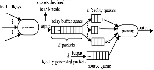
As illustrated in Fig. 1, each node in the MANET maintains n − 1 individual queues, one source queue for storing the packets that are locally generated at this node, and n − 2 parallel relay queues for storing packets of other flows (one queue per flow). All these queues follow the FIFO (first-in-first-out) discipline. Similar to the available studies on buffer-limited wireless networks [9], [10], we consider the following practical buffer constraint that all the n − 2 relay queues of a node share a common relay buffer with the limited buffer size of B packets, while the buffer size of source queue is unlimited. We adopt this buffer constraint here mainly due to the following reasons. First, the mathematical tractability of this assumption allows us to gain important insights into the structure of E2E delay analysis. Second, the analysis under this assumption provides a meaningful theoretical result in the limit of infinite source
buffer. Third, in a practical wireless network, each node usually prefers to reserve a much larger buffer space for storing its own packets than that for storing packets of other flows.
Also, even in the case that the buffer space of source queue is not enough when bursty traffic comes, the congestion control in the upper layer can be executed to avoid the loss of locally generated packets [11].
C. HANDSHAKE-BASED 2HR SCHEME
Regarding the routing scheme, we focus on the 2HR scheme, because it is simple yet efficient and thus serves as a class of attractive routing protocols for MANETs [12], [13]. To avoid unnecessary packet loss and support the efficient operation of the concerned buffer-limited MANETs, we introduce a handshake mechanism with negligible overhead1 into the 2HR scheme such that the packet dropping will not happen even in the case of relay buffer overflow. Once a node (say S) gets access to the wireless channel in a time slot, it executes the new handshake-based 2HR (H2HR for short) routing scheme summarized in Algorithm 1.
Algorithm 1 H2HR algorithm
1: if The destination D is within the transmission range of S then 2: S executes Procedure 1.
3: else if There exist other nodes within the transmission range of S then 4: With equal probability, S selects one node as the receiver.
5: S executes Procedure 2 or Procedure 3 equally with the receiver. 6: end if
Procedure 1 Source-to-destination (S-D) transmission 1: if S has packets in its source queue then
2: S transmits the head-of-line (HoL) packet in its source queue to D. 3: S removes the HoL packet from its source queue.
4: S moves ahead the remaining packets in its source queue. 5: else
7: end if
Procedure 2 Source-to-relay (S-R) transmission 1: if S has packets in its source queue then
2: S initiates a handshake with the receiver to check whether the relay buffer of receiver is full or not. 3: if The relay buffer of receiver does not overflow then
4: The receiver dynamically allocates a new buffer space to the end of the corresponding relay queue. 5: S transmits the HoL packet in its source queue to the receiver.
6: S removes the HoL packet from its source queue. 7: S moves ahead the remaining packets in its source queue. 8: end if
9: else
10: S remains idle. 11: end if
Procedure 3 Relay-to-destination (R-D) transmission 1: if S has packets destined to the receiver then
2: S transmits the HoL packet in its corresponding relay queue to the receiver. 3: S removes the HoL packet from this relay queue.
4: S moves ahead the remaining packets in this relay queue.
5: This relay queue releases one buffer space to the common relay buffer of S. 6: else
7: S remains idle. 8: end if
D. DEFINITIONS
Here we introduce some important definitions involved in this study.
Relay-buffer Overflowing Probability (ROP): For the concerned MANET with a given packet generating rate λ in each node, the relay-buffer overflowing probability po(λ) of a node is defined as the probability that the relay buffer of this node overflows (i.e, the relay buffer is full).
Queuing Delay: The queuing delay is defined as the time it takes a packet to move to HoL in the source queue (i.e., the source node starts to deliver it) after it is generated by its source.
Delivery Delay: The delivery delay is defined as the time it takes a packet to reach its destination after its source starts to deliver it.
End-to-end Delay: The end-to-end delay is defined as the time it takes a packet to reach its destination after it is generated by its source, which is the sum of its queuing delay and delivery delay.
III. PLATFORM DESIGN
Fig.2 Architecture diagram of End-to-End delay
Each node in the MANET maintains n − 1 individual queues, one source queue for storing the packets that are locally generated at this node, and n − 2 parallel relay queues for storing packets of other flows. All these queues follow the FIFO discipline. Similar to the available studies on buffer-limited wireless networks, we consider the following practical buffer constraint that all the n − 2 relay queues of a node share a common relay buffer with the limited buffer size of B packets, while the buffer size of source queue is unlimited. We adopt this buffer constraint here mainly due to the following reasons. First, the mathematical tractability of this assumption allows us to gain important insights into the structure of E2E delay analysis. Second, the analysis under this assumption provides a meaningful theoretical result in the limit of infinite source buffer. Third, in a practical wireless network, each node usually prefers to reserve a much larger buffer space for storing its own packets than that for storing packets of other flows. Also, even in the case that the buffer space of source queue is not enough when bursty traffic comes, the congestion control in the upper layer can be executed to avoid the loss of locally generated packets.
A. HANDSHAKE-BASED 2HR SCHEME
The 2HR scheme is simple but efficient and thus serves as a class of attractive routing protocols for MANETs. To avoid unnecessary packet loss and support the efficient operation of the concerned buffer-limited MANETs, we introduce a handshake mechanism with negligible overhead into the 2HR scheme such that the packet dropping will not happen even in the case of relay buffer overflow.
B. NETWORK CREATION AND TOPOLOGY FORMATION
In NS2, the CMU extension is presented with some wireless supports for simulating multi-hop wireless networks complete with physical, data link and MAC layer models on NS-2. The Distributed Coordination Function (DCF) of IEEE 802.11 for wireless LANs is adopted as the MAC layer protocol. Each channel bandwidth is 2Mb/s. The Two-Ray Ground Reflection Approximation is used as the radio propagation model with a constant transmission range of 250 meters. The send buffers of both protocols maintain 64 packets. The buffer stores all data packets which are waiting for a route. To prevent buffering of packets indefinitely, packets are dropped if they wait in the send buffer for more than 30 sec. Both data and routing packets sent by the routing layer are queued in the interface queue until the MAC layer can transmit them. The interface queue is FIFO, with a maximum size of 64. Routing packets has higher priority than data packets in the interface queue. Our simulation modeled a network of 50 mobile nodes (MNs), moving according to a Random Waypoint Model (RWM), in a bounded area of size 1500 meter×900 meter. Traffic and mobility models are used to evaluate the performance, respectively.
The mobility model uses the RWM in a rectangular field. Here, each node starts its journey from a random location to a random destination with a randomly chosen speed (uniformly distributed between 1–20 m/sec). Once the destination is reached, another random destination is targeted after a pause time. We generated various different pause times, which affect the relative speeds of the mobile nodes. In addition, we set pause time as zero for traffic load model. The sources of traffic model are CBR (continuous bit-rate). The source-destination pairs are spread randomly over the network. Only 512 byte data packets are used. The number of source-destination pairs and the packet sending rate in each pair is varied to change the offered load in the network. We use 10, 20, 30, 40 traffic sources and a packet rate of 4 packets/sec, especially in mobility model, the source-destination pairs are 20. The number of traffic flows varies over time to provide various load environments.
C. DATA TRANSMISSION WITHOUT RELAY
If the destination is within the transmission range of source then if source has packets in its source queue then it transmits the head-of-line (HoL) packet in its source queue to destination. Then source removes the HoL packet from its source queue.then source moves ahead the remaining packets in its source queue otherwise source remains idle.
D. DATA TRANSMISSION WITH RELAY
If source has packets in its source queue then source initiates a handshake with the receiver to check whether the relay buffer of receiver is full or not. if The relay buffer of receiver does not overflow then receiver dynamically allocates a new buffer space to the end of the corresponding relay queue. source transmits the HoL packet in its source queue to the receiver. Then source removes the HoL packet from its source queue.
IV. IMPLEMENTATION
Network simulator 2 is used as the simulation tool in this project. NS was chosen as the simulator partly because of the range of features it provides and partly because it has an open source code that can be modified and extended. There are different versions of NS and the latest version is ns-2.1b9a while ns-2.1b10 is under development
A. NETWORK SIMULATOR (NS)
Network simulator (NS) is an object–oriented, discrete event simulator for networking research. NS provides substantial support for simulation of TCP, routing and multicast protocols over wired and wireless networks. The simulator is a result of an ongoing effort of research and developed. Even though there is a considerable confidence in NS, it is not a polished product yet and bugs are being discovered and corrected continuously.
NS is written in C++, with an OTcl1 interpreter as a command and configuration interface. The C++ part, which is fast to run but slower to change, is used for detailed protocol implementation. The OTcl part, on the other hand, which runs much slower but can be changed very fast quickly, is used for simulation configuration. One of the advantages of this split-language program approach is that it allows for fast generation of large scenarios. To simply use the simulator, it is sufficient to know OTcl. On the other hand, one disadvantage is that modifying and extending the simulator requires programming and debugging in both languages.
1. Topology: Wired, wireless
2. Scheduling Algorithms: RED, Drop Tail, 3. Transport Protocols: TCP, UDP
4. Routing: Static and dynamic routing
5. Application: FTP, HTTP, Telnet, Traffic generators
B. ARCHITECTURE OF NS-2
Fig.4 Architecture of NS-2
C. SIMULATION RESULTS
In this section, we first conduct simulations to validate our theoretical framework for the E2E delay modeling in buffer limited MANETs, then provide discussions about the impacts of network parameters on delay performance.
Fig.5 End-to-end delay vs. packet generating rate λ under different settings of relay buffer size. n = 32,m = 4.
Fig.5 shows the relationship between the expected E2E delay E{T } and packet generating rate λ .We can see that under buffer-limited scenarios, as λ increases, E{T } doesn’t increase all the time because the delivery delay will decrease when λ exceeds a specific value, however when λ approaches the corresponding throughput capacity, E{T } increases sharply because the queuing delay tends to infinity. It also can be seen that when λ is small, E{T } under B = 5 is smaller than that under B = 20, since both of the queuing delay under two settings are small, but a small relay buffer can lead to a small delivery delay.
Fig.6 End-to-end delay vs. relay buffer size.
n = 32,m = 4.
We illustrate in Fig. 6 how E{T } varies B under the settings of (n = 32,m = 4, λ = {0.01, 0.02}). According to known formula , μ = 0.0227 when B = 1, and μ increases as B increases.
Thus, for λ = 0.01 which is much smaller than 0.0227, E{T } increases as B increases and finally tends to a constant 206.92 which can be determined by known formula. While for λ = 0.02 which is very close to the μ under B = 1, E{T } under B = 1 is very large. With B increasing, the corresponding μ increases, leading to the E{T } first decreases, then increases and finally tends to a constant 221.65.
B = 5.
We further illustrate in two 3D figures (Fig. 7 and Fig. 8)that how E{T } is influenced by {n, λ} and {n, B}, respectively (the ratio of n to the number of cells keeps as 2). We can see that the variations of E{T } with n are complicated, but in general E{T } increases as n increases. A more careful observation is that when n increases, E{T } first increases almost linearly when λ is much smaller than μ, then increases quickly when λ approaches μ. For example, these behaviors can be found in Fig. 14 under λ = 0.23 and in Fig. 8 under B = 1.
V. CONCLUSION
This paper represents a significant step towards the exact end-to-end delay modeling of practical buffer-limited MANETs. With the help of the theories of Fixed-Point, QBD process, EMC and AMC, a novel theoretical framework has been developed to efficiently depict the highly dynamics in such networks. This framework is general in the sense that it can be applied to the MANETs with any mobility model that leads to the uniform distribution of the locations of nodes, and anyMAC protocol as long as the probabilities psd , psr and prd there can be determined. Also, it is expected the framework can shed light on the E2E delay modeling for multi-hop MANETs. Extensive simulations have been conducted to validate the efficiency and applicability of our framework, and some interesting theoretical findings about the impacts of network parameters on delay performance have been discussed.
Our E2E delay modeling for buffer-limited MANETs is based on the 2HR routing and relay buffer constraint, so one of the future research directions is to extend our study to the E2E delay modeling for MANETs with multi-hop routing schemes and more practical buffer constraint on both source buffer and relay buffer. Another appealing direction is to explore the delay modeling for the concerned MANETs with the consideration of more practical network settings (such as the wireless channel fading) and apply the well-known NS-2 network simulator for model validation.
REFERENCES
[1] C.R.Lin and J.S. Liu., “QoS routing in ad hoc wireless networks”, IEEE J.Select.Areas Commun., vol.17, pp.1488-1505, 1999. [2] C.Perkins, “Ad-hoc On-Demand Distance Vector (AODV) routing”, RFC3561[S], 2003.
[3] D.B.Johnson, D.A.Maltz, Y.C.Hu, “The Dynamic Source Routing protocol for mobile ad hoc networks”, Internet Draft, 2004.
[4] J.Hong, “Efficient on-demand routing for mobile ad hoc wireless access networks”, IEEE journal on selected Areas in Communications 22(2004), 11-35.
[5] Luo Junhai, Xue Lie and Ye Danxia “Research on multicast routing protocols for mobile ad hoc networks” Computer Networks52(2008), 988-997.
[6] M. J. Neely and E. Modiano, “Capacity and delay tradeoffs for ad-hoc mobile networks,” IEEE Trans. Inf. Theory, vol. 51, no. 6, pp. 1917–1936, Jun. 2005.
[7] M. Grossglauser and D. Tse, “Mobility increases the capacity of ad hoc wireless networks,” IEEE/ACM Trans. Netw., vol. 10, no. 4, pp. 477– 486, Aug. 2002.
[9] L. B. Le, E. Modiano, and N. B. Shroff, “Optimal control of wireless networks with finite buffers,” IEEE/ACM Trans. Netw., vol. 20, no. 4, pp. 1316–1329, Aug. 2012.
[10] J. D. Herdtner and E. K. Chong, “Throughput-storage tradeoff in ad hoc networks,” in Proc. IEEE INFOCOM, 2005, pp. 2536–2542.
[11] A. E. Gamal, J. Mammen, B. Prabhakar, and D. Shah, “Optimal throughput-delay scaling in wireless networks–Part I: The fluid model,” IEEE Trans. Inf. Theory, vol. 52, no. 6, pp. 2568–2592, Jun. 2006.
[12] L. Hanzo and R. Tafazolli, “A survey of qos routing solutions for mobile ad hoc networks,” IEEE Commun. Surveys Tuts., vol. 9, no. 2, pp. 50– 70, Second Quarter 2007.