A Study to Optimize Process Parameters of
FSW Joints by Using Design-Expert and
Fuzzy-Approach
Y. Sankara1, J. Venumurali2, *, G. Sivaramudu 1, K. Saraswathi 1
Lecturer, Department of Mechanical Engineering, G. M. R.Polytechnic College, Srisailam, AP, India1 Research Scholar, Department of Mechanical Engineering, S. V. University, Tirupati, AP, India2
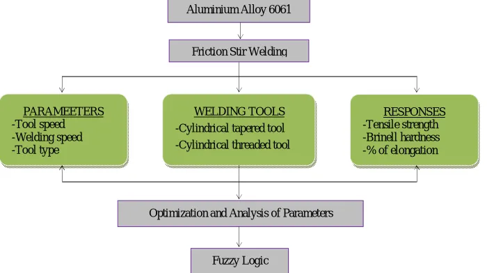
ABSTRACT: Friction stir welding (FWS) is one of the most vital joining processes in the present scenario. In case, where find its use in structures used by wrought or extruded aluminium which seeks very high strength. It uses a non- consumable tool to adhere two faces without melting base material. In this study aluminium alloy AA6061 joints are welded successfully by friction stir welding process using five rotational speeds, three weld speeds and two different pin profiles. The effects of welding speed, tool rotation and tool profile on the weld performance of joints are investigated by conducting tensile test, hardness test and calculating percentage elongation. Maximum tensile strength 119.781 MPa was exhibited by the FSW with optimized parameters of 950 rpm as tool speed (TS), 25 mm/min as welding speed (WS) using cylindrical tapered tool. Minimum percentage elongation 5.975 is exhibited by the FSW with the optimized parameters of 900 rpm as TS, 15 mm/min as WS using cylindrical threaded tool. Maximum Brinell hardness number 72.122 is exhibited by the FSW joint fabricated with the optimized parameters of 850 rpm as TS, 15 mm/min as WS using cylindrical tapered tool. The fuzzy input membership functions and the output membership functions assigned based upon the experimental condition. All membership conditions (both inputs and output for model) are in triangle and well distributed.
KEYWORDS: AA6061 aluminium alloy, FSW, Tool Speed, Welding Speed, Tensile strength, % of elongation, Brinell hardness number.
I.INTRODUCTION
Friction stir welding (FSW) is a relatively new joining process that is presently attracting significant attention. FSW is a solid state welding process where a machine rotates, plunges, and then traverses a distinct shaped FSW tool along a joint to form a weld. Deep research was carried out on FSW in the last decade to join several non-ferrous and ferrous materials and achieved many useful out comes [1]. The process has capable application for lower melting alloys, which are very much critical to be joined by traditional fusion welding [2].
Several cast and wrought aluminium alloys are used in aircraft structures, automobile bodies, missile components and military tanks reported by [3]. the effect of tool rotational and traversing speed on microstructure and tensile strength of dissimilar friction stir welded A356 and AA6061-T6 joints were s studied [4]. The traverse motion of the tool was resulted in the transportation of plasticized material from front to back of the tool. The axial force applied with respect to the tool axis forges the plasticized material to complete the joining process explored by [5,6].
The RSM is very useful in enhancing a suitable imprecise structure for the sound-designed relationship between the independent variables and response variables that may demonstrate the characteristics of FSW joints [7]. Also Fuzzy-logic-based multi-criteria decision making approaches also become very popular in optimization of manufacturing processes reported by Satpathy et al., [8].
Aluminium Alloy 6061
Friction Stir Welding
Optimization and Analysis of Parameters WELDING TOOLS
-Cylindrical tapered tool -Cylindrical threaded tool
RESPONSES -Tensile strength -Brinell hardness -% of elongation PARAMEETERS
-Tool speed -Welding speed -Tool type
Fuzzy Logic
alloy, which have been established using response surface methodology.Empirical relationship between FSW parameters and tensile strength was constructed based upon the experimental data and obtained by six parameters-five levels central composite design has been proposed [10].Ultimate tensile strength (UTS) of the joints fabricated by FSW has been predicted via mathematical relation with the help of response surface methodology (RSM), also the influence of process parameters on the weld strength of AA3003 joints investigated by Amit goyal et al., [11]. Karthikeyan and Balasubramanian [12] reported that the Response surface methodology (RSM) was applied to optimize the Friction stir spot welding (FSSW) parameters to attain maximum lap shear strength of the spot weld.
In this work an attempt is made to join 6 mm thickness casted AA6061 alloy using FSW with tool material as HSS (High speed steel) with two varieties such as, (i). Cylindrical Tapered grooved Tool, (ii). Threaded cylindrical pin profiled tool. Further investigation made on to measure tensile strength and brinell hardness number of the welded one. Moreover optimization of process parameters was carried using DOE with input parameters as tool speed, welding speed and tool type, and the output responses as tensile strength, percentage of elongation and Brinells Hardness Number. Finally developed a design matrix for the same and the variations are described using graphical media.
II.EXPERIMENTALWORK
The rolled plates of 6 mm thickness of AA6061 aluminum alloy has cut into required size of 200 mm x 75 mm x 6 mm by using milling machine. The chemical composition of Al-6061 alloy has described in Table 1.
Before conducting actual FSW process, a large number of trail runs have to be carried out, in order to make conformation to yield the good feasible results in this process. This is the toughest and more sensitive task to be prepared. Later it is need to concentrate on optimization techniques to find out feasible results in this concern. For this, first choose the following process parameters.
Welding feed: 15 mm/min, 25 mm/min and 35 mm/min.
Rotational speed : 800rpm, 850rpm, 900rpm, 950rpm and 1000rpm.
Tool type: tool 1(Cylindrical Tapered grooved Tool), tool 2 (Threaded cylindrical pin profiled tool).Fig. 1 The over view of an Experimental Process. Table.1 Chemical composition of Aluminium 6061 alloy
Element Si Fe Cu Mn Mg Cr Aluminium
FSW has carried out with great care in the well-defined environment in order to achieve a sound joining of between Aluminium 6061 alloys. The over view of the entire process has been shown in Fig. 1.
2.1 Tensile strength
After performing the FSW, the specimens were prepared to conduct tensile tests to observe tensile behaviour of the welded specimens. Tensile tests carried out on universal testing machine (UTM) of following specifications furnished in Table 2.
Table.2 Specification of Universal testing machine
Machine Computerized Universal Testing Machine
Make Rockwell Testing Aids
Modal TUE-C400
Measuring Capacity 400 KN
Measuring range 0-40 KN
Resolution of piston movement 0.01MM
Tensile test specimens are prepared as per ASTM E8 standard and transverse tensile properties such as tensile strength, percentage of elongation and joint efficiency of the FS welded joints are evaluated using computerized UTM. For each welded plate, two specimens are prepared and conducted tensile test.
Percent of elongation is determined by fitting together, after fracture, the parts of the specimen and measuring the distance between the original gauge marks and obtained by
Elongation (percent)= ×100 ……….eqn. (1)
Lf and L0 are final and original gauge lengths respectively. In reporting percent elongation, the original gauge length has to be specified.
2.2 Hardness test
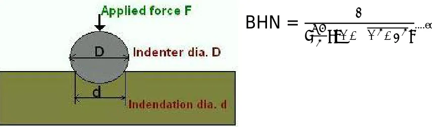
The hardness was measured by using Brinell hardness tester, which is usually consists of a hand operated vertical hydraulic press, designed to force a ball indenter. In this experiment, the material test with a ball of 10 mm diameter made of hardened steel under a load of 500 kg to avoid excessive indentation in case of nonferrous (here Aluminum) materials. The full load is normally applied for dwelling time of 30 seconds in this case. The diameter of the indentation left in the test material is measured with a low powered microscope. The Brinell harness number is calculated by using this formula.
BHN =
√
....eqn. (2)2.3 Optimization
Efficient optimization leads to the improved process control, which results in one or more of the following benefits: i). Lower product variation, ii). Higher value products iii). Increase throughput, iv). Reduce utility usage, and v). Improve safety. Because these benefits are economically significant, the use of advanced process control is essential to companies engaged in competitive markets.
2.3.1 Design of Experiments
Designed Experiments are also powerful tools to achieve manufacturing cost savings by minimizing process variation and reducing rework, scrap, and the need for inspection. There are three aspects of the process that are analyzed by a designed experiment:
Factors or inputs can be classified as either controllable or uncontrollable variables. Controllable variables concern of material, such as tools, sequence of operations, skinless of technicians etc., involved. Uncontrollable variables as which causes variability under normal conditions, but they can control during the experiment by using blocking and randomization.
Levels or settings of each factor. Examples include the type of tool profile, welding speed, tool rotation speed etc.
Response or output of the experiment. In the case of Friction Stir Welding (FSW), tensile strength, % elongation, BHN etc are measurable outcomes potentially influenced by the factors and their respective levels.
Developing Mathematical Models for the process parameters
In applying the responsesurface methodology, the independent variable was viewed as a surface to which a mathematical model is fitted. The second order polynomial (regression) equation used to represent the response surface Y is given by,
Y=b0+b1X1+b2X2+b3X3+---+bkXk………..eqn. (3)
In order to estimate the regression coefficients, a number of experimental design techniques are available. Using these normal equations solved the coefficients of regression model and then fitted regression line for a model.
nb0 + b1∑ + b2∑ =∑ ………..eqn. (4)
b0X1 + b1∑ + + b2∑ =∑ X1………..eqn. (5)
b0X2 + b1∑ + + b2∑ + X2………..eqn. (6)
2.3.2 Fuzzy Model
Fuzzy Logic is a multi-valued logic that allows intermediate values to be defined between conventional evaluations like true/false, yes/no, high/low, etc. Notions like rather tall or very fast can be formulated mathematically and processed by computers.
This investigation deals with stir welding. These experimental studies are carried out to investigate the intrinsic relationship between response surface method and operational conditions in AA6061 process on stir welding by using tool type. A set of cutting tests are performed under different operational conditions and measure output parameter after each tool. Experiments were conducted to study the tensile strength, percentage elongation and Hardness number.
III. RESULTS AND DISCUSSIONS
In Design Expert software, a mathematical model for the responses i.e., for output parameters (tensile strength, %elongation, Brinnel hardness number) was developed with the help of input parameters (tool speed, welding speed and tool type). For each respon se a mathematical equation in terms of input parameters was developed through which the unknown response can be obtained by substituting the input parameters. The values which are obtained from mathematical equations are called as Predicted values.
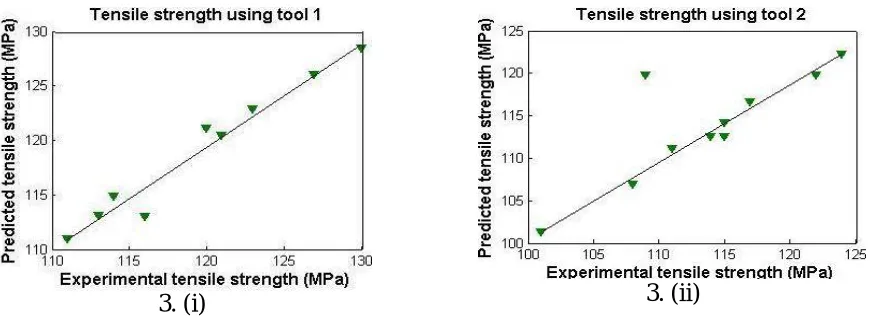
The relationships between actual and predicted responses (Correlational graphs for FSW AA 6061 Aluminium alloy) are depicted in Fig. 3(i)-(vi). The observed responses (tensile strength, percent of elongation and hardness) of FSW AA6061 alloys compared with the predicted responses achieved from the model and their respective regression scatter charts by using tool 1 and tool 2 respectively are presented inFig. 3.
3. (i)
3. (ii)
The corresponding tensile strength in Fig. 3(i) presents the normal probability of scatter chart, depicts the residuals decline on a straight line representing the normally distributed errors for the developed model. The plot as shown in Fig. 3(ii)which caused by the tool 2 exhibits nearly similar to that of Fig. 3(i). Here there is no too very differences observed.
3. (iii)
3. (iv)
In the case of percent of elongation obtained in with respect of tool 1 and tool 2 showed in Fig. 3(iii) and Fig. 3(iv). Both are standing in the abnormal phenomena because of the internal structure changes in the material due to FSW.
3. (v)
3. (vi)
In Fig. 4(a) and (c) were representing the ribbon contours of tensile strength and percent of elongation which are relatively sensitive to changes in rotational speeds than welding speeds, axial force. Where as in case of Fig. 4(e) representing hardness, it shows like grain contour which suggests independent of factor. Fig. 4(b), (d), and (f) presents three dimensional response surface plots for the tensile strength, percent of elongation and hardness respectively. The interaction effect axial force and welding speed has more significance than the interaction effect between welding and rotational speeds. Increase in rotational speed resulted in decrease in the initial force with increasing time [13]. The height from the surface A and B in every figure represents the tensile strength, percent of elongation and hardness of particular level of each tool speed and weld speed.At the highest axial force, the plunge depth produced by the tool into the work pieces is very much higher, which results in lower tensile strength of the joint [14]Hence, by collecting all the points of all the levels of tool speed and weld speeds, a surface is generated and the height of surface AB represents the Tensile Strength, percent of elongation and hardness for its corresponding inputs.
Fig. 4. (c), (d) Contour and Response plots for % elongation of AA 6061 Aluminium Alloy
Fig. 4. (e), (f) Contour and Response plots for hardness of AA 6061 Aluminium Alloy
IV. CONCLUSION
A study of process parameters of FSW joints optimized by using design-expert and fuzzy-approach have been studied and modelled to develop predicted tensile strength, %elongation and the Hardness number of friction stir welded AA6061 aluminiumalloy and important conclusions were drawn:
Rotational speed of the tool is the factor that has greater influence on tensile strength, followed by welding speed.
A maximum tensile strength of 119.781MPa is exhibited by the FSW joints fabricated with the optimized parameters of 950 rpm rotational speed, 25mm/min welding speed using tool 2.
Using fuzzy nature, tool type of the system is modelled. The fuzzy input membership functions and the output membership functions assigned based upon the experimental condition. All membership conditions (both inputs and output for model) are in triangle and well distributed.
The graphs which are obtained from the Design Expert Software are used to analyse the effect of one parameter on other by using the contour graphs.
V. FUTURE SCOPE OF THE PROJECT
Two kinds of tools tapered cylindrical (Tool 1) and threaded cylindrical (Tool 2) were applied here. It can be extend by using straight cylindrical, triangular and square tools. Box-behnken design, one factor method, central composite design can also be used in place of response surface methodology. ANOVA, Taguchi method can use for comparisons instead of RSM.
REFERENCES
[1] R. Nandan, T. Debroy, H. K. D. H. Bhadeshia, Recentadvances in frictionstirwelding —process, weldment structure and properties, Progress in Materials Science 53(6), pp.980–1023, 2008.
[2] Zhang D, Suzuki M, Maruyama K. Microstructural evolution of a heat-resistant magnesium alloy due to friction stir welding. Scripta Mater Vol. 52, pp.899–903, 2005.
[3] L. Karthikeyan, V. S. Senthilkumar, K. A. Padmanabhan, On the role of process variables in the friction stir processing of cast aluminum A319 alloy, Materials and Design 31 (2), pp.761–771, 2010.
[4] M. Ghosh, K. Kumar, S.V. Kailas, A.K. Ray, Optimization of friction stir welding parameters for dissimilar aluminum alloys, Materials and Design 31 (6),pp.3033–3037, 2010.
[5] R.S. Mishra, Z.Y. Ma, Friction stir welding and processing, Materials Science and Engineering R: Reports 50 (1–2),pp.1–78, 2005.
[6] P.L. Threadgill, A.J. Leonard, H.R. Shercliff, P.J. Withers, Friction stir welding of aluminium alloys, International Materials Reviews 54 (2), pp.49–93, 2009.
[7] GRUM J, SLABE J M. The use of factorial design and response surface methodology for fast determination of optimal heat treatment conditions of different Ni-Co-Mo surfaced layers [J]. Journal of Materials Processing Technology, 155(30),pp.2026−2032, 2004.
[8] Satpathy, Mantra Prasad, et al. "Modeling and optimization of ultrasonic metal welding on dissimilar sheets using fuzzy based genetic algorithm approach." Engineering Science and Technology, an International Journal18.4,pp.634-647, 2015.
[9] Palanivel, R., and P. Koshy Mathews. "Prediction and optimization of process parameter of friction stir welded AA5083-H111 aluminum alloy using response surface methodology." journal of Central South university 19.1, pp.1-8, 2012.
[10] Rajakumar, S., C. Muralidharan, and V. Balasubramanian. "Optimisation and sensitivity analysis of friction stir welding process and tool parameters for joining AA1100 aluminium alloy." International Journal of Microstructure and Materials Properties 6.1-2, pp.132-156, 2011. [11] Amit Goyal et al., "Optimization of Friction Stir Welding Parameters for AA3003 Aluminum Alloy Joints Using Response Surface
Methodology."International Journal of Mechanics and Solids Vol. 9.1,pp.15-26, 2017.
[12] Karthikeyan, R., and V. Balasubramanian. "Predictions of the optimized friction stir spot welding process parameters for joining AA2024 aluminum alloy using RSM." The International Journal of Advanced Manufacturing Technology 51.1,pp.173-183, 2010.
[13] Ouyang JH, Jandric D, Kovacevic R, Song M, Valantm M. Visualization of material flow during friction stir welding (FSW) of the same and dissimilar aluminium alloys. In: Proceeding of 6th trends in weld research, pp.229–40, 2002.