† Corresponding author
DOI: 10.18488/journal.2/2015.5.1/2.1.31.37 ISSN(e): 2223-1331/ISSN(p): 2226-5724
© 2015 AESS Publications. All Rights Reserved. 31
EXPERIMNENTAL METHOD TO MEASURE THE MECHANIC BEHAVIOR OF
COMPRESSED EARTH BLOCKS IN CONTINUOUS COMPRESSION
BOUFFOUE Moro Olivier
1--- KOUAKOU Conand Honoré
2†--- KOUADIO Koffi
Clément
3--- ASSANDE Aka Alexandre
4--- OUATTARA Souleymane
5---
EMERUWA Edjikémé
61,2,3,4,5,6 Laboratoire de Géomatériaux (UFR), Sciences de la Terre et des Ressources Minières (STRM), Université Félix
HouphouetBoigny, Côte d’Ivoire
ABSTRACT
This article presents the results of an experiment carried out in laboratory which aims at finding an
experimental method to determine the mechanic behavior of compressed earth blocks through a
very simple compressive test. As a matter of fact, the evaluation of the deformation of blocks under
a progressively increasing load, by the means of a load cell and the Linear Variable Displacement
Transducer (LVDT) put together on a manually operated press, has indeed enabled us to realize a
strain-stress curve. Here, the analysis of this curve shows that the mechanic behavior of the earth
blocks in compression is pseudo-elastic and ends off by a macro-brittle rupture because the stress
is homogeneously distributed all over the surface of blocks. Therefore, we can use this device to draw up the behavior’s law of compressed earth blocks.
© 2015 AESS Publications. All Rights Reserved.
Keywords:
Compressive behavior, Pseudo-elastic modulus, Experimental device, Macro-brittle, Compressed earth.Contribution/ Originality
This work provides a new experimental methodology for the measurement of the behavior of
mechanic items under ordinary compression using a simple device easy to handle. This is to make
ways of featuring out the mechanic behavior of earth blocks formerly limited to found out the stress
resistance only.
1. INTRODUCTION
Nowadays, many people are taking great interest in earth masonry for its ecological properties
and high thermal inertia [1]. However, the use of compressed earth blocks for building should
compulsorily be in accordance with the standard technical specifications: to have good compressive
Journal of Asian Scientific Research
ISSN(e): 2223-1331/ISSN(p): 2226-5724
© 2015 AESS Publications. All Rights Reserved
32 strength properties. In that view, many studies carried out about earth blocks have been limited to
suggest methods to determine that resistance, according to the properties of the earth such as:
- the anisotropy related to blocks making;
- the faces deformation due to their dry shrinkage;
- the unsuitability of the dimensions of earth blocks: these dimensions can be neither useful
to undertake a true compressive test nor to reproduce the same test [2-6].
On the other hand, there led studies to set up the conditions over the earth and the method to be
used when making blocks so as to get the highest resistance values in compression [4, 5, 7-9].
The aim of these specifications is to predict the behavior of earth block masonries. This is not
a mere way to determine or to improve some technical performances. Indeed, it is to establish a
definite computer code for earth masonries, like Euro code 6 did for fired earth blocs or concrete
blocks. To reach this goal, a campaign for the experimental determination of the mechanical
behavior of earth blocks under compressive load had been initiated [10-12]. But the device for that
experiment is too expensive, not every laboratory was able to realize those tests. That is the reason
why, only few results are available. So, this study has been undertaken, in order to develop
experimental process through a very simple compressive test, homogeneous and reproducible,
using a less expensive device.
2. MATERIAL AND METHODS
2.1. Material and ProcessFor this test, blocks are made by using:
- Clayey sand extracted from Cocody. The characteristics of the soil are presented in table
1.
- Cement CEM II/B 32.5.
- Water to the mixture at respectively 5 % and 13.5 % of moisture content.
A constant volume of the mixture is compacted with a static press (CINVA RAM type) which
develops a compaction pressure about 2 MN/m2. The nominal dimensions of the block are 300 mm
(length) x 140 mm (breadth) x 120 mm (height). Ten blocks are made and tested after 28 days of
drying.
Tableau-1. Characteristics of earth
Sand (10 mm – 0,080 mm) 70.7 %
Silt and clay (<0,080 mm) 29.3 %
Liquid Limit 41 %
Plastic Limit 21 %
Plasticity index 20 %
2.2. Arrangement of the Equipment
The device for the test consists of a hydraulic press with a capacity is of 5000 KN, a force
© 2015 AESS Publications. All Rights Reserved
33 The block is put between the ramp of the press, on a load cell with a capacity of 300 KN,
located under the inferior platen and the superior platen at the top. The constant piston
displacement rate of the inferior platen is of 0.25 mm/min. A lubricant is applied on the two
bearing surfaces of the trays, after each testing, in order to minimize the effects of the platens
restraint.
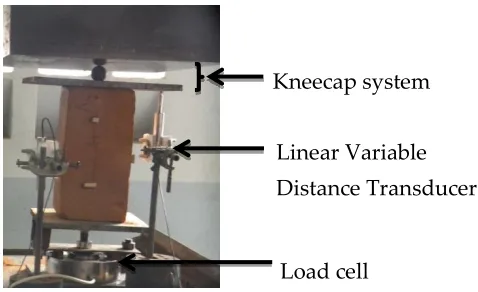
2.3.Instrumentation
Blocks are instrumented for the measurement of the axial displacements using the linear
variable displacement transducer (LVDT). The gauge lengths for the axial displacements are kept
at 5 mm. The LVDT and the load cell, as shown in figure1, are connected to a data acquisition
system by which the displacements and the weights of the loading are recorded and cached every
10 s.
2.4. Test Procedure
This test consists to follow the behavior of earth blocks under direct compression. The earth
block is put between the trays of the hydraulic press under the loading. Then, the loading is
progressively increased at a steady rate and made to move downward, according to the vertical
axis. Whenever the earth block receives weight from the loading, it undergoes changes in its
morphology. Here in this investigation, the specimens are compressed according to the NF P
18-406 standard. These are not tested in the direction in which they have been pressed, that is
according to the direction in which they are generally laid but, they are posed so that the length to
height ratio is 2 (fig. 1). And both the following compressive tests are performed:
- The direct compressive test: The procedure adopted in many national standards and codes of
practice is similar to that which is used for fired clay and concrete blocks. Here, the blocks are not
capped before but, they are put directly between the platens of the compressive device.
- The indirect compressive test: The procedure adopted is the same like in the direct compressive strength test. But in this case, the blocks aren’t directly put between the platens of the compressive device. A sheet of steel thick of 10 mm and a ball of steel are put between the surface of the block
and the superior tray. Most of the time, the surfaces of the block are not sufficiently flat and
parallel thence capping is necessary. Five (5) blocks are tested for each method. The data collected
are treated through calculation software like Excel. The strain ( ) and the stress ( ) are calculated
respectively from:
Where: l= the length of the block at time t (mm);
l0=the initial length of the block (mm); F= the weight of the loading (N); S= the area of the area of
© 2015 AESS Publications. All Rights Reserved
34 Figure-1. Experimental device
3. RESULTS AND DISCUSSION
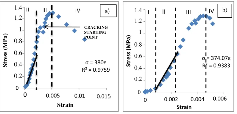
3.1. Earth Blocks BehaviorFigure 2 indicates a sample of the stress-strain curves of earth blocks in continuous
compression. The stress-strain is described by parabolic curves [10, 12]. We have found that it
exists a substantial non-linearity in the pre-peak range which also exists in the post-peak stage.
Nevertheless, the curves are similar to that of a cylindrical compressed earth block that has been
observed in laboratory tests.
A detailed study of Figure 2 reveals that the stress–strain curves can be divided into four parts. The first portions of the curves (the initial field) aren’t similar, which indicates that the platens do not perfectly adhere onto the surfaces of blocks because of their deformation. In the direct
compression test, this portion of the curve is more marked than in the indirect compression.
Consequently, the curves are not much affected when the ball system is used.
The second portions of the curves (the elastic field) are similar in both compression tests and
look like a line. However, a slight difference between the slopes of the stress–strain curves can be
observed. The strain is not much affected by the stress, if it is in the elastic field. The randomly
distributed micro-fractures have little influence on the blocks in this field.
But, when the stress becomes more important, about 75 to 85 % of the stress peak, the blocks
tend to deform in a non-uniform way. This is the third field or the plastic field. The Specimens
show a larger strain near the stress peak, which could be caused by the initial crack and its
propagation path.
The fourth portions of the curves (the post-rupture field) are located after the peak. Here, the
cracks are not stable but the breaking process becomes more stable. The blocks have a greater
residual strength and deformation capability that could be attributed to the rupture mode.
Kouakou and Morel [12] have shown, after several loads and unloads in the field of blocks elastic
behavior, that they have a permanent deformation and qualified this behavior as pseudo-elastic.
Load cell
© 2015 AESS Publications. All Rights Reserved
35 Figure-3. The stress-strain curve a) indirect compressive test b) direct compressive test
I= Initial field II=Elastic field III=Plastic field IV=Post-rupture field
3.1.Validation of the Test
Table 2 gives the results of the two tests. We can note that the ultimate stresses are similar for
both tests but the ultimate strain and the pseudo modulus are very different from one test to the
other. That could be explained by the confinement of blocks between the trays.
In fact, when the compressive stress increases, the specimen expands laterally, due to the
friction along the interface between the platen and the specimen. This is the reason why the
ultimate strain, in the direct compressive test, is more important while the pseudo modulus is less
important. But, as the sample aspect ratio is approximately equal to 2, the trays restraint effects on
the ultimate stress is reduced. According to P’kla, et al. [13], the confinement is responsible of the
overestimation of the compressive strength when the aspect ratio is less than 2. Thus, Krefeld [14]
and Heathcote and Jankulovski [15] suggested a factor to reduce the compressive strength.
Unfortunately, there was no factor to correct the deformation and the pseudo modulus. Otherwise,
the led experimentation was limited.
However, the pseudo elastic modulus determined by the indirect compressive test varies from
380 to 400 MPa. These values are similar to those obtained by P’Kla [10] confirming that the
results found in the indirect compression test are correct.
Now because of the dry shrinkage, the surface of the blocks is not very flat. So, when the
blocks are compressed, breaking appears in their angles, if the loading is not homogeneously
distributed on the blocks surface.
Moreover, with the ball system, the breaking arises from the center of the longitudinal face
(fig. 2). On the contrary, [16] has obtained a tilt crack due, not only to the shear in the isotope
material but also to the homogeneous distribution of the loading. Hakimi, et al. [11] have obtained
the same type of rupture as we did about earth blocks. They called it macro fragile rupture, due to
σ = 374.07ε R² = 0.9383
0 0.2 0.4 0.6 0.8 1 1.2 1.4
0 0.002 0.004 0.006
Str e ss (M Pa) Strain
IV
III
II
I
1.4 1.2 1 0.8 0.6 0.4 0.2 0.0040.002 0.006
b)
a)
σ = 380ε R² = 0.9759
0 0.2 0.4 0.6 0.8 1 1.2 1.4
0.0146 0.0196 0.0246 0.0296
Str ess ( M P a ) Strain
II III IV
0.005 0.01 0.01
5
© 2015 AESS Publications. All Rights Reserved
36 the homogeneous distribution of the load onto the blocks. That again confirms that the results
found with indirect compression are correct.
Table-2. Results of the compressive tests
Sample number
Direct compressive test Indirect compressive test
Ultimate stress (MPa)
Ultimate strain
Pseudo-elastic modulus (MPa)
Ultimate stress (MPa)
Ultimate strain
Pseudo-elastic modulus (MPa)
N°1 1.2 0.0047 374 1.3 0.005 380
N° 2 1 0.009 340 1.6 0.0044 395
N° 3 1.1 0.009 290 1.6 0.005 398
4. CONCLUSION
In this paper, we present the results of an experimental study over the influence of the two
compressive strength tests methodologies about the mechanic behavior of compressed earth blocks.
The main conclusions may be summarized as follows:
- In compressive, the compressed earth blocks have a non linear pseudo-elastic behavior which can be decomposed into three fields of behavior: elastic, plastic and post peak. To
these fields, we can add the initial stage behavior, due to the contact between the surfaces
of blocks and platens.
- The Stress-strain relationship is much affected by the testing procedure and the position of the sample. Therefore, when the experiment is correctly led, the loadings are applied
homogeneously onto the samples whence the aspects ratio equal to 2 macro fragile
ruptures has been adopted by earth blocks.
- The elastic modulus of the compressed earth blocks made with 5 % of cement ranges from 380 to 400 MPa, when blocks are put on their top.
The mechanic behavior of earth blocks can easily be determined experimentally with a
compressive machine, a load cell, a linear variable displacement transducer (LVDT) and a ball
system.
REFERENCES
[1] J. C. Morel, A. Mesbah, M. Oggero, and P. Walker, "Building houses with local materials: means
drastically reduce the environmental impact of construction," Building and Environment, vol. 36, pp. 1119-1126, 2001.
[2] A. Hakimi, A. Hamini, and H. Ouissin, "Rapport: Résultats d’essais de résistances mécaniques sur
échantillons de terre comprimée," Matériaux et Construction, vol. 29, pp. 600-608, 1996.
[3] J. C. Morel, A. P’Kla, and P. Walker, "Compressive strength testing of compressed earth blocks,"
Construction and Building Materials, vol. 21, pp. 303-309, 2007.
[4] M. Olivier, "Le matériau terre, compactage, comportement, application aux structures en blocs de
© 2015 AESS Publications. All Rights Reserved
37 [5] P. Walker, "Strength and durability testing on earth blocks," in Proceeding of the 6th International
Seminar on Structural Masonry for Developing Countries, Bangalore-India, 2000, pp. 110-118. [6] M. Olivier, A. Mesbah, Z. E1 Gharbi, and J. C. Morel, "Mode opératoire pour la réalisation d'essais
de résistance sur blocs de terre comprimée," Materials and Structures, vol. 30, pp. 515-517, 1997. [7] A. Mesbah, J. C. Morel, and M. Olivier, "Comportement des sols fins argileux pendant un essai de
compactage statique: Détermination des paramètres pertinents," Matériaux et Construction, vol. 32, pp. 687-694, 1999.
[8] K. C. Kouadio, "Elaboration et caractérisation de blocs d’argile stabilisée au ciment (Cimarg):
Influence de l’apport de dégraissant sur les caractéristiques physiques et mécaniques des blocs,"
Doctorat Sciences de la terre, Université de Cocody, Abidjan ; Côte d’Ivoire, 2010.
[9] C. H. Kouakou, "Valorisation des argiles de Côte d’Ivoire: Etude de la stabilisation de blocs d’argile
comprimée et stabilisée au ciment à l’aide de liants hydrauliques," Doctorat Sciences de la terre, Université de Cocody, Abidjan; Côte d’Ivoire, 2005.
[10] A. P’Kla, "Caractérisation en compression simple des blocs de terre comprimée (BTC): Application
aux maçonnéries: BTC- mortier de terre," Thèse de Doctorat de l’Institut National des Sciences
Appliquées de Lyon (France), 2002.
[11] A. Hakimi, O. Fassi-fehri, H. Bouabid, S. CharifD’ouazzane, and M. El Koribi, "Comportement
mécanique non linéaire du bloc de terre comprimée par couplage élasticité endommagement,"
Materials and Structure, vol. 32, pp. 539-545, 1999.
[12] C. H. Kouakou and J. C. Morel, "Strength and elasto-plastic properties of non-industrial building
materials manufactured with clay as a natural binder," Applied Clay Science, vol. 44, pp. 27-34, 2009.
[13] A. P’kla, A. Mesbah, V. Rigassi, and J. C. Morel, "Comparaison de méthodes d’essais de mesures
des caractéristiques mécaniques des mortiers de terre," Matériaux et Structures, vol. 36, pp. 108-117, 2003.
[14] W. J. Krefeld, "Effect of shape of specimen on the apparent compressive strength of brick masonry,"
in Proceeding of the American Society of Materials, Philadelphia, 1938, pp. 363-369.
[15] K. Heathcote and E. Jankulovski, "Aspect ratio correction factors for soil concrete blocks,"
Australian Civil Engineering transactions-Institution of Engineers Australia, vol. CE34, pp. 302-312, 1992.
[16] G. A. Azeredo, "Mise au point de procédure d’essais mécaniques sur mortiers de terre: Application à
l’étude de leur rhéologie," Thèse de Doctorat de l’Institut National des Sciences Appliquées de
Lyon, France, 2005.