IJEDR1302004 INTERNATIONAL JOURNAL OF ENGINEERING DEVELOPMENT AND RESEARCH | IJEDR Website: www.ijedr.org | Email ID: [email protected] 17
An Experimental Performance Study of Vortex Tube
Refrigeration System
Sankar Ram T.
Department Of Industrial Refrigeration and Cryogenics T. K. M. College of Engineering
Karicode, Kollam, Kerala [email protected]
Anish Raj K.
Department Of Mechanical Engineering Jyothi Engineering College Cheruthuruthy, Thrissur, Kerala [email protected]
Abstract— The phenomenon of temperature distribution in confined steady rotating gas flows is called Ranque-Hilsch effect. The simple counter-flow vortex tube consists of a long hollow cylinder with tangential nozzle at one end for injecting compressed air. The flow inside the vortex tube can be described as rotating air, which moves in a spring-shaped vortex track. The peripheral flow moves toward the hot end where a hot end plug is placed and the axial flow, which is forced back by the plug, moves in the opposite direction towards the cold end.
Keywords-Vortex tube; Refrigeration; cooling;
I. NOTATION
AC , AH : Areas of the cold orifice and at the hot end, respectively, mm2
AN , AT : Areas of the nozzle and the tube, respectively, mm2
DC , DN , DT : Diameters of the cold orifice, the nozzle and the tube, respectively, mm
L : Length of the tube, mm
mC , mH : Mass flow rates of cold and hot air, respectively, kg/s
mi : Mass flow rate of air at inlet nozzle, kg/s Ta : Ambient temperature, oC
TC , TH : Temperature of air at cold and hot ends, respectively, oC
To : Temperature of air inside the compressor tank, oC
vC , vH : Velocity of the air at cold orifice and at hot end, respectively, m/s
dTC : Temperature drop in vortex tube, oC
dia : Diameter
temp : Temperature
RHVT : Ranque-Hilsch Vortex Tube cold end: The end of RHVT were cold air is
produced
hot end : The end of RHVT were cold air is produced
SI units are used as far as possible and can be assumed wherever necessary if not otherwise mentioned.
II. INTRODUCTION
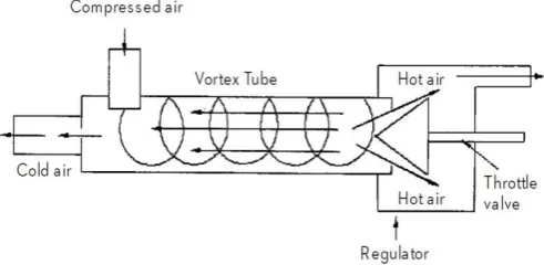
The vortex tube also known as Hilsch or Ranque tube1,2 is a simple device having no moving parts, which produces hot and cold air streams simultaneously at its two ends from a source of compressed air. It consists of a long tube having a tangential nozzle near one end and a conical valve at the other end, as shown schematically in Figure 1.
A diaphragm called cold orifice, with a suitable sized hole in its centre is placed immediately to the left of the tangential inlet nozzle. The compressed air is then introduced into the tube through this nozzle. The tangential flow imparts a whirling or vortex motion to the inlet air, which subsequently spirals down the tube to the right of the inlet nozzle. Conical valve at right end of the tube confines the exiting air to regions near the outer wall and restricts it to the central portion of the tube from making a direct exit. The central part of the air flows in reverse direction and makes exit from the left end of the tube with sizeable temperature drop, thus creating a cold stream. The outer part of the air near the wall of the tube escapes through the right end of the tube and is found to have temperature higher than that of inlet air.
Fig. 1 Schematic diagram of a vortex tube
Literature review reveals that there is no theory so perfect, which gives the satisfactory explanation of the vortex tube phenomenon as explained by various researchers6,9,10,11. Therefore, it was decided to carryout experimental investigations for understanding the heat transfer characteristics in a vortex tube. An attempt has been made to study the effect of various parameters like mass flow rates of cold and hot air, nozzle area of inlet compressed air, cold orifice area and hot end area of the tube. The study also investigates the effect of L/D ratio on the performance of the vortex tube.
III. DESIGN PROCEDURE
IJEDR1302004 INTERNATIONAL JOURNAL OF ENGINEERING DEVELOPMENT AND RESEARCH | IJEDR Website: www.ijedr.org | Email ID: [email protected] 18 nozzle diameter;
cold orifice diameter;
mass flow rates of cold and hot air; area at the hot end.
Fig. 2 Basic Design Outline Selected for construction
In the present investigation, a nozzle area to tube area ratio of 0.11 for maximum temperature drop has been considered, as suggested by Soni and Thomson7. Further, they suggested that the ratio of cold orifice area to tube area should be 0.080 for achieving maximum temperature drop. The same researchers also mentioned that the length of the vortex tube should be 45-55 times the tube diameter.
Keeping these suggestions in view, a vortex tube of size 18 mm inner diameter of CPVC was selected. The vortex tube was a 810 mm long pipe. Four straight nozzles were made and each had 2 mm diameter and was 2.5 mm long, long. Similarly, two cold orifices were used having hole diameters of 4.5 mm and 5.8 mm, respectively. A conical valve made of wood was provided on the right hand side of the tube to regulate the flow with diameters varying from 7 to 20 mm.
Materials were selected based on easy availability, ease of working, and insulating capability which is necessary for achieving the adiabatic conditions assumed. CPVC pipings are widely used in industries to carry hot fluid. The pipes used were rated for a maximum temperature of 80 oC.
Table 1 Design Parameters of equipment constructed Tube Inner
Diameter 18mm (d)
Cold Plate Orifice
Diameter 9mm (0.5d)
Inlet Nozzle
Diameter 2 mm (0.1d)
No. of Inlet
Nozzle 4
(depending on flow rate of air)
Length: Hot End 810mm (45d-55d)
Length: Cold End 20-30 mm (experimental value) Pressure Range 1 bar -6 bar (experimental value)
IV. EXPERIMENTAL SETUP
To study the effect of various parameters such as mass flow rates of cold and hot air, cold orifice area and hot end area on the performance of the vortex tube, an experimental set up was prepared as per design described earlier. The vortex tube components were made in a manner such that certain geometries of the tube could be changed from a maximum value to a minimum value.
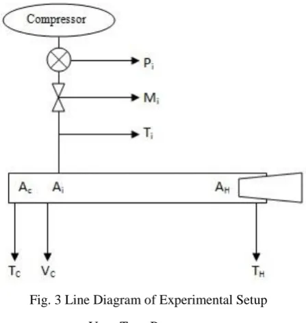
The line diagram of the experimental setup is shown in Figure 2. The temperature of air at cold and hot ends was measured with digital thermometers with an accuracy of ± 1 oC. The air velocities were measured by an anemometer. The pressures were measured by pressure gauges. All the instruments were calibrated before the measurements were actually observed/recorded.
Fig. 3 Line Diagram of Experimental Setup V. TEST PROCEDURE
The various parameters, which affect the performance of the vortex tube, were divided into following input and output variables:
Input variables: Area of cold orifice, Effective Area Of Hot End, Inlet Pressure, Inlet Mass Flow Rate
Output variables: Temperature of cold air, cold fraction, and Temperature of hot air.
The compressor was initially run for about 30 min to get a stable compressor air tank pressure. Firstly the cold end orifice was set to a value. For that value a pressure is set and the hot end valve is varied to get the output variables. The Pressure was varied to obtain various output variables. The procedure was repeated for various cold end orifice diameters. The values of density of air at both ends were calculated assuming the flow to be adiabatic.
The following assumptions were made for the ease calculation:
The entire system is insulated and the processes are adiabatic.
The outlet pressures are equal to atmospheric pressures5.
The cold end diaphragm and hot end conical valve does not absorb any heat.
There is no change in performance due to the projecting part of conical valve.
There is no effect of back pressure in the outlets.
VI. RESULTS
IJEDR1302004 INTERNATIONAL JOURNAL OF ENGINEERING DEVELOPMENT AND RESEARCH | IJEDR Website: www.ijedr.org | Email ID: [email protected] 19 results. The equipment designed was not for the best results ie.
least temperatures, but for more accurate results. The main problem observed was the heating up of the tubes due to friction during continuous use. To overcome this, the air flow was stopped in intervals and the equipment was allowed to cool down. Nevertheless the equipment worked as desired and the readings were obtained.
A. Effect Of Hot Plug Diameter
The effect of hot plug diameter was studied varying the effective plug diameter by moving the conical valve in and out of the tube.
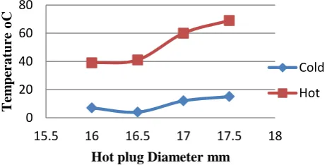
Figure 4 shows the effect of hot plug diameter on the output temperatures. The coldest temperatures were obtained at about 16.5 mm diameter of hot plug for a pipe of 18 mm internal diameter. Going higher than that value increases the temperature of cold air due to mixing of more hot air to the cold passage because of high pressure build up inside the pipe. Decreasing the plug diameter also increases the temperature due to reduce mass fraction of cold air. Reducing the diameter below a limit, it was observed that there is a negative pressure buildup near the nozzles leading to air suction at cold end rather than air rejection.
As the hot plug diameter increases, there was a small but steady rise in temperature at hot end. At very high plug diameters, above 17mm for an 18 mm pipe, there was a sudden increase of pressure leading to very high temperatures.
Fig. 4 Temperature vs Hot plug Diameter
Figure 5 shows the effect of hot plug diameters on the total temperature difference that can be obtained for different number of turns of the valve, which is an indication of total mass flow rate.
At very low hot plug diameters, there was no much appreciable temperature difference between the hot and cold outlet. As the diameter was increased there was a steady increase in temperature difference, which is a partial indication of efficiency of the unit.
Fig. 5 Temperature Difference At Outlet vs Hot Plug Diameter
B. Effect Of Mass Flow Rate
During the experiment, it was observed that the mass flow rate of air is the main characteristic feature that controls the temperature of cold air produced. Due to sudden expansion of air near outlet of nozzles, there is a low pressure region created just near the diaphragm placed. If the mass flow rate cannot supply enough amount of air there will be a negative pressure leading to suction of air through the cold outlet.
The mass flow rate is denoted for sake of simplicity in terms of number of turns of the ball valve used to control the mass flow rate. On a scale of 1 to 5 turns, the mass flow rate varies between 5.5 to 30 m3/s.
Figure 6 shows the effect of mass flow rate on hot outlet temperature. It can be seen that in all cases, as mass flow rate increases there is increase in temperature. At low hot plug opening, this rise is quite insignificant. But as the diameter of hot plug increases, the rise in temperature is quite dominant. Due to restrictions on material, the test for highest temperature was held at 80OC . It is also observed that at diameters less than 16.5 mm, There is no much effect by either hot plug diameter or mass flow rate.
Fig. 6 Hot End Temperature vs Mass Flow Rate (For Diffrent Hot Plug Openings)
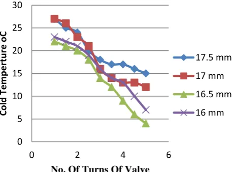
Figure 7 shows the effect of mass flow rate on cold outlet temperature. It can be seen that in all cases, as mass flow rate increases there is steady decrease in temperature at cold end. 0
20 40 60 80
15.5 16 16.5 17 17.5 18
T
em
pera
ture
o
C
Hot plug Diameter mm
Cold
Hot
0 10 20 30 40 50 60
15.5 16 16.5 17 17.5 18
Tem
p
Di
ff
o
C
Hot Plug Diameter mm
3
4
5
0 10 20 30 40 50 60 70 80
0 2 4 6
H
o
t
T
em
pera
ture
o
C
No. Of Turns Of Valve
17.5 mm
17 mm
16.5 mm
IJEDR1302004 INTERNATIONAL JOURNAL OF ENGINEERING DEVELOPMENT AND RESEARCH | IJEDR Website: www.ijedr.org | Email ID: [email protected] 20 Unlike the hot end temperature, the effect of mass flow rate is
quite predominant in case of cold end temperatures.
For increase in mass flow rate, there is continuous decrease of temperature, with no signs of a point of inflection. With high mass flow rates sub zero temperatures can be easily obtained in a vortex tube.
It is of quite importance that least temperatures are observed in hot plug diameter of 16.5 mm, going above or below these increases the cold end temperature.
Fig. 7 Cold End temperature vs Mass Flow Rate (For Diffrent Hot Plug Openings)
Figure 8 shows the effect of mass flow rate on temperaure diffrence that can be obtained on the vortex tube. It can be observed that a steady rise in temperaure diffrence is obtained sa mass flow rate is increased but as the hot plug diameter is reduced the rate of temperaure rise deceases. It is to be noted that at very low mass flow rates, the operation of vortex tube is hinged due to effect of back pressure at the cold exit.
Fig. 8 Temperature Difference vs Mass Flow Rate (For Diffrent Hot Plug Openings)
VII. CONCLUSIONS
1. The design of nozzle affects the conversion of pressure to velocity. It doesn't have much contribution in the energy separation process. The area of nozzle is a constant for given tube size and number of nozzles depends on mass flow rate possible.
2. Cold end temperature as well as adiabatic efficiency is more influenced by the mass flow rate and the size of the cold orifice rather than the size of the hot plug. 3. Higher temperature drops are obtained in vortex tube at
90% hot plug diameter and is due to higher hot temperatures rather that low cold temperatures.
4. The pressure and mass flow rate is to be kept at a range for proper operation of tube. The higher range is defined by the strength of tube while lower limit is defined by the tube diameter and hot plug diameter.
5. It is observed that maximum cooling effect is obtained at 16.5 mm of hot plug diameter, 90% of Tube inner diameter. CFD analysis shows an 86 % diameter gives maximum cooling effect9.
6. The material of tube has significant importance in design of vortex tube. The internal roughness increases friction, causing heating up of pipe and loss of tangential velocity of flow.
7. A 1- 5 O inclination of the inlet orifice towards hot end helped in reducing pressure buildup near the orifices, restricting further flow. A higher inclination increased the axial velocity, reducing the efficiency of operation.
ACKNOWLEDGMENT
The authors express their gratitude to staffs of Department of Mechanical Engineering and Department Of Applied Electronics, Jyothi Engineering College for providing necessary facilities and encouragement for the completion of this work. The authors also express their sincere thanks to the staff at production shop, and thermal laboratory for their continuous help in experimentation and preparation of this work.
REFERENCES
[1] G J Ranque. ‘Experiments on Expansion in a Vortex with Simultaneous Exhaust of Hot and Cold Air.’ Le Journal De Physique(Journal Of Physis), et le Radium (Paris), vol 4, June 1933, pp 1125-1130.
[2] R Hilsch. ‘The use of the Expansion of Aires in a Centrifugal Field as a Cooling Process.’ Review of Scientific Instruments, vol 13, February 1947, pp 108-113.
[3] U. Behera , P.J. Paul , S.Kasthurirengan , R. Karunanithi ,S.N. Ram, K. Dinesh, S. Jacob,2005, CFD analysis and experimental investigations towards optimizing the parameters of Ranque– Hilsch vortex tube, International Journal of Heat and Mass Transfer 48, 1961–1973
[4] Sachin U. Nimbalkar Michael R. Muller , An experimental investigation of the optimum geometry for the cold end orifice of a vortex tube, Applied thermal Engineering vol.29, 2008, p 509-51 .
[5] Bramo, A. R., et al.: Computational Fluid Dynamics Simulation Of Length To Diameter Ratio Effects On The Energy Separation In A Vortex Tube; Thermal Science, Year 2011, Vol. 15, No. 3, pp. 833-848
[6] R B Aronson. ‘The Vortex Tube: Cooling with Compressed Air.’ Journal of Machine Design, December 1976, pp 140-143. [7] Y Soni and W J Thomson. ‘Optimal Design of Ranque —
Hilsch Vortex Tube.’ ASME Journal of Heat Transfer, vol 94, no 2, May 1975, pp 316-317.
[8] R L Collins and R B Lovelace. ‘Experimental Study of Two Phase Propane Expanded through the Ranque — Hilsch Tube.’ ASME Journal of Heat Transfer, vol 101, no 2, May 1979, pp 300-305.
0 5 10 15 20 25 30
0 2 4 6
Co
ld
Te
m
p
e
rtu
re
o
C
No. Of Turns Of Valve
17.5 mm
17 mm
16.5 mm
16 mm
0 10 20 30 40 50 60
0 2 4 6
T
em
p
Dif
f
o
C
No. Of Turns Of Valve
17.5 mm
17 mm
16.5 mm
IJEDR1302004 INTERNATIONAL JOURNAL OF ENGINEERING DEVELOPMENT AND RESEARCH | IJEDR Website: www.ijedr.org | Email ID: [email protected] 21 [9] H Takahama and H Yokosawa. ‘Energy Separation in Vortex
with a Divergent Chamber.’ Transactions of ASME, vol 103, May 1981, pp 196-203.
[10] M Kurosaka. ‘Acoustic Streaming in Swirling Flow and the Ranque — Hilsch Effect.’ Journal of Fluid Mechanics, 1982, p 139.
[11] Y D Raiskii and L E Tankel. ‘Influence of Vortex Tube Configuration and Length on the Process of Energetic Air Separation.’ Journal of Engineering Physics, vol 27, no 6, December 1974, pp 1578-1581.