R E S E A R C H
Open Access
Iterative receivers with channel estimation for
multi-user MIMO-OFDM: complexity and
performance
Peter Hammarberg
*, Fredrik Rusek and Ove Edfors
Abstract
A family of iterative receivers is evaluated in terms of complexity and performance for the case of an uplink multi-user (MU) multiple-input multiple-output orthogonal frequency division multiplexing (MIMO-OFDM) system. The transmission over block fading channels is considered. The analyzed class of receivers is performing channel estimation inside the iterative detection loop, which has been shown to improve estimation performance. As part of our results we illustrate the ability of this type of receiver to reduce the required amount of pilot symbols. A remaining question to ask is which combinations of estimation and detection algorithms that provide the best trade-off between performance and complexity. We address this issue by considering MU detectors and channel estimators, with varying algorithm complexity. For MU detection, two algorithms based on parallel interference cancellation (PIC) are considered and compared with the optimal symbol-wise maximum a-posteriori probability (MAP) detector. For channel estimation, an algorithm performing joint minimum-mean-square-error (MMSE) estimation is considered along with a low complexity replica making use of a Krylov subspace method. An estimator based on the space alternating generalized expectation-maximization (SAGE) algorithm is also
considered. Our results show that low-complexity algorithms provide the best tradeoff, even though more receiver iterations are needed to reach a desired performance.
Keywords:MIMO, OFDM, multi-user detection, iterative receiver, complexity, channel estimation
1 Introduction
In future wireless systems high data rate transmissions need to be supported, requiring larger bandwidths to be used. At the same time, spectral efficiency is becoming increasingly important. A technology that has become popular in later years, and also found its way into many wireless standards such as, e.g., LTE [1], is the use of mul-tiple-input multiple-output (MIMO) antenna systems in combination with orthogonal frequency division multi-plexing (OFDM). OFDM is used to efficiently combat inter-symbol interference (ISI), inherent in broadband transmissions, while MIMO is used for improving the channel spectral efficiency and/or suppress interference.
Introducing multiple users (MU) into such systems, a MU-MIMO-OFDM system is created. In the uplink, accurate multi-user (MU) receivers are needed to harvest
the available gains. A significant number of algorithms, with varying complexity, have been proposed for this task; ranging from the simple zero-forcing detector to the high complexity maximum-likelihood (ML) detector. Please refer [2] for an overview.
The degree of channel state information (CSI) available at the receiver plays an important role in the design of the receiver structure. While it is convenient for theoretical investigations to assume that perfect CSI is available, prac-tical receivers need to obtain CSI via, e.g., noisy pilot sym-bol observations. In the case of a large coherence time, the accuracy of the channel estimate can be made high since many symbols can be dedicated for pilot information with-out any significant effect on the spectral efficiency. In fast fading environments, or packet-based systems, the number of pilot symbols must, however, be kept small to maintain a reasonable spectral efficiency. To this end, other more sophisticated transceiver structures have been developed [3-5]. These receivers jointly detect the data symbols and
* Correspondence: [email protected]
Dept. of Electrical and Information Technology LTH, Lund University, Box 118, SE-22100 Lund, Sweden
estimate the transmission channel, which allows for a lower number of inserted pilot symbols as compared to traditional pilot based transceiver systems. While the pro-spect of reducing the number of pilot symbols is impor-tant, these receivers are of limited utility since they have grossly larger computational complexity than traditional pilot based receivers. This complexity amplifies dramati-cally if the data is coded.
The discovery of the turbo principle [6] brought radical changes to the entire communication field. It is today understood that highly complex problems, such as jointly detecting coded data and estimating the underlying trans-mission channel, can be efficiently handled by iteratively solving much simpler sub-problems. In particular, during the last decade there has been a growing interest in itera-tively solving the joint coded data detection and channel estimation problem [7-10]. The receiver is alternating between decoding of the outer error correcting code, per-forming multi-user detection (MUD), and estimation the transmission channel, in an iterative manner. In [10], a the-oretical framework is presented for this, elsewhere ad-hoc, choice of receiver design; strengthening the motive for this choice.
Even though iterative algorithms can reduce the com-plexity of the digital receiver, they may still be of prohibi-tive complexity in many practical scenarios; representing itself in a large chip area and high power consumption. It is therefore important to find low-complexity algorithms that are both power efficient and can deliver performance required to reach high spectral efficiencies.
In the current literature, an impressive number of low-complexity algorithms have been proposed for the differ-ent compondiffer-ents of an iterative receiver, see e.g., [11]. However, few have studied the trade-off between complex-ity and performance for the entire receiver, including MUD, channel estimation and channel decoder. In [12], we have performed a trade-off analysis for an interleave division multiple access (IDMA) system, where a number of channel estimation algorithms are evaluated. One other exception is [13], where the complexity and performance of a set of receiver algorithms for MIMO multi-carrier code division multiple access (MC-CDMA) systems are investigated. In contrast to [13], this article evaluates a family of iterative receivers for an uplink MU MIMO-OFDM system, operating over block fading channels. Furthermore, we have tried to place a greater focus on the convergence properties of the different receiver configura-tions. The convergence speed is important since more iterations require a larger computational effort. Also worth mentioning is the work in [14], where a perfor-mance-complexity comparison of receivers for down-link MIMO-OFDM systems is performed. Unlike in our com-parison, the investigated receivers does not contain any channel estimator.
In our evaluation, the complexity of all the building blocks of the iterative receiver is derived, and related to the system performance. Our results show that low-complexity algorithms are generally sufficient, but more complex schemes may be needed if convergence speed, measured in iterations, is at focus. The main contribu-tions are summarized as follows
- A tradeoff analysis between complexity and perfor-mance is performed for a MU MIMO-OFDM system incorporating iterative channel estimation and MUD. Two popular channel estimation algorithms, one based on expectation maximization (EM) [15], and one performing a joint minimum-mean-square-error (MMSE) estimation of all user channels [8,9], are evaluated. A low-complexity approximation of the latter based on a Krylov subspace projection method, as presented in [13], is also evaluated. Three popular MUDs are considered; two parallel interference can-cellation (PIC) based detectors and one full maxi-mum a-posteriori probability (MAP) detector. The latter being a natural performance benchmark. - In the tradeoff analysis, the total complexity, in terms of complex multiplications, required to reach a given bit error rate (BER) is derived for all algo-rithm combinations at different signal-to-noise ratios and number of users. The results show that low-complexity schemes are generally providing the best tradeoff.
- The convergence properties of the different recei-ver combinations are presented, both in terms of BER, mean square estimation error, and through the use of extrinsic information transfer (EXIT) charts [16]. The EXIT charts visualize the exchange of extrinsic information between the outer code and the rest of the receiver incorporating channel esti-mation and MUD.
The rest of this article is organized as follows. In Sec-tion 2, a descripSec-tion of the considered MU-MIMO-OFDM system is given. The algorithms for obtaining the channel estimate are presented in Section 3, and the MUD algorithms in Section 4. In Section 5 the com-plexity of the algorithms is discussed, and in Section 6 the performance of different algorithm combinations is investigated. A complexity versus performance analysis is performed in Section 7, before the paper is summar-ized in Section 8.
2 System description
2.1 MU-MIMO-OFDM system overview
withNantennas. The users transmit blocks ofSOFDM symbols, each containing M sub-carriers. The firstSp
OFDM symbols are reserved for pilot symbols, which are known to the receiver. The following Sd= S –Sp
OFDM symbols contain coded data. The total number of information bearing signal constellation points per block, transmitted from each user, then becomes L=
SdM. A forward error correcting code (FEC) with rateR
is used to generate codewords, which after interleaving, are mapped onto the Lsignal constellation points. We restrict our investigations to the case of QPSK. An extension to other constellations is conceptually straightforward, but in general non-trivial [17]. After OFDM modulation and pilot insertion, the users trans-mit their signals over a frequency selective block fading channel, where the different multi-antenna links are independent and identically distributed (IID). The block fading assumption holds if the transmitted data blocks are much shorter than the channel coherence time. Thus, a system with short data blocks transmitted over a channel with moderate Doppler spread is considered. Furthermore, to allow for correct OFDM demodulation at the receiver, the users are assumed to be synchro-nized both in time and frequency. In frequency, the syn-chronization requirement is strict, but due to the use of a cyclic prefix (CP), the time requirement is somewhat relaxed to the case where the difference in arrival times is less than the duration of the CP minus the channel delay spread.
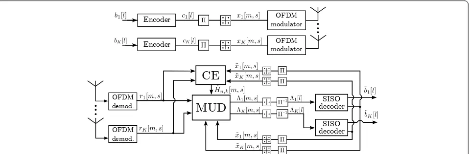
At the receiver, the signal is demodulated into the com-plex baseband, where an iterative receiver is implemented. The complexity-performance trade-off of this receiver is the focal point of this article. The receiver consists of three blocks; a channel estimator, a MUD, and a bank of soft-input-soft-output (SISO) channel decoders. First, an initial channel estimation is performed, based on the
transmitted pilot symbols. This estimate is then used in the MUD to separate the different user streams, which are then fed to the SISO decoders after de-interleaving (Π-1
). The output of the decoders are then used in the next itera-tion to update the channel estimate, and to further improve the user separation in the MUD. Multiple itera-tions are then performed in the same way. The different components are described in detail in later sections.
2.2 Input-output relationship of the channel
Next we turn the attention to a description of the input-output relationship of the channel used in this article. The notation introduced here will also be used for the description of the various algorithms. Furthermore, a low-rank description of the channel, being used by the channel estimation algorithms, is also introduced in section.
Under the assumption of block-fading channels, the discrete-time model for the received signal at the mth subcarrier, during the transmission of OFDM symbols, can be written as
r[m,s] =H[m]x[m,s] +w[m,s]. (1)
where H [m] denotes the compositeN ×K channel matrix
H[m] = ⎛ ⎜ ⎝
h1,1[m]· · · h1,K[m] ..
. . .. ... hN,1[m]· · · hN,K[m]
⎞ ⎟ ⎠,
from theKautonomous users to theN-antenna base-station at subcarrierm. For later use, we defineh:,k[m] =
[h1,k[m], ...,hN,k[m]]Tand similarily forhn,:[m] andhn,k
[:].aNote that due to the block-fading assumption, the matrixH[m] does not depend ons. Furthermore,r[m, s],
x[m, s], andw[m, s] are column vectors which contain
OFDM modulator
Encoder
OFDM modulator
Encoder
...
OFDM demod.
SISO decoder
MUD
CE
SISO decoder
OFDM demod.
...
the received signal, the composite transmitted vector from theKusers, and the noise vector (∼CN0,σ2
wI distributed) respectively, at subcarrierm and OFDM symbols.
Letrn[m, s] denote thenth element of the vectorr[m, s]. For later use, we define the vector
rn[s] =
rn[1,s],rn[2,s], ...,rn[M,s] T
,
which collects the received signals at antenna n and OFDM symbol s, across all sub-carriers. Further, this vector equals tains userk’s transmitted data in OFDM symbolsalong its diagonal, andwn[s]∈CM×1is a vector collecting the noise at receive antennanacross subcarriers.
All channel estimation algorithms to be evaluated in this article are based on low rank approximations of the wireless channel. The assumption made is that the channel is limited in the delay domain, and can there-fore be accurately represented by a relatively small num-ber of base functions. The optimal set of base functions are presented in [18], and are known under the name
discrete prolate spheroidal (DPS) sequences. Their use for low-complexity channel estimation were proposed in [19], and estimators using the same type of base func-tions have also been proposed in, e.g., [20].
Forming a base withI base functions, the frequency response between userkand antennanof the block fad-ing channel may be expressed as
hk,n[:] =Uψk,n, (3)
in a notation similar to the one used in [20], where U∈ CM×I is a matrix collecting I orthonormal base functions in its columns andψk,n∈CI×1is a vector con-taining the corresponding channel DPS coefficients. Note that ψk,n can be interpreted as the impulse
response of the channel, though not mathematically cor-rect unlessU is the Fourier base. Using this model of the channel, the received signal in (2) may be expressed as
Now, by collecting the received signal for allSOFDM symbols, and all receive antennas, in a vector, and in a similar way collecting the channel coefficients,ψk,n, for
all users and antennas, the received signal may be expressed using the classical linear model [8,21]. That is,
r=X¯NU¯Nψ+w (5)
=Ξψ+w, (6)
where r∈CSMN×1is collecting the received signal in all time-frequency positions and at all receive antennas, Ξ∈CSMN×KNI is an observation matrix collecting the transmitted symbols and channel base functions, ψ ∈CKNI×1is collecting the channel coefficients for all users, and w∈CSMN×1is collecting noise. More expli-citly, the data structures are given by:r = (rT[1],..., rT
The DPS base functions are obtained from solving the eigenvalue equation [8,18,20], Cui = liui, where
C∈CM×Mis a channel correlation matrix. For later use, the eigenvalues li are collected in a vector, l= [l1,...,
lI]T. For I ≥⌈τmaxM ⌉+ 1, where ⌈·⌉denotes the ceil
operation, the energy of the eigenvalues are small and can in general be neglected [18]. This value sets a bound on the number of DPS sequences that are needed to represent the channel in an accurate way.
3 Channel estimation algorithms
In order to achieve satisfactory detection performance, high-accuracy channel estimates need to be made avail-able at the receiver. A large number of appropriate algo-rithms has been proposed in the literature. Amongst these, two popular families of algorithms have received a great deal of attention; algorithms performing joint estimation for all users [8,22,23], and algorithms based on interference cancellation [15,24]. In this article, two algorithm from the first, and one from the second family is considered. The algorithms make use of the trans-mitted pilot symbols, as well as decoded data symbols. Thus, they are all using the turbo principle to iteratively improve the channel estimate as the reliability of the decoded data symbols increases. Furthermore, the algo-rithms have in common that they all use the same underlying low-rank channel model, the one given in Section 2.2.
expectation-maximization (SAGE) [26] algorithm. The three algorithms are described below.
3.1 Joint MMSE estimator using soft decisions (joint MMSE)
The optimal channel estimation approach is to estimate all user channels jointly, making use of both pilots and soft estimates of the transmitted symbols, along with the channel correlation properties. Based on the model for the received signal given in (6), the optimal estimate of the channel coefficientsψ (in the MMSE sense) can be derived as [9]
ˆ
ψ =ΞˆHΔ−1Ξˆ +Cψ−1−1ΞˆHΔ−1r, (7)
whereΞˆ has the same structure asΞ, but contains both known pilot symbols and soft estimates of the trans-mitted data carrying symbols; Δ= diag(ϑ) +σ2
either pilots or soft symbol outputs from the decoder, and 1Nis the all-ones column vector of lengthN. Further,
note thatdiag(ϑ) =EΞψψHΞH− ˆΞCψΞˆH, andCψis the covariance matrix of the DPS sequences.
Due to the sizes of the matrices involved in (7), the computational complexity can be expected to be signifi-cant. The computational burden is significantly decreased, but still large, if the sparsity and regularity of
ˆ
Ξis taken into account. We will elaborate more on this in Section 5.
3.2 Krylov subspace reduced joint MMSE estimator using soft decisions (Krylov MMSE)
As mentioned above, the implementation of the joint MMSE estimator embeds a significant computational cost. Multiplication of matrices of large dimensions, along with a costly matrix inversion, adds greatly to the receiver complexity. In [13] an approach to reduce these costs was proposed. The algorithm is making use of a Krylov subspace method, more precisely the uncondi-tional conjugate gradient method [27], to iteratively solve (7). The method iteratively finds the solution to the linear equation system x= Ab, based on an initial
guessx0, using that A−1=
number of termsSk gives the dimensionality of the
Kry-lov subspace, and equals the number of iterations in the algorithm.
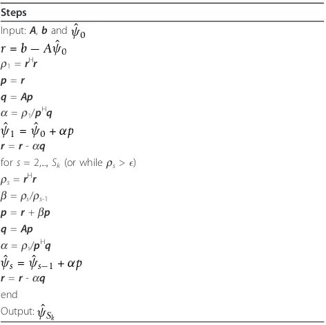
Looking at (7), it can be rewritten asb=Aψˆ, where
b=ΞˆHΔ−1r and A=ΞˆHΔ−1Ξˆ +C−ψ1. Without going into any further details, the algorithm for obtaining the approximate solutionψˆs, based on an initial guessψˆ0
and the subspace orderSk, is outlined in Table 1 as
pre-sented in [27]. In the first receiver iteration,ψˆ0is set to be the all one vector, while in the following iterations, the estimate from the previous receiver iteration is used. Note that the subspace order can either be fixed, or an error threshold could be used as a stopping criteria. The former is chosen here in order to get a fixed algo-rithm runtime and complexity.
3.3 SAGE based estimator (SAGE ML)
Even though the Krylov subspace method can signifi-cantly reduce the complexity of the joint MMSE estima-tor, the complexity is still high, since large matrix-vector multiplications are required in each Krylov iteration. A low-complexity alternative, which has shown good per-formance, is to use an algorithm based on EM/SAGE. In SAGE, given a received signal, the ML solution is itera-tively generated based on an underlying subspace model of the data. In [15] one such algorithm was presented, producing an optimal low-rank MMSE estimate of the channel. The details of that algorithm are outlined below, where a conversion from EM to SAGE has been performed.
The algorithm is processing one receive antenna chan-nel at the time, based on the following underlying model for the channel between userkand receive antennan,
rk,n[s] =Xk[s]Uψk,n+wk[s], k= 1, 2, ...,K, (8) wherew[s] = Σkwk[s] is the complete noise vector. As
can be seen,rk,n[s] is the signal contribution from user k, and summing over all users gives (2). For the problem
at hand, the SAGE algorithm is formulated as [15,26]
- Initialization: For allkands
ˆ
stems from the low-rank MMSE estimator, and in (13) averaging is performed to make use of the assumption that the channel is static within a block.
The value of Xk [s] is only perfectly known at time
instances where pilots are transmitted. On all other positions, symbol estimates must be used. The estimates are updated by the SISO decoders in every iteration, using the most recent channel estimate. Here, hard deci-sions Xˆk[s] = sign
˜
Xk[s] of the decoded soft symbols are used for channel estimation, and soft for interfer-ence cancellation.
At the very first receiver iteration, no channel estimate is available. Therefore, the algorithm is initialized with ˆ
s(0)k,n[s] =Xk[s]1M. Furthermore, to improve the accuracy of the initial estimate, several internal iterations can be performed within the estimator itself. This can be seen as the algorithm being reinitialized with its own updated channel estimate, without waiting for updates on the symbol estimates. In this article, this is only performed
at the initial pilot based stage, where the gain is observed to be the largest. In later stages, multiple inter-nal iterations are not producing any significant gain, thus mainly adding to the computational complexity.
4 Soft-input soft-output MU detectors
With estimates of the transmission channel having been made available by the channel estimator, the next stage of the iterative receiver structure is to produce likeli-hood-ratios of the coded data symbols. This operation is performed by the MUD, which apart from the received signal and channel estimate, usesa-prioriinformation of the transmitted symbols. This information is provided, from the previous iteration, by the channel decoder. The optimal SISO detector is the symbol-wise MAP detector, implemented through the BCJR algorithm [28]. Unfortunately, the complexity of the MAP detector in the MIMO case is prohibitive in most situations, except for the cases when the number of users K is small. Therefore, reduced complexity techniques have to be considered for most practical applications. Furthermore, although optimal detection is not generally feasible in practice, it remains important as a benchmark reference, and will therefore be considered in this article. The principles behind the MAP algorithm are outlined in Section 4.1.
Many reduced complexity detection algorithms have been proposed in the literature [2]. To restrict the inves-tigations, two such algorithms have been selected and are presented in Section 4.2. Both algorithms are based on PIC. The first algorithm applies a matched filter (MF) after the cancellation, while the other applies an MMSE filter, in an attempt to further suppress the inter-user interference. While the latter approach yields better performance it is also more complex. In later sec-tions we shall investigate whether the performance gain motivates the increased complexity.
4.1 Maximum a-posteriori probability
As stated previously, the optimal MUD is the symbol-wise MAP detector. While the PIC-based algorithms, being introduced in Section 4.2, only make use of the mean values x˜k[m,s], the symbol-wise MAP detector works with the probability mass function of x[m,s], denotedPa(x[m, s]).
In the case of QPSK transmission, the data vector x [m, s] contains 2Kcode bits,c1,..., c2K. The MAP
detec-tor computes the marginal mass functions, represented by log-likelihood ratio (LLR) values, for these 2Kbits:
As was discussed above, the complexity of the symbol-wise MAP detector (16) may in many cases be prohibi-tively large, showing the demand for low complexity schemes.
4.2 PIC based detectors
A popular low-complexity approach is to make use of interference cancellation. Though simple in their imple-mentation, PIC based detectors have shown good per-formance [8,10,29]. The interference cancellation is operating separately on each subcarrier and OFDM symbol, and makes use of the most recent channel esti-mate H[m]ˆ , and soft symbol estimates x[m,˜ s]from the SISO decoders. Following the notation in (1), the inter-ference cancelled output for userkis given by
˜
rk[m,s] =r[m,s]− ˆH[m]x˜=k[m,s], (17) wherex˜=k[m,s]is equal tox[m,˜ s], except for elementk, which is set to zero. A filtering of the signal˜rk[m,s]is then applied to produce an estimate of the transmitted symbol
xk[m, s]. A mapping to LLR values then follows.
The first algorithm, which will be referred to as PIC-MF, applies a MF to the interference cancelled output, i.e.,
˜
wherehˆk,:[m]is an estimate of the channel between user kand the base-station. In case of QPSK, the com-plex valued LLRs (with one symbol per comcom-plex dimen-sion) are produced as
Λk[m,s] =
is the variance of the residual interference plus noise for userk.
The drawback of PIC-MF is that the noise and resi-dual interference is not taken into account when per-forming user separation. To alleviate this problem, an MMSE filter can be applied instead of the MF. The resulting algorithm will be referred to as PIC-MMSE. An appropriate MMSE filter can be shown to yield [8]
ˆ
The output of the MMSE filter can be modeled as ˆ
The complex LLR output is then produced as
Λk[m,s] =
When it comes to practical implementations of iterative MU receivers, complexity considerations are of great importance. Since several receiver iterations are generally needed to reach a desired performance, the total computa-tional effort can grow very large. To get an estimate of this cost, we have chosen to present and compare the complex-ity of the addressed algorithms in terms of the required number of complex-valued multiplications. This measure is chosen since it provides a reasonable estimate of the complexity, while being analytically tractable. Obviously, the final computational and hardware complexity depends on a large number of parameters, such as memory require-ments, parallelization, hardware reuse, word lengths, etc.
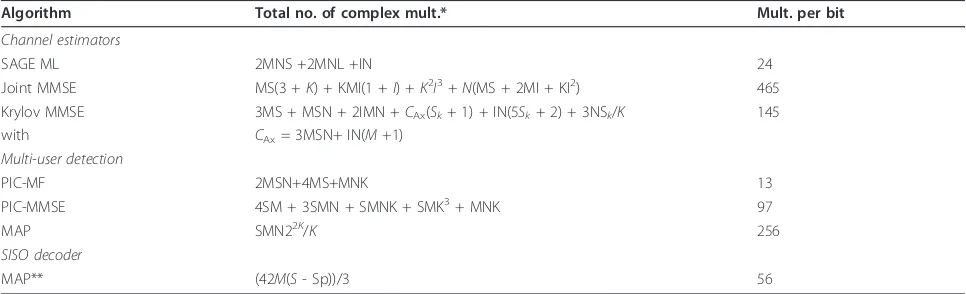
In the following sections, the complexities of the algo-rithms for both MUD and channel estimation are pre-sented. The expressions for the complexity of the SISO decoder, not being treated in a separate section, is given as derived in [30]. The expressions for the complexity per user of the various algorithms are given in Table 2, where the required number of complex multiplications per user is shown. Also given in the table is an example of the required number of multiplications per information bit, given QPSK modulation and rate 1/2 convolutional code, for the following system settings;N= 4 receive antennas,
K= 4 users,S= 20 OFDM symbols,Sp= 1 OFDM pilot
symbol,M= 256 subcarriers andI= 36 DPS sequences. Note that the DPS sequences, which are used for channel estimation, are assumed to be precalculated and read from memory, thus their construction does not contri-bute to the computational complexity.
5.1 Channel estimator complexity
SAGE ML. As seen in Table 2, the difference in com-plexity is significant. For the discussions below, we will assume that the number of OFDM symbols in each block is smaller than the number of subcarriers, i.e.,
S<M.
Looking at the first algorithm, the optimal joint MMSE algorithm, the complexity is large, as previously dis-cussed. Since all user channels are estimated jointly, using all available frequency and time samples, the dimensionality of the problem to solve becomes very large. Looking at (7), a straightforward implementation would be very costly due to the dimensionality of the involved data structures. Fortunately, considerable reduc-tions can be achieved. Firstly, under the assumption of independent receive antenna channels, the same estima-tor can be used independently on each antenna. Sec-ondly, under the block fading assumption, the matrix Ξ=X¯NU¯Nis the product of a block diagonal matrix and a block matrix with diagonal sub-matrices. Thus, the operations involving this structure can be computed effi-ciently. It should be noted that under the assumption of independent receive antennas,Ξis block diagonal with identical sub-matrices. The estimator only involve one of theseSM×KIsubmatrices. In the end, the main part of the complexity is related to two operations; the product ofΞˆH
Δ−1Ξˆ and the inverse operation of a KI × KI
matrix. The computational complexity of the former is approximatelyM(IK)2, while approximately (KI)3for the latter. For the system settings considered in this article the two are of comparable size. Also note that the hermi-tian properties of the data structures can be exploited to further reduce complexity.
The second algorithm make use of a Krylov subspace method to avoid the explicit matrix inversion in (7). At the same time the explicit computation ofΞˆH
Δ−1Ξˆ can
be avoided. This will be beneficial as long as S <M. Referring back to Section 3.2 and Table 1, the main part of the complexity lies in calculatingAvs, which is
per-formed once for every subspace dimensionSK. From a
complexity point of view, its preferable to keep SKlow.
On the other hand, a too small value will provide a poor approximation of the matrix inverse, and thus poor performance. The value thus needs to be chosen with care, trading complexity for performance. An upper limit on the number of dimensions may be set by timing constraints in the receiver.
The last algorithm, based on SAGE, has the lowest complexity and performs a separate channel estimate for each user channel. SAGE ML has less then half the com-plexity of Krylov MMSE withSK = 1. This suboptimal
approach has an attractively low complexity and, as will be seen in Section 6, also delivers good performance. The complexity is linear in the number of user, i.e., the plexity per user is constant. The main part of the com-plexity is shared between the per symbol estimate, the interference cancellation, and the subspace filtering, i.e., the utilization of the frequency correlation.
The former two is proportional to the number of OFDM symbolsS, while the latter to the subspace order
I, all with the same proportionality constant. The com-plexity can thus be reduced by lowering the number of OFDM symbols taken into account when performing the estimation, or by reducingI. Both actions would come at the price of a performance loss.
5.2 MUD complexity
As for the different channel estimation algorithms, the complexity of the considered MUDs differ significantly, as seen from Table 2. The one with the lowest complex-ity is the PIC-MF, which due to its simpliccomplex-ity requires Table 2 Expresions for the complexity per user for the different receiver components, as well as the required number of complex multiplications per information bit
Algorithm Total no. of complex mult.* Mult. per bit
Channel estimators
SAGE ML 2MNS +2MNL +IN 24
Joint MMSE MS(3 +K) + KMI(1 +I) +K2I3+N(MS + 2MI + KI2) 465 Krylov MMSE 3MS + MSN + 2IMN +CAx(Sk+ 1) + IN(5Sk+ 2) + 3NSk/K 145
with CAx= 3MSN+ IN(M+1)
Multi-user detection
PIC-MF 2MSN+4MS+MNK 13
PIC-MMSE 4SM + 3SMN + SMNK + SMK3+ MNK 97
MAP SMN22K/K 256
SISO decoder
MAP** (42M(S- Sp))/3 56
The latter is given for the case ofN= 4 receive antennas,K= 4 users,M= 256 subcarriers,S= 20 andSp= 1 OFDM symbol, andI= 36 DPS sequences. Further,
QPSK and a code rate of 1/2 is assumed. The subspace order in Krylov MMSE is set toSK= 5.
*The expressions are given per user and per transmitted data block.
relatively few arithmetic operations. The complexity is shared between the interference cancellation plus MF, and generating the LLRs. The former requiring a bit more computational effort. Despite its low complexity, as will be seen in Section 6, the performance is still competitive at low user loads.
Using a soft information based MMSE filter instead of the MF, the performance will be shown to improve. This comes at a cost of an increased complexity due to the MMSE filter in (21) which needs to be calculated for each user and for each data symbol. The filter includes an inverse of aK×Kmatrix. At high user loads, computing the inverse will dominate the complexity. If the number of users grow very large, subspace methods as the one used in the Krylov MMSE estimator could be used to reduce the complexity.
If the optimal MAP receiver is considered, the complex-ity is significantly increased. The complexcomplex-ity, as derived in [31], grows exponentially in the number of users. For few users, the complexity is manageable, but as the number of users grows, it rapidly becomes prohibitive. It should be noted that there exist a number of reduced complexity MAP-like detectors which are based upon searching trees [32,33], which are not included in our comparison.
6 Simulation results
In order to investigate the receiver performance under the use of the different algorithms, computer simulations were performed. In the simulations, each user transmits
S= 20 OFDM symbols, each withM= 256 subcarriers. If nothing else is stated, a single OFDM symbol is dedicated for training information, i.e.,Sp= 1, which is generated
randomly for each user. Non-orthogonal transmission of the pilot symbols are assumed, i.e., all users transmit their pilot symbols simultaneously in time and frequency. This may incur a loss in performance, but is motivated by the flexibility it brings to the system configuration if varying number of users is to be supported. A rate 1/2 convo-lutional code with generator polynomial (7, 5)8is
used to generate the code bits, which after random inter-leaving are mapped to QPSK symbols. For the receiver, we are restricting the investigation toN= 4 antennas, while different number of transmitting users are considered.
A fading multi-path IID channel is assumed, mimick-ing a rich scattermimick-ing environment. The channel impulse response between userkand receive antennanis given by [34]
whereap,k,nare zero-mean complex Gaussian random
variables with an exponential power delay profile,
θτp,k,n =Ce−τp,k,n/τrms, where C is a constant, and the delaysτp,k,nare uniformly distributed within the CP. In
this article, the length of the channel, normalized to the symbol duration, is τmax= 0.1, the root mean square
delay spread set to τrms = 0.03, and the number of
multi-path componentsP = 100. The channel delay is assumed to be no longer than the CP, and the block fading channel is generated independently for each user and receive antenna link. The number of DPS sequences used in the channel estimation process is chosen asI= 36, guided by the discussion in Section 2.2, and adding a few for improved performance at high SNR. The sub-space order in Krylov MMSE estimator is set to Sk= 5,
if nothing else is stated.
In the following, the motive behind performing the complex operation of channel estimation in the loop of an iterative receiver is first illustrated with an example. In the example, the average BER performance at different
Eb/N0is compared for receivers using the channel
esti-mator inside or outside of the iterative loop. It will be seen that the gains by performing the estimation inside the loop can provide significant performance gains. Here,
Ebis the average bit energy at the receiver. Furthermore,
the impact of the array gain has been removed by scaling the noise variance byN.
We then study the evolution of the BER and MSE of the channel estimate, over the receiver iterations. This is done for different user loads. The results illustrate the difference in convergence speed of the different receiver configura-tions, which is important when assessing the total compu-tational complexity needed to reach a certain level of performance. Finally, the convergence analysis is extended with the use of EXIT charts; providing additional insight on the receiver.
6.1 Illustration of the gains of using channel estimation inside the detection loop
As was seen in Section 5, performing channel estima-tion adds significantly to the total receiver complexity. Furthermore, having the estimation inside the loop of an iterative receiver, this costly operation needs to be performed multiple times. It would therefore, from a complexity point of view, be attractive to move the estimation outside the loop, only performing it once for each code block based on the transmitted pilot symbols.
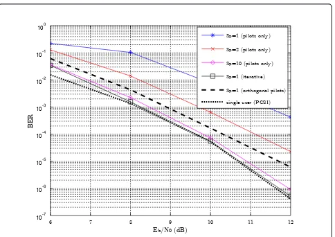
the MAP MUD is used in combination with the joint MMSE channel estimator. In Figure 2, the BER perfor-mance is shown for different number of pilot symbols transmitted. For the purely iterative receiver, only one pilot OFDM symbol is used, while for the other receiver
Sp= 1,2 and ten pilot symbols are transmitted. For
com-parison, single user performance when perfect channel state information (PCSI) is available at the receiver is also shown. Also, an example with orthogonal pilots is pro-vided, where the users consecutively transmit one pilot symbol each during the first four symbol intervals. Each pilot have been boosted, containing the equivalent energy of four regular symbols.
As seen from the figure, if only pilot based estimates are used, there is a significant performance loss, as com-pared to when using channel estimation in the iterative loop. For few pilot symbols, a loss in performance of 1-3 dB is observed, while if the number of pilot symbols is increased toSp= 10, the loss is small. Remember that the
total number of OFDM symbols in a block isS= 20, thus transmitting ten symbols yields a 50% pilot overhead, which is unacceptable for most applications. Transmit-ting orthogonal boosted pilots also result in a loss of up to 1 dB. The performance achieved with orthogonal pilots is only slightly better than when transmittingSp=
4 non-orthogonal pilots, since joint channel estimation is performed. Furthermore, if iteratively updating the chan-nel estimates, close to single user performance with PCSI is achieved. It can therefore be concluded that the use of channel estimation inside an iterative receiver can give significant performance gains, as compared to pure pilot based approaches. This means that pilot density can be kept low, without sacrificing performance, thus improv-ing the system throughput.
6.2 Convergence performance: BER and MSE
In the previous section we illustrated how iterative chan-nel estimation can provide a significant performance
Eb/N0 (dB)
BER
6 7 8 9 10 11 12
10-7 10-6 10-5 10-4 10-3 10-2 10-1 100
Sp=1 (pilots only)
Sp=2 (pilots only)
Sp=10 (pilots only)
Sp=1 (iterative)
Sp=1 (orthogonal pilots)
single user (PCSI)
Figure 2The BER at differentEb/N0forN= 4 receive antennas andK= 4 users. Different number of pilot OFDM symbols are used,Sp=
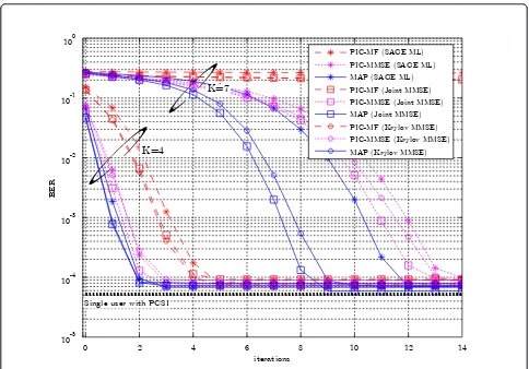
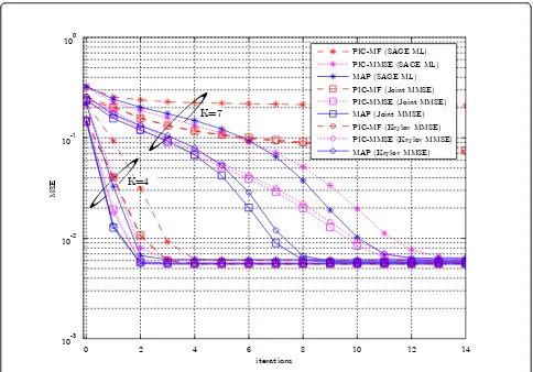
gain. At the same time, the complexity can be significant, as seen in Section 5. Since the computational cost increases linearly with the number of iterations, the con-vergence properties of the different receiver configura-tions are of importance. To illustrate their properties, the BER as well as the MSE is shown, as a function of the number of iterations, in Figures 3 and 4, respectively. The results are shown for the cases ofK= 4 and 7 users, at anEb/N0= 10dB.
Starting with the BER in Figure 3, it is clear that con-vergence properties differ between algorithm combina-tions. At the smaller user load, i.e.,K= 4, the difference in convergence is relatively small, with all algorithms reaching roughly the same BER within 3-8 iterations. The fastest convergence is achieved using the MAP based MUD with joint MMSE channel estimation, while the slowest is obtained if using the PIC-MF detector with SAGE ML estimation. By using the MMSE Krylov esti-mator withSK= 5, a small performance loss as compared
to joint MMSE is observed. Increasing this value toSK=
10, close to joint MMSE performance has been observed. Looking at a system load of K = 7 users, a similar
behavior as withK= 4 is seen. Comparing the perfor-mance achieved when using the different MUDs, the best performance is given by the MAP. A gain of 1-5 itera-tions over the PIC-MMSE detector is observed. There is a large difference in convergence depending on which estimator is used, and additional insight on this will be given when looking at the EXIT charts in the next sec-tion. Furthermore, at this high user load, the PIC-MF can not provide sufficient detection performance for receiver convergence. It is also interesting to note that perfor-mance close to that of a single user with PCSI at the receiver is achieved for all receiver configurations, except for PIC-MF atK= 7 users. This illustrate the good per-formance obtained by the iterative receiver.
Looking at the average MSE, as shown in Figure 4, similar trends as for the BER are seen. The convergence speed of the joint MMSE estimator is better than that of SAGE ML, and the difference increases with the user load. Furthermore, in the first iteration, only pilot sym-bols are used for channel estimation, and a large MSE is obtained due to the relatively small number of available pilots. In the iterative process, as the reliability of the
iterations
BER
0 2 4 6 8 10 12 14
10-5 10-4 10-3 10-2 10-1 100
PIC-MF (SAGE ML)
PIC-MMSE (SAGE ML) MAP (SAGE ML) PIC-MF (Joint MMSE) PIC-MMSE (Joint MMSE) MAP (Joint MMSE) PIC-MF (Krylov MMSE) PIC-MMSE (Krylov MMSE) MAP (Krylov MMSE)
Single user with PCSI
K=7
K=4
symbol estimates increases with iterations, so does the accuracy of the channel estimate.
6.3 Convergence performance: EXIT charts
Even though the BER and MSE convergence provide some insight on the behavior of the different algorithms, they have some limitations. One significant drawback is that the performance of the channel estimation and detection algorithms cannot be separated from that of the code. Other means are therefore of interest for the receiver evaluation.
One popular technique for visualizing the convergence behavior of iterative decoders is the EXIT charts [16]. The charts are used to visualize the exchange of extrinsic infor-mation between the SISO units making up an iterative decoder. In [35], it was shown that the MUD could be seen as SISO unit being serially concatenated with the outer channel decoder. In our case, we have three units, the MUD, the channel estimator and the decoder. Even though it is possible to visualize the exchange between all three SISO units [36,37], it is more convenient to combine
the estimator and the MUD into a single SISO unit [38], referred to as MUD/CE.
In order to produce an EXIT chart, information trans-fer functions of the SISO units have to be produced. Each unit can be seen an LLR transformer (Λa ®Λext),
where the transfer function measures the improvement of the LLR-transformation in terms of mutual informa-tion between the LLRs and the underlying variables x. The transfer function is given as [39]
Iext=T(Ia), (23)
whereIa=I(x;Λa) is thea priori input mutual
infor-mation and Iext = I (x; Λext) is the output extrinsic
information.
When producing the transfer functions, all elements of Λext(becoming Λafor the next component decoder) are
assumed independent and to follow a Gaussian distribu-tion, Nxμext,σext2 , with consistency condition μext=σext2 /2and wherex= ±1. With this distribution of the LLRs, there is a one-to-one mapping between the mutual informationIextand the varianceσext2 given by
iterations
MSE
0 2 4 6 8 10 12 14
10-3 10-2 10-1 100
PIC-MF (SAGE ML)
PIC-MMSE (SAGE ML)
MAP (SAGE ML)
PIC-MF (Joint MMSE)
PIC-MMSE (Joint MMSE) MAP (Joint MMSE)
PIC-MF (Krylov MMSE)
PIC-MMSE (Krylov MMSE)
MAP (Krylov MMSE) K=7
K=4
Iext=J(σext), (24) where theJ-function is defined in [16]. When generat-ing the transfer functions, theJ-function is used for
gen-erating input sequences with different a priori
information content. More specifically, given an input symbolx, and a value for thea priori informationIa, the
input LLRs are given by
Λext(Ia)= σ
For the MUD/CE, as shown in Figure 1, the transfer function is now derived for a number ofIextÎ[0,1]. We
first generate the soft input symbolsx˜k= tanh
Λext(Ia)/2 and the known pilot symbols for all users. After QPSK mapping, channel estimation and MUD is performed. The LLR output generated by the MUD is then feed to a sink, where the mutual information is computed through [39]
Iext=
approximated using histogram calculations. The transfer functions are then averaged over 20 channel realizations. The transfer function for the SISO decoder is obtained in a similar way.
When generating the transfer function for the MUD/ CE, the initial guess for the Krylov MMSE and SAGE ML has to be provided. In the receiver this value is given by the estimate obtained in the previous iteration. Since this value is unknown, we solve it by running the channel estimator twice, first initialized with the all one channel then reinitialized with the new output. This potentially leads to an over estimated performance at highIext. For SAGE ML this also leads to an under
esti-mated performance at low values.
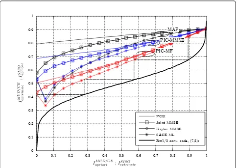
In Figure 5 the EXIT chart is shown for the different receiver combinations for the case of N = 4 receive antennas and K= 4 users atEb/N0 = 10 dB. The
trans-fer functions in the case of PCSI is also shown. Further-more, the convergence path for PIC-MF with SAGE ML estimation is shown as a dashed line, and the receiver is estimated to converge in five iterations. This coincides with the observation for the BER in Figure 3. For the receivers where SAGE ML is used, a dip is seen in the transfer function at low Ia. This occurs since the
algo-rithm is not taking the quality of the soft symbols into account, thus producing estimates based on very unreli-able hard estimates of the transmitted symbols. This dip could be partly removed if only pilots are considered (Ia
= 0) in the estimator if the reliability of the produced soft symbols are low.
Comparing the channel estimation algorithms, Krylov MMSE, used withSK = 5, delivers performance identical
to Joint MMSE. For SAGE ML, the performance is much worse, but the performance at lowIais somewhat
underestimated as discussed above. From Figure 5, we also see the impact of inaccurate CSI, illustrating itself by a gap between the transfer functions obtained when using the channel estimation and when having PCSI. As the reliability of the a prioriinformation increases, this gap is decreased since the produced estimates become increasingly accurate. Looking at the MUDs, the MAP obviously has the best performance, followed by PIC-MMSE and PIC-MF. Furthermore, when the SNR is reduced (essentially leading to downward shift of the transfer functions of the MUD/CE), or when increasing the user load (essentially changing the slope of the transfer functions), the PIC-MF will be the first MUD closing the gap to the SISO decoder transfer function, and thus failing to converge.
Overall, we see that the insight given by the EXIT chart matches fairly well with what was observed for the BER. Furthermore, observing the MAP detector for K= 7 users in Figure 3, large difference in convergence per-formance between using the MMSE estimators or SAGE ML was observed. This could be explained by the fact that the gap in the EXIT chart is smaller for the latter estimator. From a algorithm design point of view, it is also interesting to observe that for the case presented in Figure 5 there is still room for further simplifications of the receiver structure. Additionally, the performance obtained when using an alternative channel code can be estimated by replacing the transfer function for the cho-sen convolutional code in Figure 5.
7 Complexity versus performance trade-off
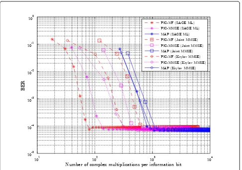
From a receiver design point of view, the trade-off between performance and complexity is an important aspect. In an attempt to shed some light on this aspect, the total receiver complexity, in terms of the number of complex multiplications, needed to reach a specific tar-get BER is investigated. The total complexity depends both on the choice of channel estimator and MUD, as well as on the number of iterations needed to reach the target. For the evaluation, a target BER of 10-3is chosen. The system settings are the same as described in Section 6, i.e.,N= 4 receive antennas,Sp= 1 andS= 20 OFDM
symbols, M = 256 subcarriers and I = 36 DPS
sequences. The subspace order in Krylov MMSE is set toSK = 5.
To start with, the case ofK= 4 users, signaling at an
plotted versus the number of complex multiplications, for the different combinations of the MUD and channel estimation algorithms.
As was previously seen in Figure 3, under these sys-tem settings, all receivers reach the same BER perfor-mance of ~10-4. On the other hand, looking at the number of multiplications needed to reach this value, there is more than an order of magnitude difference between the receiver configurations. The receiver con-figurations using the MAP detector is found on the right, requiring the largest number of multiplications to reach convergence. To the left, we find the PIC based MUDs using SAGE ML, providing the cheapest alterna-tive. Looking at the target BER of 10-3, the algorithms with the lowest total complexity is PIC-MF followed by PIC-MMSE. Reaching the target in about 70 and 100 complex multiplications per information bit, respec-tively. When using the MMSE Krylov estimator, we see that PIC-MF and PIC-MMSE reach the target using approximately the same number of multiplications, though PIC-MF require one more iteration.
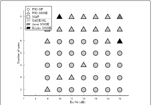
Finally, an overview of which algorithm combinations to choose in different scenarios is given. In Figure 7, the receiver configuration with the lowest total complexity, at different user loads andEb/N0, is shown for a target
BER of 10-3. The shape indicates which MUD that is used, while the color indicates the choice of channel esti-mation algorithm. Due to their large complexity, neither the MAP detector, nor the joint MMSE estimator are competitive in any of the evaluated scenarios - not even at high system loads. Note that eight users is at the bor-der of what the system can handle, still, even with sub-optimal algorithms, low BER can be achieved. Overall, the most favorable receiver configuration to use, from a complexity point of view, is the PIC-MF MUD combined with the SAGE ML estimator. At higher user loads though, the PIC-MMSE detector gives the best trade-off between complexity and performance. For channel esti-mation, using anything but SAGE ML is in general not required for the considered system.
The results shown in Figure 7 take the overall compu-tational complexity into account and may therefore fail to
0 0.1 0.2 0.3 0.4 0.5 0.6 0.7 0.8 0.9 1
0 0.1 0.2 0.3 0.4 0.5 0.6 0.7 0.8 0.9 1
MAP
PIC-MF PIC-MMSE
PCSI
Joint MMSE
Krylov MMSE
SAGE ML
R=1/2 conv. code, (7,5)8
show other interesting trade-offs. An example of this is seen in Figure 3, where the difference in convergence speed between the algorithms is large. Depending on the hardware architecture used, this may affect the latency of the system, and for time critical systems, the choice of algorithm combinations may therefore be another. We believe, however, that our evaluation shows that combi-nations of algorithms with low computational complexity, when used in an in an iterative receiver, can deliver very competitive performance for a large range of scenarios.
8 Conclusion
In this article, we have studied the trade-off between complexity and performance for uplink receivers in a packet based MU MIMO-OFDM system. The considered iterative receivers contained three main components; a MUD, a channel estimator and a con-volutional decoder. Three different MUD algorithms were considered, two suboptimal approaches based on PIC and one optimal based on MAP. For channel estimation, three algorithms were evaluated, one optimal joint MMSE based
estimator, a low complexity Krylov subspace based ver-sion of the same, and one sub-optimal based on SAGE. The difference in complexity between the algorithms were shown to be large.
When only considering performance, the high com-plexity algorithms naturally showed the fastest conver-gence. The low-complexity algorithms showed similar BER performance as the more complex ones, when con-verging, but at a generally slower convergence speed. More insight on the convergence was also provided through EXIT charts. When taking complexity into account, we demonstrate that the sub-optimal low-com-plexity algorithms are often the most attractive choice. Even though a larger number of receiver iterations were needed, the total number of complex multiplications was still lower, due to a significantly lower computational cost per-iteration. At the same time, it should be noted that the most simple receiver failed earlier than the others at high user loads, which indicates that an appro-priate balance between complexity reduction and perfor-mance needs to be achieved. Furthermore, for time Number of complex multiplications per information bit
BER
101 102 103 104
10-5
10-4
10-3
10-2
10-1
100
PIC-MF (SAGE ML) PIC-MMSE (SAGE ML) MAP (SAGE ML)
PIC-MF (Joint MMSE) PIC-MMSE (Joint MMSE) MAP (Joint MMSE) PIC-MF (Krylov MMSE) PIC-MMSE (Krylov MMSE)
MAP (Krylov MMSE)
critical systems where convergence speed is at focus, high complexity algorithms may be a better choice.
Endnote
a
In general the notation will be that sub-indices state which user and receive antenna is considered, while the time and frequency position will be given in brackets.
Competing interests
The authors declare that they have no competing interests.
Received: 15 May 2011 Accepted: 1 March 2012 Published: 1 March 2012
References
1. E Dahlman, S Parkvall, J Sköld, P Beming,3G Evolution HSPA and LTE for Mobile Broadband(Academic Press, Oxford, 2008)
2. EG Larsson, MIMO detection methods: how they work. IEEE Signal Process Mag.26(3), 91–95 (2009)
3. H Vikalo, B Hassibi, P Stoica, Efficient joint maximum-likelihood channel estimation and signal detection. IEEE Trans Wirel Commun.5(7), 1838–1845 (2006)
4. W Xu, M Stojnic, B Hassibi, On exact maximum-likelihood detection for non-coherent MIMO wireless systems: a branch-estimate-bound
optimization framework, inProc IEEE International Symposium on Information Theory, Toronto, Canada, 2017–2021
5. DJ Ryan, IB Collings, IVL Clarkson, GLRT-optimal noncoherent lattice decoding. IEEE Trans Signal Process.55(7), 3773–3786 (2007)
6. C Berrou, A Glavieux, Near optimum error correcting coding and decoding: turbo-codes. IEEE Trans Commun.44(10), 1261–1271 (1996). doi:10.1109/ 26.539767
7. X Wautelet, A Dejonghe, L Vandendorpe, MMSE-based fractional turbo receiver for space-time BICM over frequency-selective MIMO fading channels. IEEE Trans Signal Process.52(6), 1804–1809 (2004). doi:10.1109/ TSP.2004.827198
8. T Zemen, C Mecklenbrauker, J Wehinger, R Muller, Iterative joint time-variant channel estimation and multi-user detection for MC-CDMA. IEEE Trans Wirel Commun.5(6), 1469–1478 (2006)
9. P Salvo Rossi, R Müller, Slepian-based two-dimensional estimation of time-frequency variant MIMO-OFDM channels. IEEE Signal Process Lett.15, 21–24 (2008)
10. B Hu, I Land, L Rasmussen, R Piton, B Fleury, A divergence minimization approach to joint multiuser decoding for coded CDMA. IEEE J Sel Areas Commun.26(3), 432–445 (2008)
11. ME Honig,Advances in Multiuser Detection(Wiley, Hoboken, 2009) 12. P Hammarberg, F Rusek, O Edfors, Channel estimation algorithms for
OFDM-IDMA: complexity and performance. IEEE Trans Wirel Commun (in press)
Eb/N0 (dB)
Number of users
7 8 9 10 11 12 13 14 15
2 3 4 5 6 7 8
PIC-MF PIC-MMSE MAP SAGE-ML Joint MMSE Krylov MMSE
Figure 7Complexity-performance trade-off for the different algorithms, whenN= 4 receive antennas, at differentEb/N0and user
loads. The figure show the algorithm combination reaching a BER threshold of 10-3in the fewest number of complex multiplications. The shape
13. C Dumard, T Zemen, Low-complexity MIMO multiuser receiver: a joint antenna detection scheme for time-varying channels. IEEE Trans Signal Process.56(7), 2931–2940 (2008)
14. J Ketonen, M Juntti, J Cavallaro, Performance—complexity comparison of receivers for a LTE MIMO-OFDM system. IEEE Trans Signal Process.58(6), 3360–3372 (2010)
15. J Gao, H Liu, Low-complexity MAP channel estimation for mobile MIMO-OFDM systems. IEEE Trans Wirel Commun.7(3), 774–780 (2008) 16. S ten Brink, Convergence of iterative decoding. IEEE Electron Lett.35(10),
806–808 (1999). doi:10.1049/el:19990555
17. J Ylioinas, M Raghavendra, M Juntti, Avoiding matrix inversion in DD SAGE channel estimation in MIMO-OFDM with M-QAM, inProc IEEE Vehicular Technology Conference 2009 fall, Anchorage, AK, 1–5 (2009)
18. D Slepian, Prolate spheroidal wave functions, Fourier analysis, and uncertainty-V: the discrete case. Bell Syst Tech J.57(5), 1371–1430 (1978) 19. T Zemen, C Mecklenbrauker, Time-variant channel estimation using discrete
prolate spheroidal sequences. IEEE Trans Signal Process.53(9), 3597–3607 (2005)
20. O Edfors, S Wilson, P Börjesson, OFDM channel estimation by singular value decomposition. IEEE Trans Commun.46(7), 931–939 (1998). doi:10.1109/ 26.701321
21. SM Kay,Fundamentals of Statistical Signal Processing, Volume I: Estimation Theory, 1st edn. (Prentice Hall, Upper Saddle River, 1993)
22. P Salvo Rossi, R Müller, Joint iterative time-variant channel estimation and multi-user detection for MIMO-OFDM systems, inProc IEEE Global Communications Conference, Washington, DC, 4263–4268 (2007)
23. Y Li, N Seshadri, S Ariyavisitakul, Channel estimation for OFDM systems with transmitter diversity in mobile wireless channels. IEEE J Sel Areas Commun. 17(3), 461–471 (1999). doi:10.1109/49.753731
24. M Münster, L Hanzo, Parallel-interference-cancellation-assisted decision-directed channel estimation for OFDM systems using multiple transmit antennas. IEEE Trans Wirel Commun.4(5), 2148–2162 (2005) 25. T Zemen, M Loncar, J Wehinger, C Mecklenbrauker, R Muller, Improved
channel estimation for iterative receivers, Proc IEEE Global Communications Conference, San Francisco, CA,1, 257–261 (2003)
26. J Fessler, A Hero, Space-alternating generalized expectation-maximization algorithm. IEEE Trans Signal Process.42(10), 2664–2677 (1994). doi:10.1109/ 78.324732
27. R Barrett, M Berry, TF Chan, J Demmel, J Donato, J Dongarra, V Eijkhout, R Pozo, C Romine, H Van der Vorst,Templates for the Solution of Linear Systems: Building Blocks for Iterative Methods, 2nd edn. (SIAM, Philadelphia, 1994)
28. L Bahl, J Cocke, F Jelinek, J Raviv, Optimal decoding of linear codes for minimizing symbol error rate. IEEE Trans Inf Theory20(2), 284–287 (1974) 29. H Lee, I Lee, B Lee, Iterative detection and decoding with an improved
V-BLAST for MIMO-OFDM systems. IEEE J Sel Areas Commun.24(3), 504–513 (2006)
30. D Costello, A Banerjee, C He, P Massey, A comparison of low complexity turbo-like codes, inSignals Systems and Computers Conference Record of the Thirty-Sixth Asilomar Conference on, Pacific Grove, CA,1, 16–20 (2002) 31. S Roy, T Duman, Soft input soft output Kalman equalizer for MIMO
frequency selective fading channels. IEEE Trans Wirel Commun.6(2), 506–514 (2007)
32. J Boutros, N Gressety, L Brunel, M Fossorier, Soft-input soft-output lattice sphere decoder for linear channels, inProc IEEE Global Communications Conference, San Francisco, CA, 1583–1587 (2003)
33. KKV Wong, The soft-output M-algorithm and its applications, Dept, Electrical and Computer Eng, Queens University, Canada, Ph.D. thesis (2006) 34. P Hoeher, A statistical discrete-time model for the WSSUS multipath
channel. IEEE Trans Veh Technol.41(4), 461–468 (1992). doi:10.1109/ 25.182598
35. P Alexander, AJ Grant, MC Reed, Iterative detection in code-division multiple-access with error control coding. Eur Trans Telecommun.9(5), 419–425 (1998). doi:10.1002/ett.4460090504
36. F Brännström, L Rasmussen, A Grant, Convergence analysis and optimal scheduling for multiple concatenated codes. IEEE Trans Inf Theory51(9), 3354–3364 (2005). doi:10.1109/TIT.2005.853312
37. D Shepherd, Shi Z, M Anderson, M Reed, EXIT chart analysis of an iterative receiver with channel estimation, inProc IEEE Global Communications Conference, Washington, DC, USA, 4010–4014 (Nov. 2007)
38. R Otnes, M Tüchler, EXIT chart analysis applied to adaptive turbo equalization, inProc 5th Nordic Signal Processing Symp, Hurtigruten from Tromso to Trondheim, Norway (2002)
39. S ten Brink, Convergence behavior of iteratively decoded parallel concatenated codes. IEEE Trans Commun.49(10), 1727–1737 (2001). doi:10.1109/26.957394
doi:10.1186/1687-1499-2012-75
Cite this article as:Hammarberget al.:Iterative receivers with channel estimation for multi-user MIMO-OFDM: complexity and performance.
EURASIP Journal on Wireless Communications and Networking20122012:75.
Submit your manuscript to a
journal and benefi t from:
7Convenient online submission
7Rigorous peer review
7Immediate publication on acceptance
7Open access: articles freely available online
7High visibility within the fi eld
7Retaining the copyright to your article