ISSN 2286-4822 www.euacademic.org
Impact Factor: 3.4546 (UIF)
DRJI Value: 5.9 (B+)
Design of Multi-Rate Viterbi Decoder with Variable
Constraint Length for Software Defined Radios
MUHAMMAD ASLAM
International Islamic University H-10, Islamabad Pakistan
Abstract:
Software defined radio (SDR) demands reconfigurable encoders and decoders. In case of fixed constraint length Viterbi decoding, it is difficult to implement this decoder in software defined radio. The main aim of this paper is the design and implementation of soft Viterbi decoder with variable constraint lengths and code rates. In this paper, Viterbi decoder with constraint lengths of 3, 4, 7, and code rates of 1/2, 2/3, ¾ is implemented. In order to make the design more efficient in terms of processing time, a correlation is used instead of the conventional Euclidean distance method. The proposed design of encoder and Viterbi decoder is implemented in MATLAB and the results are compared with the results of built-in functions of MATLAB.
Key words: Convolutional Encoder, Viterbi Decoder, Matlab,
Software Defined Radio.
Introduction
limited number of errors occurring anywhere in the message without the need to ask the sender for additional data. FEC gives the receiver an ability to correct errors without needing a reverse channel to request retransmission of data, but this advantage is at the cost of a fixed higher forward channel bandwidth. FEC is, therefore, applied in situations where retransmissions are relatively costly, or impossible such as when broadcasting to multiple receivers. The process of adding this redundant information is known as channel coding. Convolutional coding and block coding are the two major forms of channel coding (FEC). Convolutional codes operate on serial data, one or a few bits at a time. Block codes operate on relatively large message blocks. There are a variety of useful Convolutional and block codes, and a variety of algorithms for decoding the received coded information sequences to recover
the original data [1‒3].
Convolution encoder with Viterbi decoder is a powerful method for forward error correction technique. The principle of Viterbi algorithm is based on maximum likelihood decoding. Basic block diagram for convolution encoder followed by Viterbi decoder with addition of Additive White Gaussian Noise (AWGN) is shown in Figure1. Input data stream is fed to the convolution encoder, which produces encoded output stream according to designed encoder specification. The encoded data steam travels through channel having presence of noise and produces a new encoded stream with noise. Finally, this noisy data is given to the Viterbi decoder that produces the corrected data which is applied to the encoder as input [4].
Figure 1. Basic block diagram of channel coding NOISE
ENCODER DECODER
The purpose of this paper is to implement the Convolutional encoder along with hard and soft Viterbi decoder having constraint lengths of 3, 4, and 7 and with rates of 1/2, 2/3, 3/4. The result is compared with the result of MATLAB built-in function.
I. Convolutional Encoder
When it comes to protecting the digital data from errors, Convolutional coding is a very suitable candidate for it. In this technique, the encoder adds sufficient redundancy to the message in order to transmit the data free of errors. Convolutional encoder is defined by its two parameters i.e. code rate, and constraint length. The code rate of this encoder is defined as the ratio of number of input symbols (k) to the number output symbols (n) of this encoder. The second parameter is the length of the Convolutional encoder called constraint length (K), which is equal to K=m+1, where „m‟ is number of memory units (flip flop) in the encoder [5].
II. Viterbi Algorithm
In order to recover the possible transmitted sequence from the received sequence, the Viterbi algorithm calculates the metric value using trellis diagram. On the basis of quantization levels, the Viterbi decoding algorithm is classified into two categories:
i. Hard Viterbi decoder
ii. Soft Viterbi decoder
If there are two quantization levels at the decoder, the resultant decision making of the decoder is called hard decision, whereas for more than two quantization levels, the decision making of the decoder is called Soft decision [6].
requires more memory than hard decision decoding. After receiving the data at the receiver end, there appears a need to extract the original sending sequence. In order to accomplish that task, Viterbi algorithm makes use of „trellis diagram‟ which is shown in Figure 2. To detect the original sequence, the most likelihood path of the diagram is identified, which is the path with least metric value. Each node of the trellis diagram represents a state at a given time, and a possible data sequence is formed by tracing back from that node to the initial state [7].
Figure 2. Trellis diagram
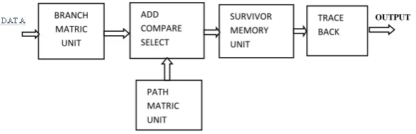
III. Structure of Viterbi Decoder
As shown in Figure 3,the decoder is divided into the sub modules: BMU, PMU, and SMU.
Figure 3. Viterbi decoder’s structure
A. BRANCH METRIC VALUE UNIT (BMU)
In this unit, the received bits (code symbols) are compared with the expected bits (code symbols). In case of hard Viterbi
BRANCH MATRIC UNIT
ADD COMPARE SELECT
SURVIVOR MEMORY UNIT
TRACE BACK
PATH MATRIC UNIT
decoder, Hamming distance is used for bit comparisons while, for soft Viterbi decoder, Euclidean distance is used for bit comparison [8].
B. PATH METRIC VALUE UNIT (PMU)
Two adders of add-compare-select module calculate the partial path metric. Afterwards, comparison of partial path metrics takes place by the comparator. Then, the selector selects the branch with least metric value and corresponding bit decision (states) is transferred to SMU [9].
C. SURVIVOR MEMORY PATH UNIT (SMU)
After collecting data from PMU, Survivor Memory Unit generates the decoded sequence. When the trellis diagram ends, Trace-back is processed to find the most likelihood path from final stage to initial stage of trellis diagram.
IV. Puncturing
Puncturing uses the basic principle of deleting some bits out of an encoded sequence. Similarly, we generate punctured codes as follows:
i. At first the data is encoded using a rate of 1/n encoder. ii. Afterwards, some of the channel symbols are deleted from the output of this encoder.
For example, 3/4 code rate can be created from the rate 1/2 code, the following puncturing pattern is used for this purpose:
1 0 1
1 1 0
Figure 4. 3/4 code rate
We can also generate a 2/3 code rate using a rate of 1/2 encoder by using following table:
1 1
1 0
Figure 5. 2/3 code rate
The above pattern has two columns and three ones. As shown in the previous example, here also think of each column representing a bit input of encoder and each „1‟ representing an output channel symbol. Hence, a rate of 2/3 code is generated from the rate of 1/2 code, as there are two columns and three ones in the above table. Just as „0‟ represents a deleted symbol at the encoder level, at the input of Viterbi decoder null symbols are substituted in the place of deleted symbols in order to decode the received data.
V. Proposed Design Model
To implement a Viterbi decoder, one must create some steps on which the algorithm of decoder will work. Generally, the best implementation of these data structures is possible by using arrays. In order to implement the Viterbi decoder, one needs to have six primary arrays. These arrays are given as follows:
Next state table of Viterbi decoder. This table has
dimensions which are 2(K - 1) x 2k(rows x columns). Before
starting the decoding process, it is essential to initialize this table.
Output table of the decoder. This table has dimensions
which are 2(K -1) x 2k. Before starting decoding process,
this array must also be initialized.
Input table of the decoder. This table has dimensions
which are 2(K - 1) x 2(K - 1). Before starting the decoding
process, this array must also be initialized.
1) received channel symbol pairs. The dimensions of this
array are 2 (K - 1) x (K x 5 + 1). Unlike the previous arrays,
this array does not need to be initialized during the start of the decoding process.
Accumulated metric value table of the decoder. The objective of this table is to accumulate the accumulated metric values for each state which are calculated with the help of the add-compare-select module of the
decoder. This table has dimensions which are 2 (K - 1) x (K
x 5 + 1). This array does not need to be initialized during the start of the decoding process.
Trace back array of the decoder. This array accumulates the list of states identified in trace back path. The dimension of this array is (K x 5) +1. This array is not needed to be initialized during the start of the decoding process.
VI. Discussion and Results
Euclidean distance is given as
√ (1)
and correlation is given as
[ ] (2)
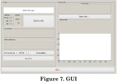
The above correlation is very efficient and fast performing as compared to the Euclidean distance method because of less hardware consumption. In this paper, therefore, the above correlation is used for calculating the metric value in Soft Viterbi decoder instead of Conventional Euclidean distance. The proposed design is also implemented in MATLAB, and the results of the Viterbi decoder proposed in this paper match with the results of MATLAB built-in functions.
As shown in Figures 7‒11, the error correcting
capabilities of proposed Soft Viterbi decoder and the conventional Soft Viterbi decoder are almost same, but the proposed design performs faster than the conventional Soft Viterbi decoder that uses Euclidean distance for the calculation of metric value.
Figure 8. Results of Proposed design
Figure 9. Hard Viterbi Decoder with code rate ½
Figure 10. Soft Viterbi Decoder With code rate 1/2
0 1 2 3 4 5 6 7
10-5 10-4 10-3 10-2 10-1 100
Eb/No, dB
B
it
E
rr
o
r
R
a
te
BER for BCC with Viterbi decoding for BPSK in AWGN
matlabcoded
simulation - Viterbi (rate-1/2, [133,171] 64) theory - uncoded
0 1 2 3 4 5 6 7 8
10-5 10-4 10-3 10-2 10-1 100
Eb/No, dB
B
it
E
rr
o
r
R
a
te
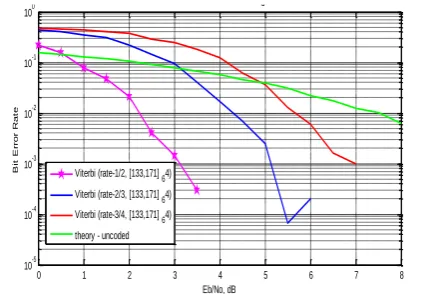
Figure 11. Soft Viterbi decoder with code rate 1/2, 2/3, 3/4.
REFRENCES
[1] Shannon, C. “A mathematical theory of
Communication”, Bell Sys. Tech .J, vol. 27, pp. 379-423 and 23-656, 1948.
[2] V. Kavinilavu, S. Salivahanan, V. S. Kanchana
Bhaaskaran, Samiappa Sakthikumaran, B. Brindha and C. Vinoth, “Implementation of convolutional encoder and viterbi decoder using verilog HDL”, IEEE trans. ICECT, vol. 1, pp. 297-300, April 2011.
[3] Swati Gupta, rajesh Mehra, “FPGA Imeplementation Of
Viterbi Decoder using Trace Back Architecture”, International Journal of Engineering Trends and Technology, pp. 131-134, June 2011
[4] Chip Fleming, “A tutorial on convolutional coding with
viterbi decoding”, 2011.
[5] Yin Sweet Wong, Wen Jian Ong, Jin Hui Chong, Chee
Kyun Ng, Nor Kamariah Noordin,” Implementation of Convolutional Encoder and Viterbi Decoder using VHDL” Research and Development (SCOReD), 2009 IEEE Student Conference on, IEEE, Nov. 2009, ISBN:978-1-4244-5186-9
0 1 2 3 4 5 6 7 8
10-5 10-4 10-3 10-2 10-1 100
Eb/No, dB
B
it
E
rr
o
r
R
a
te
BER for BCC with Multirate Soft Viterbi decoding for BPSK in AWGN
Viterbi (rate-1/2, [133,171] 64)
Viterbi (rate-2/3, [133,171] 64) Viterbi (rate-3/4, [133,171] 64)
[6] Wong, Y.S. et.al “Implementation of convolutional encoder andViterbi decoder using VHDL” IEEE Tran. on Inform. Theory,pp. 22-25, Nov. 2009.
[7] Irfan Habib, Özgün Paker, Sergei Sawitzki, “Design
Space Exploration of Hard-Decision Viterbi Decoding: Algorithm and VLSI Implementation” IEEE Tran. on Very Large Scale Integration (VLSI) Systems, Vol. 18, Pp. 794-807, May 2010.
[8] Bupesh Pandita, "Design and Implementation of a
Viterbi Decoder using FPGAs". M.Tech thesis,
Department of Electrical Engineering, IIT Kanpur, 1998.
[9] M. Jansi Rani, S.Vidheswari, “A Low Power Viterbi