Design and Development of Simple Rectangular
Monopole Antenna for Wideband Operation
Kalpana Chikatwar
1, Boya Satyanarayana
2, Dr. S. N. Mulgi
3Associate Professor, Department of E&CE, B.K.I.T, Bhalki, Karnataka, India1
Research Scholar, Department of Applied Electronics, Gulbarga University, Gulbarga, Karnataka, India2
Professor, Department of Applied Electronics, Gulbarga University, Gulbarga, Karnataka, India3
ABSTRACT: This paper presents the design and development of simple rectangular monopole microstrip antenna (RMA) for wideband operation. The proposed antenna operates from 1.54 to 4.62GHz and gives an impedance bandwidth of 100% which is 32.46 times more than the impedance bandwidth of conventional rectangular microstrip antenna (CRMA). The RMAhas been realized from CRMA by modifying the microstripline feed of CRMA which further simplifies the geometry of RMA. The peak gain of RMAin its operating band is found to be 7.08 dB which is 3.35 times more than the peak gain of CRMA. The antenna characteristics such as return loss, radiation pattern etc. are discussed in this paper. This antenna may find the applications for WLAN and WiMAX.
KEYWORDS:Rectangular monopole antenna, Wideband, 50Ω microstripline feed, WLAN, WiMAX.
I.INTRODUCTION
In many modern wireless applications where physical size, weight, cost, performance of the device, ease of installation, simple structure and aerodynamic profile are required [1]. The low profile antennas like microstrip antennas (MSAs) are the best choice. However, MSAs inherently have narrow impedance bandwidth (BW) and low gain [2]. Many researchers have made efforts continuously to overcome the demerits of narrow impedance bandwidth. Various techniques such as use of different geometries, slot loading, use of different feeding techniques etc. have been presented [3-7] to improve the antenna performances.
In recent years the monopole antennas are finding increasing application because of their significant merits like wide impedance bandwidth, compactness, simple structure, low interference to other systems, omnidirectional radiation pattern, ease of fabrication etc. The monopole antennas have been designed and developed using regular shaped configurations such as circular, elliptical, triangular etc. with additional elements associated with the main element makes antenna structure complex in nature. Simple geometries such as square and rectangular monopole antennas were also designed, but they give comparatively less impedance bandwidth [8].In this paper, a simple geometry low-cost rectangular monopole antenna is derived from the CRMA by replacing quarter wave transformer and microstripline feed with a single microstripline feed and a continuous copper plane which is placed below the microstripline feed on the bottom layer of the substrate. This novel design is found to be simple in the antenna geometry and operates for wide frequency ranges with enhanced gain.
II.ANTENNA DESIGNING
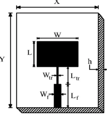
The top view geometry of CRMA is as shown in Fig. 1. This CRMA consists of a radiating patch of width „W‟ and
area X × Y with thickness h= 0.16 cm and a relative permittivity of 4.2 is used. The simulation performances are done by using commercial Ansoft HFSS software package.
Fig-1: Top view geometry of CRMA
Fig-2: Top view geometry of RMA
Figure 2 shows the top view geometry of proposed RMA which is realized from CRMA by using a single 50Ω microstripline feed of length (Lg+g) = 2.77cm. This length of feed line is 28.8% shorter than the length (Lf+ Ltr) of
microstripline used for CRMA as shown in Fig. 1 which makes RMA compact in its size and simplifies the design structure. The microstripline of RMA is connected at the centre along the width of the rectangular patch. A continuous copper ground plane of heightLg = 2.5cm is placed below the microstripline feed on the bottom layer of the
substrate.The distance between the radiating patch and the partial ground plane is g = 0.27 cm. The proposed RMA is dependent on the two important parameters such as height of partial ground plane Lgand feed distance „g‟. By
Table -1: Design parameters of the proposed antennas
Antenna Parameters W L Wtr Ltr Wf Lf Lg h g Dimensions in cm 2.66 2.04 0.06 1.09 0.32 2.18 2.5 0.16 0.27
III.RESULT AND DISCUSSIONS
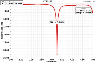
The variation of return loss versus frequency of CRMA is as shown in Fig. 3. From this figure, it is clear that, the impedance bandwidth over return loss less than -10 dB simulated using commercial electromagnetic simulation software Ansoft HFSS, the CRMA resonates at 3.25 GHz of frequency which is close to the design frequency of 3.5 GHzwhich justifies the design of CRMA. From Fig. 3, the impedance bandwidth is calculated using the equation,
100%
fH fL BW
fc
(1)
where, fL and fH are the lower and upper cut of frequencies of the band, respectively, when its return loss reaches -10 dB and fcis the centre frequency betweenfH and fL.The impedance bandwidth of CRMA is found to be BW1 = 3.08%.
Fig. 3 Variation of return loss versus frequency of CRMA
When CRMA is modified as RMA, the antenna operates from 1.54 GHz to 4.62 GHz. This means that, the antenna operates for a wide band of frequencies BW2 which is quite large compared to the operating band of BW1. The
magnitude of impedance bandwidths BW2 is found to be 100%. Hence 3.08% of impedance bandwidth of CRMA has
been enhanced to 100 % by constructing RMA. Further from Fig. 4 it is clear that, the lower cut off frequency of RMA is 1.54 GHz. By comparing the lower cut off frequency of CRMA shown in Fig. 3 which is at 3.20 GHz,the RMA also shows the property of virtual size reduction which is 51.87%. The peak gain of CRMA and RMA are measured in their operating bands BW1 and BW2, are found to be 2.10 dB and 7.08 dBrespectively. Hence by constructing RMA gain can
be enhanced by 3.35 times more than the peak gain of CRMA.
1.00 1.50 2.00 2.50 3.00 3.50 4.00 4.50 5.00
Freq [GHz] -35.00
-30.00 -25.00 -20.00 -15.00 -10.00 -5.00 0.00
R
et
u
rn
L
o
ss
[
d
B]
HFSSDesign1
XY Plot 12 ANSOFT
m1
BW1= 3.08%
Curve Info
dB(S(1,1)) Setup5 : Sweep
Name X Y
-30.00 -20.00 -10.00 90 60 30 0 -30 -60 -90 -120 -150 -180 150 120 HFSSDesign1
Radiation Pattern 7 ANSOFT
Curve Info
dB(GainTotal) Setup2 : Sweep Freq='1.8GHz' Phi='0deg'
dB(GainTotal) Setup2 : Sweep Freq='1.8GHz' Phi='90deg' -35.00 -20.00 -5.00 90 60 30 0 -30 -60 -90 -120 -150 -180 150 120 HFSSDesign1
Radiation Pattern 8 ANSOFT
Curve Info
dB(GainTotal) Setup2 : Sweep Freq='4GHz' Phi='0deg'
dB(GainTotal) Setup2 : Sweep Freq='4GHz' Phi='90deg'
Fig. 4 Variation of return loss versus frequency of RMA
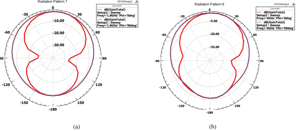
The typical co-polar and cross-polar radiation pattern of RMA is measured in its operating band i.e. at 1.88 GHz (m1)
and 4 GHz (m2) which are shown in Fig. 5(a)-5(b) respectively. From Fig. 5 it is clear that, the patternsarenearly
omnidirectional in nature.
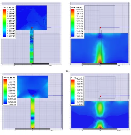
Figure 6(a) and 6(b) shows the top and ground plane surface current distributions of RMA which are observed at the typical frequencies of 1.88 GHz and 4 GHz respectively. Fromthese figures it is seen that, the current distribution towards the edge point of the microstriplinefeed on top surface and uniform current distribution is observed at the ground plane surface of the antenna causing wideband operation.
(a) (b)
Fig. 5 Radiation pattern of RMA measured at 1.88 GHz and 4 GHz
1.00 1.50 2.00 2.50 3.00 3.50 4.00 4.50 5.00
Frequency [GHz] -25.00 -20.00 -15.00 -10.00 -5.00 0.00 R et u rn L o ss [ d B] HFSSDesign1
XY Plot 7 ANSOFT
m2 m1
BW2= 100%
Curve Info
dB(S(1,1)) Setup2 : Sweep
Name X Y
(a)
(b)
Fig. 6 Current distribution of RMA measured on top and ground plane surfaces at1.88 GHz and 4 GHz
IV.CONCLUSION
REFERENCES
1. Constantine A. Balanis, “Antenna theory analysis and design,” John Wiley, New York, 1997. 2. J. Bahl and P. Bharatia. “Microstrip antennas,” Dedham, MA: Artech House, New Delhi, 1981.
3. K. P. Ray, P. V. Anob, R. Kapur, and G. Kumar, “Broadband planar rectangular monopole antennas,” Microwave and Optical Technology Letters, vol. 28, no. 1, pp. 55–59, 2001.
4. N. P. Agrawall, G. Kumar, and K. P. Ray, “Wide-band planar monopole antennas,” IEEE Transactions on Antennas and Propagation, vol. 46, no. 2, pp. 294–295, 1998.
5. K. P. Ray and Y. Ranga, “Ultra-wideband printed modified triangular monopole antenna,” Electronics Letters, vol. 42, no. 19, pp. 1081–1082, 2006.
6. H. K. Kan. Waterhouse. A.Y. J. Lee and Pavlickovski “Dual frequency stacked shorted patch antenna,” Electron let.., vol.41, no.11, pp. 624-626, 2005.
7. K. G. Thomas and M. Sreenivasan,”Compact triple band antenna for WLAN, WiMAX applications,” Electron lett.,vol.45, no.16, pp.811-813, 2009.
8. K. P. Ray, “Design Aspects of Printed Monopole Antennas for Ultra-Wide Band Applications”, International Journal of Antennas and Propagation, Hindawi Publishing Corporation, vol. 2008, pp.1-8, 2008.
9. K. L. Wong, Compact and Broadband Microstrip Antennas. New York, NY: John Wiley and Sons Inc., 2002.
10. Johnson, J. M. and Y. Rahmat-Samii, “The Tab Monopole,” IEEE Trans. Ant. Prop., vol. AP- 45,no. 1, pp. 187-188, Jan. 1997.
BIOGRAPHY
Kalpana Chikatwar received her M. Tech degree in the field of Digital Electronics and Advanced Communication from NITK Surathkal, Mangalore, Karnataka in the year 2006. She is currently working as Associate Professor in E&CE Dept., BKIT Bhalki. Her field of research interest includes Microwave antennas and Advanced wireless communication.
Boya Satyanarayana received his M.Sc and M.Phil degrees in Applied Electronics from the Department of Applied Electronics, Gulbarga University,Gulbarga in the year 2011 and 2013 respectively. Presently he is pursuing Ph.D degree under the guidance of Dr. S. N. Mulgi, Professor in the Department of P. G. Studies and Research in Applied Electronics, Gulbarga University, Gulbarga.