ISSN (Print) : 2320 – 3765 ISSN (Online): 2278 – 8875
I
nternational
J
ournal of
A
dvanced
R
esearch in
E
lectrical,
E
lectronics and
I
nstrumentation
E
ngineering
(An ISO 3297: 2007 Certified Organization)
Website: www.ijareeie.com
Vol. 6, Issue 2, February 2017
A OFDM in LTE Using Different Modulation
Techniques with BER Analysis Based On
Wavelet and Conventional
Neelapuram Shamiullah1, A.Asha2
M.Tech, Dept. of ECE, Global College of Engineering and Technology, Chinnamachupalli, Kadapa, India1
Associate Professor, Dept. of ECE, Global College of Engineering and Technology, Chinnamachupalli, Kadapa, India2
ABSTRACT: Orthogonal Frequency Division Multiplexing (OFDM) and Multiple Input and Multiple Output (MIMO) are two main techniques employed in 4th Generation Long Term Evolution (LTE). In OFDM multiple carriers are used and it provides higher level of spectral efficiency as compared to Frequency Division Multiplexing (FDM). In OFDM because of loss of orthogonality between the subcarriers there is intercarrier interference (ICI) and intersymbol interference (ISI) and to overcome this problem use of cyclic prefixing (CP) is required, which uses 20% of available bandwidth. Wavelet based OFDM provides good orthogonality and with its use Bit Error Rate (BER) is improved. Wavelet based system does not require cyclic prefix, so spectrum efficiency is increased. It is proposed to use wavelet based OFDM at the place of Discrete Fourier Transform (DFT) based OFDM in LTE. We have compared the BER performance of wavelets and DFT based OFDM.
KEYWORDS: LTE; OFDM; DFT; Wavelet; BER.
I. INTRODUCTION
The revolution of wireless communications certainly was one of the most extraordinary Changes underlying our contemporary world although we may not realize it, everyday our lives are profoundly affected by the use of radio waves. Radio and television transmissions, radio-controlled devices, mobile telephones, satellite communications, and radar and systems of radio navigation are all examples of wireless communications happening around us. However, less than a hundred years ago, none of these existed, while the telegraph and telephone were most common for communication, which required direct wire connection between two places
There mark able advancement in communication of today is the result of an Italian scientist, Gugliemo Marconi, as he began experiments using radio waves for communication in 1895. These invisible transmittable waves traveled in air, and since the receiving and transmitting equipment was not connected by wires, the method of communication used was then recognized as wireless communication. Marconi's first success was in 1897, as he Demonstrated radio's ability to provide continuous contact with ships sailing the English channel. By 1920,radio circled the globe and the first radio transmitter was developed and broadcasted programs for the public. Later, the idea of the radio was adopted by Television, radar and communication systems, due to the advancement in electronics Equipment and enabled radio waves to be sent over greater distances
ISSN (Print) : 2320 – 3765 ISSN (Online): 2278 – 8875
I
nternational
J
ournal of
A
dvanced
R
esearch in
E
lectrical,
E
lectronics and
I
nstrumentation
E
ngineering
(An ISO 3297: 2007 Certified Organization)
Website: www.ijareeie.com
Vol. 6, Issue 2, February 2017
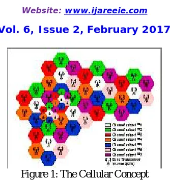
Figure 1: The Cellular Concept
In Figure above, each colored cell is viewed as the (approximate) coverage area of a particular land site. Each cell uses a distinct set of frequencies (channels) and is shown by the difference in color between cells. However, cells that are far enough a part to avoid co-channel interference can reuse the same channel set. In the cellular concept, a mobile user is allowed mobility as a call is "handed off" from one cell to another as the user leaves one cell and enters another. The AMPS cellular system was very popular. However, with the gigantic increase in Subscribers in order of million each year, the AMPS cellular systems began to over loading capacity and became incapable of delivering sufficient air time to reach user .To overcome the problem, more effective multiple access techniques were invented.
II. CODE DIVISION MULTIPLE ACCESS
CDMA system is a multi-user spread spectrum system that eliminates the frequency reuse problem in cellular systems. Unlike TDMA and FDMA systems, where user signals never overlap in either the time or the frequency domains, respectively, a CDMA system allows transmissions at the same time while using the same frequency. For example, in the first widespread commercial CDMA system, The mechanism separating the users in a CDMA system consists of assigning a unique code that modulates the signal from each user; the number of unique codes in a CDMA link is equal to the number of active users. The code modulating the user’s signal is also called a spreading code, spreading sequence, or chip sequence.
Transmitter
The transmitter interoperations comprise of convolution encoding and repetition, block interleaving, long PN sequence, data scrambling, Walsh coding and quadrature modulation.
The Convolution encoder performs error-control coding by encoding the incoming bit stream information. This allows error correction at the receiver, and hence improves communication reliability
In CDMA transmitter, a R =1/2K=9 convolution encoder is deployed. R=1/2 Means the encoder produces 2 code bits for every incoming data information bit , and K=9 Means the encoder has a constraint length of 9; it's a 9 stage shift register. . A diagram of the Convolution encoder is shown in Figure .
Figure 2: Rate1/2 ConvolutionalEncoderforRateset2
Each code bit, 0C and C 1 as shown in Figure 2 is produced according to the two specified generating polynomials g 0 and g 1,which perform modulo-2 addition with the value of specific stages of the shift register.
ISSN (Print) : 2320 – 3765 ISSN (Online): 2278 – 8875
I
nternational
J
ournal of
A
dvanced
R
esearch in
E
lectrical,
E
lectronics and
I
nstrumentation
E
ngineering
(An ISO 3297: 2007 Certified Organization)
Website: www.ijareeie.com
Vol. 6, Issue 2, February 2017
G1(x)=x^9+x^5+x^4+x^3+x^1
As an illustration, 0C is calculated by performing modulo addition to the value in stage1,3,4,5,6,8,and 9 of the shift register as specified by the generator polynomial ;
Then, before the encoded data can be fed into the block interleaver, which is fixed at 19.2kbps, the encoded data may have to be repeated, depending on the original data input rate into the convolution encoder. For example, if the data input rate to the convolution encoderwasat4800kbps,the data would have to berepeated2timestoachieve19.2kbpsbefore inputting to the block interleaver.
Receiver:
The CDMA standard describes the processing performed in the terminal receiver as being complementary to those of the base station modulation processes on the Forward CDMA Channel".
The demodulation processing that the terminal receiver architecture must perform includes Rake receiver combining (IQ demodulation and maximal combining), Walsh decoding, long PN sequence, data descrambling, block-de interleaving, and Viterbi-decoding. These operations all act to reverse the operation of one of the Corresponding components in the transmitter.
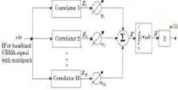
A diagrammatic representation of the Rake Receiver is depicted in the figure
Figure 3: CDMA receiver demodulation process.
RAKE Receiver Combining:
The RAKE receiver essentially acts to reverse the multi path distortion effects of the channel, and in practice, a3 finger Rake receiver is used, as it is economical and provides acceptable signal reception quality in a multi path environment. The structure of the Rake receiver is illustrated in Figure.
Figure 4: A diagrammatic representation of an M-arms rake receiver
III. ORTHOGONAL FREQUENCY DIVISION MULTIPLEXING
Orthogonal Frequency Division Multiplexing (OFDM) has been attracting substantial attention due to its excellent performance under severe channel condition. The rapidly growing application of OFDM includes Wi-MAX, DVB/DAB and 4G wireless systems.
ISSN (Print) : 2320 – 3765 ISSN (Online): 2278 – 8875
I
nternational
J
ournal of
A
dvanced
R
esearch in
E
lectrical,
E
lectronics and
I
nstrumentation
E
ngineering
(An ISO 3297: 2007 Certified Organization)
Website: www.ijareeie.com
Vol. 6, Issue 2, February 2017
of implementing it has many complexities. So, it is a fully software project. OFDM depends on Orthogonality principle. Orthogonality means, it allows the sub carriers, which are orthogonal to each other, meaning that cross talk between co-channels is eliminated and inter-carrier guard bands are not required. This greatly simplifies the design of both the transmitter and receiver, unlike conventional FDM; a separate filter for each sub channel is not required.
Orthogonal Frequency Division Multiplexing (OFDM) is a digital multi carrier modulation scheme, which uses a large number of closely spaced orthogonal sub-carriers. A single stream of data is split into parallel streams each of which is coded and modulated on to a subcarrier, a term commonly used in OFDM systems. Each sub-carrier is modulated with a conventional modulation scheme (such as quadrature amplitude modulation) at a low symbol rate, maintaining data rates similar to conventional single carrier modulation schemes in the same bandwidth. Thus the high bit rates seen before on a single carrier is reduced to lower bit rates on the subcarrier.
Orthogonal Frequency Division Multiplexing (OFDM) is a multicarrier transmission technique, which divides the available spectrum into many carriers, each one being modulated by a low rate data stream. OFDM is similar to FDMA in that the multiple user access is achieved by subdividing the available bandwidth into multiple channels that are then allocated to users. However, OFDM uses the spectrum much more efficiently by spacing the channels much closer together. This is achieved by making all the carriers orthogonal to one another, preventing interference between the closely spaced carriers.
Coded Orthogonal Frequency Division Multiplexing (COFDM) is the same as OFDM except that forward error correction is applied to the signal before transmission. This is to overcome errors in the transmission due to lost carriers from frequency selective fading, channel noise and other propagation effects. For this discussion the terms OFDM and COFDM are used interchangeably, as the main focus of this thesis is on OFDM, but it is assumed that any practical system will use forward error correction, thus would be COFDM.
In FDMA each user is typically allocated a single channel, which is used to transmit all the user information. The bandwidth of each channel is typically 10 kHz-30 kHz for voice communications. However, the minimum required bandwidth for speech is only 3 kHz. The allocated bandwidth is made wider than the minimum amount required preventing channels from interfering with one another. This extra bandwidth is to allow for signals from neighboring channels to be filtered out, and to allow for any drift in the center frequency of the transmitter or receiver. In a typical system up to 50% of the total spectrum is wasted due to the extra spacing between channels.
This problem becomes worse as the channel bandwidth becomes narrower, and the frequency band increases. Most digital phone systems use vocoders to compress the digitized speech. This allows for an increased system capacity due to a reduction in the bandwidth required for each user.
Current vocoders require a data rate somewhere between 4- 13kbps, with depending on the quality of the sound and the type used. Thus each user only requires a minimum bandwidth of somewhere between 2-7 kHz, using QPSK modulation. However, simple FDMA does not handle such narrow bandwidths very efficiently. TDMA partly overcomes this problem by using wider bandwidth channels, which are used by several users. Multiple users access the same channel by transmitting in their data in time slots. Thus, many low data rate users can be combined together to transmit in a single channel, which has a bandwidth sufficient so that the spectrum can be used efficiently.
As for mentioned, OFDM is a special form of MCM and the OFDM time domain waveforms are chosen such that mutual orthogonality is ensured even though sub-carrier spectra may over-lap. With respect to OFDM, it can be stated that orthogonality is an implication of a definite and fixed relationship between all carriers in the collection. It means that each carrier is positioned such that it occurs at the zero energy frequency point of all other carriers. The since function, illustrated in Fig. 5 exhibits this property and it is used as a carrier in an OFDM system.
ISSN (Print) : 2320 – 3765 ISSN (Online): 2278 – 8875
I
nternational
J
ournal of
A
dvanced
R
esearch in
E
lectrical,
E
lectronics and
I
nstrumentation
E
ngineering
(An ISO 3297: 2007 Certified Organization)
Website: www.ijareeie.com
Vol. 6, Issue 2, February 2017
It means that each carrier is positioned such that it occurs at the zero energy frequency point of all other carriers. The since function, illustrated in Fig. 2.1 exhibits this property and it is used as a carrier in an OFDM system.
Figure 5: OFDM sub carriers in the frequency domain
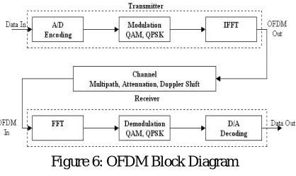
To generate OFDM successfully the relationship between all the carriers must be carefully controlled to maintain the orthogonality of the carriers. For this reason, OFDM is generated by firstly choosing the spectrum required, based on the input data, and modulation scheme used. Each carrier to be produced is assigned some data to transmit. The required amplitude and phase of the carrier is then calculated based on the modulation scheme (typically differential BPSK, QPSK, or QAM). The required spectrum is then converted back to its time domain signal using an Inverse Fourier Transform. In most applications, an Inverse Fast Fourier Transform (IFFT) is used. The IFFT performs the transformation very efficiently, and provides a simple way of ensuring the carrier signals produced are orthogonal. The IFFT performs the reverse process, transforming a spectrum (amplitude and phase of each component) into a time domain signal. An IFFT converts a number of complex data points, of length, which is a power of 2, into the time domain signal of the same number of points. Each data point in frequency spectrum used for an FFT or IFFT is called a bin. The orthogonal carriers required for the OFDM signal can be easily generated by setting the amplitude and phase of each bin, then performing the IFFT. Since each bin of an IFFT corresponds to the amplitude and phase of a set of orthogonal sinusoids, the reverse process guarantees that the carriers generated are orthogonal.
Figure 6: OFDM Block Diagram
IV. INTRODUCTION TO WAVELETS
ISSN (Print) : 2320 – 3765 ISSN (Online): 2278 – 8875
I
nternational
J
ournal of
A
dvanced
R
esearch in
E
lectrical,
E
lectronics and
I
nstrumentation
E
ngineering
(An ISO 3297: 2007 Certified Organization)
Website: www.ijareeie.com
Vol. 6, Issue 2, February 2017
Figure 7: Orthogonal Frequency Division Multiplexing
Wavelet transform is capable of providing the time and frequency information simultaneously, hence giving a time-frequency representation of the signal.
How wavelet transform works is completely a different fun story, and should be explained after short time Fourier Transform (STFT) . The WT was developed as an alternative to the STFT. The STFT will be explained in great detail in the second part of this tutorial. It suffices at this time to say that he WT was developed to overcome some resolution related problems of the STFT, as explained in Part II.
To make a real long story short, we pass the time-domain signal from various high pass and low pass filters, which filter out either high frequency or low frequency portions of the signal. This procedure is repeated, every time some portion of the signal corresponding to some frequencies being removed from the signal.
Here is how this works: Suppose we have a signal which has frequencies up to 1000 Hz. In the first stage we split up the signal in to two parts by passing the signal from a high pass and a low pass filter (filters should satisfy some certain conditions, so-called admissibility condition) which results in two different versions of the same signal: portion of the signal corresponding to 0-500 Hz (low pass portion), and 500-1000 Hz (high pass portion).
ISSN (Print) : 2320 – 3765 ISSN (Online): 2278 – 8875
I
nternational
J
ournal of
A
dvanced
R
esearch in
E
lectrical,
E
lectronics and
I
nstrumentation
E
ngineering
(An ISO 3297: 2007 Certified Organization)
Website: www.ijareeie.com
Vol. 6, Issue 2, February 2017
Figure 8: Continuous Wavelet Transform
V. RESULTS
PERFORMANCE OF OFDM USING FFT FOR DIFFERENT CHANNELS
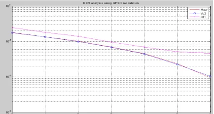
Figure 9: PERFORMANCE OF OFDM USING FFT FOR DIFFERENT CHANNELS
ISSN (Print) : 2320 – 3765 ISSN (Online): 2278 – 8875
I
nternational
J
ournal of
A
dvanced
R
esearch in
E
lectrical,
E
lectronics and
I
nstrumentation
E
ngineering
(An ISO 3297: 2007 Certified Organization)
Website: www.ijareeie.com
Vol. 6, Issue 2, February 2017
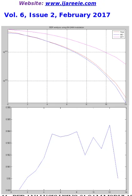
Figure 11: BER ANALYSIS USING 64 QAM MODULATION
Figure 12: BER VS SNR USING 16 QAM
VI. CONCLUSION
ISSN (Print) : 2320 – 3765 ISSN (Online): 2278 – 8875
I
nternational
J
ournal of
A
dvanced
R
esearch in
E
lectrical,
E
lectronics and
I
nstrumentation
E
ngineering
(An ISO 3297: 2007 Certified Organization)
Website: www.ijareeie.com
Vol. 6, Issue 2, February 2017
REFERENCES
[1] A. Ian F., G. David M., R. Elias Chavarria, “The evolution to 4G cellular systems: LTE-advanced”, Physical communication, Elsevier, vol. 3, no. 4, pp. 217-244, Dec. 2010.
[2] B. John A. C., “Multicarrier modulation for data transmission: an idea whose time has come”, IEEE Communications magazine, vol. 28, no. 5, pp. 5-14, May 1990.
[3] L. Jun, T. Tjeng Thiang, F. Adachi, H. Cheng Li, “BER performance of OFDM-MDPSK system in frequency selective rician fading and diversity reception” IEEE Transactions on Vehicular Technology, vol. 49, no. 4, pp. 1216-1225, July 2000.
[4] K. Abbas Hasan, M. Waleed A., N. Saad, “The performance of multiwavelets based OFDM system under different channel conditions”, Digital signal processing, Elsevier, vol. 20, no. 2, pp. 472-482, March 2010.
[5] K. Volkan, K. Oguz, “Alamouti coded wavelet based OFDM for multipath fading channels”, IEEE Wireless telecommunications symposium, pp.1-5, April 2009.
[6] G. Mahesh Kumar, S. Tiwari, “Performance evaluation of conventional and wavelet based OFDM system”, International journal of electronics and communications, Elsevier, vol. 67, no. 4, pp. 348-354, April 2013.
[7] J. Antony, M. Petri, “Wavelet packet modulation for wireless communication”, Wireless communication & mobile computing journal, vol. 5, no. 2, pp. 1-18, March 2005.
[8] L. Madan Kumar, N. Homayoun, “A review of wavelets for digital wireless communication”, Wireless personal communications, Kluwer academic publishers- Plenum publishers, vol. 37, no. 3-4, pp. 387-420, May 2006.
[9] Broughton SA, Bryan K. Discrete Fourier analysis and wavelets. New Jersey, John Wiley, 2009.
BIOGRAPHY
Neelapuram Shamiullah received his B.Tech degree from Chaitanya Bharati Instittue of Technology, Proddutur, Kadapa Dt. (Affiliated to JNTUA Anantapur) Department of ECE. He is pursuing M.Tech in Global College of Engineering and Technology. Chinnamachupalli, Chennur, Andhra Pradesh 516162.