Multimedia Data Hiding and Authentication
via Halftoning and Coordinate Projection
Chai Wah Wu
IBM Research Division, Thomas J. Watson Research Center, P.O. Box 218, Yorktown Heights, NY 10598, USA Email: [email protected]
Received 4 May 2001 and in revised form 14 September 2001
We present image data hiding and authentication schemes based on halftoning and coordinate projection. The proposed data hiding scheme can embed images of the same size and similar bit depth into the cover image and robustness against compression is demonstrated. The image authentication scheme is based on the data hiding scheme and can detect, localize, and repair the tampered area of the image. Furthermore, the self-repairing feature of the authentication scheme has a hologram-like quality; any portion of the image can be used to reconstruct the entire image, with a greater quality of reconstruction as the portion size increases.
Keywords and phrases:data hiding, authentication, tamper detection, self-repairing images, error diffusion, digital halftoning, coordinate projection.
1. INTRODUCTION
Recently, there has been much interest in multimedia data hiding, where information is imperceptibly embedded into multimedia content such as images and music [1]. The em-bedded data can contain ownership identification, tracking information, recipient information, time stamps, authentica-tion data, and other informaauthentica-tion useful for various applica-tions such as copyright protection, data integrity verification, verification of origin of data, recipient tracking, and so forth. In many applications, the main requirement is that the em-bedding changes the multimedia content imperceptibly. In this paper, we describe a system of embedding images into a source image by using digital halftoning algorithms and co-ordinate projections. In particular, we show how an entire image can be embedded into another source image and illus-trate design requirements for robustness against distortions such as JPEG compression. The proposed embedding method can also be used in an image authentication scheme, where changes to an image can be detected, localized, and repaired. The repair operation reconstructs the original source image using information distributed over the entire image. In this sense it exhibits hologram-like properties; any portion of the image can be used to reconstruct the entire image. The larger the portion used for reconstruction, the higher the fidelity of the reconstructed image.
2. DATA EMBEDDING AND EXTRACTION ALGORITHMS
We consider images represented as matrices of vectors. For example, an imageMis represented as ann×mmatrix of
d-dimensional vectors. The(i, j)th entry ofM, denoted as
M(i, j), is called the(i, j)th pixel ofM. Each pixelM(i, j)is ad-dimensional vector, whereddenotes the dimension of the color space, that is,d= 1for a grayscale image,d= 3 for an image in RGB or LAB color space andd =4for an image in CMYK space. We assume that each pixel is in the
d-dimensional setSd. In many current image formats,Sd= {0,1, . . . ,255}disdbytes of data. In some applications, we also representMasdmatrices of scalars. For instance, a color image in RGB space can be considered as3grayscale images by separating the image into its separate color planes.
Given a source image M0 and additional images M1, M2, . . . , Mk, the proposed data hiding method consists of two algorithms. The data embedding algorithm embeds
M1, M2, . . . , Mkimperceptibly into the source image (or cover image)M0resulting in amodified source imageM0. The data extraction algorithm extracts the imagesM1, M2, . . . , Mkfrom M0.
We first give a general description of these algorithms. A set C of extended colors is first chosen. Each member of this set C is a (k+1)-tuple of d-dimensional vectors. For a member D ∈ C, each of the k+1 d-dimensional vectors of D is called a coordinate of D. For example, for
D = (c1, c2, . . . , ck+1) where each ci is a d-dimensional vector, the first,second, . . . , (k+1)th coordinates of D are
c1, c2, . . . , ck+1, respectively. The setCis chosen such that it satisfies the following condition: for eachjin the setSd, there
Start
End
PickExoutwhereExout(i, j)is an element ofC andExoutlooks like(M0, M1, . . . , Mk).
Set modified source imageM0
as the first coordinates ofExout.
Apply optional postprocessing toM0.
(a)
Figure1: (a) Flowchart of data embedding algorithm. (b) Flowchart of data extracting algorithm.
other words,Cis of the form(x, f (x)),x∈U⊂Sdwheref
is a map fromSdinto(Sd)k. In some applications we require
additionally thatCis of the same size asSd. This means that
for eachjin the setSd, there exists exactly one member ofC
such that the first coordinate isjand the projection ofCinto its first coordinates is a bijectionpCfromContoSd. In this
case,U=Sd.
We embed the imagesM1, . . . , MkintoM0as follows: an extended output imageExoutis chosen as a matrix of elements
of C. Then the modified source image M0 is generated by taking the first coordinate of the entries of Exout, that is, M0(i, j)is the first coordinate ofExout(i, j).
If the size ofCis strictly less than the size ofSd, in general M0is different fromM0and the following optional postpro-cessing step can be implemented to changeM0 in order to reduce the difference betweenM0andM0. For eachM0(i, j), letT (i, j)be the set of points inSdwhich are strictly closer
toM0(i, j)than to any other first coordinates of elements of C. Then pick the newM0(i, j)as the element ofT (i, j)which is closest toM0(i, j). Note that if the size ofCis equal to the size ofSd, thenT (i, j)consists of a single elementM0(i, j) and the postprocessing step does not changeM0at all.
To extract the embedded images fromM0, the following algorithm is used. For each of the pixelsM0(i, j)ofM0, find the element c(i, j)inC whose first coordinate is closest to
M0(i, j).1 Then generate the reconstructed embedded im-agesM1, M2, . . . , Mkby settingMu(i, j) equal to the(u+1)th
coordinate of c(i, j),u =1, . . . , k. It is clear that the post-processing step does not affect the extraction ofM1, . . . , Mk.
Flowcharts of these two algorithms are shown in Figure 1. To illustrate these ideas, consider the following simple ex-ample of embedding a sequenceM1 into another sequence M0(i.e.,k=1). LetC= {(1,2), (4,4), (7,2), (10,8)},M0= equal toM0. Applying the data extracting algorithm toM0, we obtainM1=(4,8,2,2,4)which is similar toM1.
It is clear that M0, M1, M2, . . . , Mk form the
coordi-nates of Exout. Since Exout consists of elements of C and (M0, M1, . . . , Mk)consist of elements of(Sd)k+1, and in gen-eralCis a small subset of(Sd)k+1, it follows that in general Miwill not be the same asMi. The goal is to pickExout
appro-priately in order to ensure that the imagesM0, M1, M2, . . . , Mk
look likeM0, M1, M2, . . . , Mk, respectively. To accomplish this, the problem is recast as a halftoning problem and a suitable halftoning algorithm is used to pick the entries ofExout.
We now describe the proposed algorithms in more de-tail. Given a source image M0 and k auxiliary images M1, M2, . . . , Mk, the goal is to create a modified imageM0 which looks like the source image M0 such that images M1, . . . , Mk can be extracted fromM0 andM1, . . . , Mk look
like M1, M2, . . . , Mk, respectively. We say that the images M1, M2, . . . , Mk are embedded into the modified imageM0. We denoteMu(i, j)as the (i, j)th pixel of imageMu. Each pixel ofMuis a scalar or a vector, depending on whether the image is a grayscale image or a color image. Furthermore, the pixels of each imageMucan be represented in different color spaces, that is,M1 can be in RGB space,M2 can be in LAB space, and so forth.
In a halftoning problem, given an input imageI, the goal is to generate a halftone imageH, where each pixel ofHis
1If the bijectionp
from a restricted set of output colors, such that H“looks” like I when viewed at the proper distance. Given the algo-rithm to extract M1, . . . , Mk as described earlier, the
prob-lem of choosingExoutcan be recast as a halftoning problem.
Consider the imageX where the(i, j)th pixel is the vector
(M0(i, j), M1(i, j), M2(i, j), . . . , Mk(i, j)). The set of possi-ble output colors isC. The corresponding halftoning prob-lem is to generate a halftone image where every pixel is an element ofCsuch that the halftone image looks likeX. Then the solution obtained by a halftoning algorithm which solves this halftoning problem is used as the extended output image
Exout. Some halftoning algorithms we use for this purpose
will be vector error diffusion and local iterative methods. How does one quantify the requirement that the halftone image “looks” like the original image? One commonly used way is to model the human visual system (HVS) as a linear low-pass filter. The imageA“looks” like imageBifL(A−B) is small, whereLdenotes the linear low-pass operator of the human visual system. In our case, the halftoning problem becomes the following optimization problem: find the output imageExoutconsisting of pixels from the setCsuch that
k
u=0
vuLuExoutu −Mupu (1)
is minimized whereExoutu denotes the image extracted from Exout by taking the(u+1)th coordinates of each pixel of Exout. The exponentspu are generally chosen to be2. The
weightsvucorrespond to different weighting factors for the different images. For example, if the closeness between the modified source imageM0and the original source imageM0 is important, then the weightv0should be larger than the other weights.Lu is the linear low-pass filter for the image
Mu. When the images Mu are all in the same color space,
Lu=Lis the same for allu. We will discuss a case later where the images have different modalities (some of theMu’s are not even images) andLu is different for differentu’s. Examples of the linear filterLcan be found in Näsänen [2] and Sullivan et al. [3].
Consider the use of vector error diffusion [4] as the halftoning method to minimize (1). We pick the(i, j)th pixel of the extended output imageExout(i, j)as the member ofC
which is the closest to the(k+1)-tuple
˜
M0(i, j),M˜1(i, j), . . . ,Mk(i, j)˜ . (2)
The notion of closeness can be the Euclidean norm or a weighted Euclidean norm, with different weights for the dif-ferent imagesM˜0, . . . ,Mk˜ , for example, the distance between a
Mu(i, j)is the modified input forMuat location(i, j)and is defined as
˜
Mu(i, j)=Mu(i, j)+ x,y
wu(x, y)eu(i−x, j−y), (4)
wherewu are the error diffusion weights corresponding to
Mu. See [5] for the design of error diffusion weights appro-priate for the chosen human visual system model.
AfterExout(i, j)is constructed, the first coordinate of the (k+1)-tupleExout(i, j)will be used to form the(i, j)th pixel
of the modified source imageM0. Pseudocode of this algo-rithm is shown in Algoalgo-rithm 1. We have omitted the optional postprocessing step in this description as it is the same as be-fore and this step is not needed if the size ofCis equal to the size ofSd.
In certain applications, some of the embedded data
M1, M2, . . . , Mk are not images, but rather information bits containing the name of the owner, the date, compressed im-age data, and so forth. Without loss of generality, we assume thatMu(u≥q)are this type of embedded data. In this case these recovered data Mu should match exactly the
embed-ded data Mu foru ≥ q. A necessary condition for this to happen is that each pixel of (Mq, . . . , Mk) is equal to the
q+1, . . . , (k+1)th coordinates of some element ofC. To en-sure thatMu matchesMu,vuis set to be very large andLuis
set to be the impulse delta function (all-pass filter) foru≥q. This will make sure that the error term of (1) corresponding to dataMuisvuExoutu −Mupforu≥qwhich is minimized
by choosingMu =Exoutu =Muforu≥q. In the vector error
diffusion algorithm this is accomplished by setting the error diffusion weightswu =0foru≥q. This makesMu˜ =Mu foru≥q, and thusExuout(i, j)is chosen to be the closest to Mu(i, j)which is equal to settingExoutu (i, j)=Mu(i, j)for u ≥ qby the necessary condition above. Thus for theuth image(u≥q), error diffusion is not used and the image is simply quantized.
In particular, consider the special caseq = k = 1, and
C =(x, f (x))wherex ∈ ∪Siwith eachSia discrete set of quantization points andfis defined asf (x)=iifx∈Si. If
M1consists of indicesiandL0=L1is the impulse delta func-tion, then the resulting scheme is equivalent to quantization index modulation (QIM) when the information bits are em-bedded into in the space of image pixels [6]. In this case, we get better results by settingL0equal to an HVS low-pass filter and apply halftoning (such as error diffusion) in addition to QIM. For example, in QIM applied to image pixels, each im-age pixel is quantized according to a quantizer indexed by the information bits. If error diffusion is used as the halftoning algorithm, the modified input pixelM˜0(i, j)rather than the image pixelM0(i, j)is quantized by the indexed quantizer.
Another case where error diffusion is not used for the data
For eachi /* For each row*/
For eachj /* For each column*/
For eachu /* For each image*/
˜
Mu(i, j)=Mu(i, j)+
x,ywu(x, y)eu(i−x, j−y)
Endfor
Exout(i, j)=argmin
c∈C
uvu ˜
Mu(k, l)−cup 1/p
/*cuis the(u+1)th coordinate of c*/
(e0(i, j), . . . , ek(i, j))=(M˜0(i, j),M˜1(i, j), . . . ,M˜k(i, j))−Exout(i, j)
Endfor
Endfor
Set modified source imageM0as the first coordinates ofExout.
Algorithm1: Pseudocode of data hiding algorithm using vector error diffusion.
(a) (b)
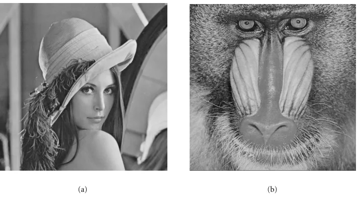
Figure2: (a) Source imageM0. (b) Embedded imageM1.
relationship that error diffusion mandates, for example, when
Muare the DCT coefficients of an image.
3. EXAMPLES
We illustrate the data hiding scheme by considering the case of a grayscale image, that is, the dimension of the color space
das defined earlier is equal to 1. We assume that each pixel in the image is an integer between 0 and 255. Furthermore, assume that we want to embed a single image M1into the source imageM0(i.e.,k=1).
Consider the source imageM0shown in Figure 2a and an auxiliary imageM1shown in Figure 2b. Figure 3a shows the modified source imageM0after embeddingM1. Figure 3b shows the extracted imageM1.
For vector error diffusion, the convex hull of the output color setC should cover as much as possible the space of possible(k+1)-tuples ofd-dimensional vectors [7], or in this
(a) (b)
Figure3: (a) Modified imageM0withM1embedded. (b) Extracted imageM1.
0 50 100 150 200 250
0 50 100 150 200 250
a
f
(a)
(a)
0 50 100 150 200 250
0 50 100 150 200 250
a
f
(a)
(b)
Figure4: Candidates for the setC. (a) Distributed points covering[0,255]2. (b) A relative smooth functionf.
the constraint thatCis of the form(a, f (a)).
As indicated in Section 2 for the general case, the projec-tion ofConto the first coordinate is the set{0,1, . . . ,255}d,
andCcan be thought of as a set of the form(x, f (x))where
fis a function from{0,1, . . . ,255}dinto{0,1, . . . ,255}kd. To cover a large area and be uniformly distributed across
[0,255]2, the functionfthat definesCis generally highly dis-continuous. This implies that small changes in the modified source imageM0result in large changes in the extracted im-ageM1. By using a smoother function forC, this effect can be reduced resulting in more robustness for the extracted image against changes in the modified source image. An example of such a smootherCis shown in Figure 4b. This usually comes at a cost of the convex hull of Ccovering a smaller area of
[0,255]2and the points ofCbeing less distributed. This can result in larger errors in the error diffusion process and gen-eratesM0,M1that are less faithful to the original imagesM0, M1, respectively. One way to avoid large errors is to project the input colors in[0,255]2into the convex hull of C [7]. Note that the range offin Figure 4b consists of 16 discrete values. ThusM1is halftoned intoM1via 4-bit multilevel error diffusion. Actually, the halftoning is somewhat worse due to the constraint of also halftoningM0.
(a) (b)
Figure5: (a) Modified imageM0withM1embedded using the setCin Figure 4b. (b) Extracted imageM1after JPEG compression ofM0.
0 50 100 150 200 250
0 50 100 150 200 250
a
re
verse
(a)
Figure6: The setC=(a,reverse(a))wherereverse(a)isawith the bits reversed.
shown in Figure 5b. We see that distortion has occurred due to the JPEG lossy compression, but the embedded image is still recognizable.
Since the extraction of the embedded data is done on a pixel-by-pixel basis, (part of) the embedded data can still be extracted if the image is cropped or transformed geometri-cally without modifying the pixel values.
In a paper by Knox [8], a system was proposed to embed an image into another image which share some similarities with the above algorithm. In fact, Knox’s approach is simi-lar to a special case of the proposed algorithm with a spe-cific setC. The data embedding and extraction algorithms in Knox’s approach are based on reversing the bits of the pixels. This corresponds to a setCof the form(a,reverse(a))where reverse(a)isawith the bits reversed. This setCis shown in Figure 6. Except for the lower-right and upper-left corners,
this set covers the square[0,255]2rather uniformly. In fact Figure 4a is created from Figure 6 by moving some of the more closely clustered dots to the lower-right and upper-left corners.
One difference between Knox’s approach and the pro-posed algorithm is that in Knox’s algorithm two separate 4-bit multilevel error diffusion algorithms are applied inde-pendently to the two images and therefore the choice of the output colors can be less ideal than the current algorithm where the error diffusion is applied jointly to the two im-ages by considering pairs of pixel values. Furthermore, the current algorithm has the additional flexibility of having dif-ferent weightsvufor the different images.
Another feature of the proposed scheme is the flexibility in which the setCcan be chosen;Ccan be any set of the form
(a, f (a))and the functionfcan be chosen depending on the application and requirements. For instance,fcan be smooth for more robustness, orf can be chosen so the convex hull of C cover a large portion of (Sd)k+1 for small distortion between Mu andMu˜ . Furthermore, the functionf can be one-to-one (as is the case forreverse(a)) or not (as is the case in quantization index modulation).
4. IMAGE AUTHENTICATION SCHEME
For each iteration /* For each iteration*/
For eachi /* For each row*/
For eachj /* For each column*/
For each memberdofC /* Search through all possible members ofC*/
SetExout(i, j)=d
Endfor (iteration) or untilExouthas not changed between two consecutive iterations.
Set modified source imageM0as the first coordinates ofExout.
Algorithm2: Pseudocode of data hiding algorithm using iterative halftoning.
the spatial relationship between the pixels, the inverse per-mutation is applied in the halftoning algorithm to restore the spatial relationship before calculating the error function, that is, the function to minimize is
v0LEx0out−M02+v1LP Exout1 −M02, (5)
whereP Ex1outis the image defined by
P Exout1 (i, j)=Exout1 (P (i, j)). (6)
Since the spatial relation between the pixels inEx0
outand
Ex1
out is now different, a halftoning algorithm such as error
diffusion which relies on a certain order of pixel traversal is not suitable. We will use an isotropic iterative halftoning algorithm instead.
In particular, at each iteration the pixels are traversed in a particular order and for each location (i, j), the pixel
Exout(i, j) is chosen from the setC, such that (5) is
min-imized. This is run through several iterations until a local minimum is reached (i.e., no pixel changes between two it-erations) or the maximum number of iterations is reached. The pseudocode of this algorithm is shown in Algorithm 2.
Because of the permutation, localized changes to the modified source image result in changes to the embedded images which are spread out throughout the image. This is similar to the interleaving techniques used in error correction codes to combat burst errors in, for example, compact disk recordings. The reconstructed embedded image (after inverse permutation) is compared with the modified source image to check whether significant changes have occurred. This op-eration can also localize where such changes have occurred. Furthermore, because the changes are spread out throughout the embedded image, the changes to the embedded image will not be as disruptive visually than if the changes occurred in blocks. This allows the corrupted source image to be repaired
by using the embedded image. This is illustrated in Figures 7, 8, and 9.
In Figure 7a, the modified source imageM0 is corrupted by erasing a portion of the image and adding text and other changes to the image. Next we extract the embedded image
M1 from this corrupted M0. After applying the inverse per-mutation toM1we see that it still resemblesM0, as shown in Figure 7b. In fact, the tampered portions of the image have been recovered to a certain degree. The noise pixels which occur throughout the image correspond to the tampered pix-els in the source image which have been spread out by the permutationP.
Define P M1(i, j) = M1(P (i, j)). By low-pass filtering (M0−P M1)and finding the pixels with relatively large norms, an estimate of where the modification occurs can be found. This is shown in Figure 8a, where the black pixels indicate where the modifications to the source image occurred. This estimate can be further refined by morphological operations to remove small clusters of pixels and fill in small holes.
This estimate can also be used to determine where the embedded image should be recovered. If a pixel is corrupted in the modified source imageM0, then this pixel (after apply-ing the permutation) is not recovered in the embedded image
P M1, but interpolated from other pixels which are not cor-rupted. Using this algorithm with bilinear interpolation re-sults in Figure 8b. We see that much of the noise in Figure 7b has been removed. The residual impulsive noise can be fur-ther removed by means of a3by3median filter (Figure 9).
An alternative algorithm for recovering the source image is as follows. Using the above estimate, for the pixels which were not corrupted in the modified source image, the “re-paired” source image pixels are set to the modified source image pixels. For the corrupted pixels, the “repaired” source pixels are recovered from the embedded image using inter-polation as before.
(a) (b)
Figure7: (a) Embedded imageM0after tampering. (b) Recovered image.
(a) (b)
Figure8: (a) Estimate of where tampering has occurred. (b) Recovered image by interpolating from untampered pixels.
from secret keys. For color images, the size of C can be as large as or larger than2563. This could be too large to imple-ment the halftoning algorithm efficiently. In this case, the color image is split into the color planes, and each color plane is processed independently. In other words, an RGB im-age is considered as3grayscale images which are processed independently.
5. CONCLUSIONS
We have proposed a data hiding scheme which utilizes halftoning algorithms to maintain imperceptibility of em-bedding by minimizing the distortion of the modified source image and of the embedded images. One-to-one coordinate
projection is used to ensure that the embedded images can be extracted. Tradeoff between robustness against minor mod-ifications and embedding distortion can be obtained by a proper choice of the extended color setC. The data hiding scheme can be used in an image authentication scheme where tampering can be detected, localized and reversed.
We have considered the coordinates of elements of the set
Cas values of single pixels. An extension of the algorithm is to consider the case where the coordinates are values of blocks of pixels.
Figure 9: Reconstructed source image after median filtering of Figure 8b.
halftoning can be used to embed data into video streams as a whole.
ACKNOWLEDGEMENT
The author would like to thank the anonymous reviewers for their helpful comments.
REFERENCES
[1] F. A. P. Petitcolas, R. J. Anderson, and M. G. Kuhn, “Information hiding—a survey,” Proceedings of the IEEE, vol. 87, no. 7, pp. 1062–1078, 1999.
[2] R. Näsänen, “Visibility of half-tone dot textures,” IEEE Trans. Systems, Man, and Cybernetics, vol. 14, no. 6, pp. 920–924, 1984. [3] J. Sullivan, L. Ray, and R. Miller, “Design of minimum visual modulation halftone patterns,”IEEE Trans. Systems, Man, and Cybernetics, vol. 21, no. 1, pp. 33–38, 1991.
[4] H. Haneishi, T. Suzuki, N. Shimoyama, and Y. Miyaki, “Color digital halftoning taking colorimetric color reproduction into account,”Journal of Electronic Imaging, vol. 5, pp. 97–106, Jan-uary 1996.
[5] B. W. Kolpatzik and C. A. Bouman, “Optimized error diffusion for high quality image display,” Journal of Electronic Imaging, vol. 1, no. 3, pp. 277–292, 1992.
[6] B. Chen and G. W. Wornell, “Quantization index modulation: a class of provably good methods for digital watermarking and in-formation embedding,”IEEE Transactions on Information The-ory, vol. 47, no. 4, pp. 1423–1443, 2001.
[7] R. Adler, B. Kitchens, M. Martens, A. Nogueira, C. Tresser, and C. W. Wu, “Error bounds for error diffusion and other math-ematical problems arising in digital halftoning,” inIS&T/SPIE Conference on Color Imaging: Device-Independent Color, Color Hardcopy, and Graphic Arts V, Proceedings of SPIE, vol. 3963, pp. 437–443, January 2000.
[8] K. Knox, “Reversible digital images,” inIS&T/SPIE Conference on Security and Watermarking of Multimedia Contents, Proceed-ings of SPIE, vol. 3657, pp. 397–401, January 1999.
Chai Wah Wureceived his B.S. and B.A. de-grees from Lehigh University, and his M.S., M.A., and Ph.D. degrees from the Univer-sity of California at Berkeley. He is currently a research staff member at IBM T.J. Watson Research Center in Yorktown Heights, New York. He has written over 40 journal pub-lications and his research interests include image watermarking, multimedia security, digital halftoning, and synchronization of
![Figure 4: Candidates for the set C. (a) Distributed points covering [0, 255]2. (b) A relative smooth function f.](https://thumb-us.123doks.com/thumbv2/123dok_us/887060.1106625/5.600.62.541.310.519/figure-candidates-distributed-points-covering-relative-smooth-function.webp)


