Comparative Analysis of Modified Harmonic
Injection Method with Space Vector Method
for a Three Level Diode Clamped Inverter
D.Raviteja1, K.Muni Prathab2
PG Student, Dept. of EEE, AIMS College of Engineering, Andhra Pradesh, India1
Assistant Professor, Dept. of EEE, AIMS College of Engineering, Andhra Pradesh, India2
ABSTRACT: This paper explains a comparative study of modulation techniques for three level Diode Clamped Voltage Source Inverter for a load connected Photovoltaic (PV) system. The analysis is carried out on two types of modulation strategies used in three level MLI, viz. newly developed third harmonic injection method and Space vector modulation. The purpose of the survey is to perilously analyse and categorize the problems associated with existing DCMLI used. It is observed that the three level DCMLI suffers from narrow pulse width and does-link capacitor voltage imbalancing, when connected to the highest rated PV system. In addition, this problem consequences in inefficient performance of DCMLI, thereby disturbing the power quality. The study also emphasizes the existing modulation techniques, although popular for inverters but failing to meet the present requirements when connected with MLI. The observation is verified by designing and implementing the model in MATLAB/Simulink and suitable results are displayed.
KEYWORDS: Third Harmonic Injection, Multilevel inverter, Photovoltaic, Performance, Harmonics
I.INTRODUCTION
Present global climate, the requirement for a renewable energy sources has raised because of environmental problems and less fossil resources. Among by this demand, Photovoltaic (PV) and Wind Turbine (WT) sources resulting the most general methods of the grid linked to the renewable energy sources. Moreover, to couple these systems to the grid, required voltage and frequency variations are the challenging problems. Many types of converters have been utilized for the functioning of grid connected renewable energy sources. Considering PV uses, DC-DC converters are essential to control the variable and less quality output voltage of the PV panels. The operation of a DC-AC converter to produce a required voltage and frequency for the grid coupling. Similarly, an AC-DC-AC converter is essential for the WT systems as wind energy is variable at the system operation[1].
ISSN (Print) : 2320 – 3765 ISSN (Online): 2278 – 8875
I
nternational
J
ournal of
A
dvanced
R
esearch in
E
lectrical,
E
lectronics and
I
nstrumentation
E
ngineering
(An ISO 3297: 2007 Certified Organization)
Website: www.ijareeie.com
Vol. 6, Issue 3, March 2017
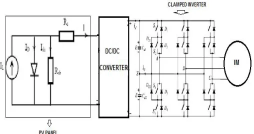
Inverter for a Induction motor(IM) connected PV system[2]. The analysis is carried out on two types of modulation strategies used at three levels MLI, viz. Newly developed third harmonic injection method and Space vector modulation.
Figure 1 Equialent model of considered system .
II. DESIGN OF PV SYSTEM
The corresponding circuit of a PV panel by means of a load. The current production of the PV panel is built up by the given equations:
= − ∗[exp + −1] (1)
= + ( − ) ∗ (2)
= exp( ( − )) (3)
III DC-LINK CAPACITORS VOLTAGE BALANCING
In the earlier papers different methods for DC link capacitor voltages balancing were explained. Many of them have demerits such as need of extra sensor or more switching frequency. Algorithm obtained using only variables and sensors proposed in the current work. For stable DC link voltages balancing, energy flow direction and difference among capacitor voltages is sufficient. By these two attributes and consideration of proper surplus vector, charging or discharging of DC link capacitors can be survived exactly by which method will be explained.
IV.VOLTAGE BALANCING USING SVM
Table1: Internal vector selection for balancing DC link capacitors
Sector
(P>0)
Motoring mode
(P<0)
Regenerative mode
C1<C2 C1>C2 C1<C2 C1>C2
I 211 221 100 110 100 110 211 221
II 221 121 110 010 110 010 221 121
III 121 122 010 011 010 011 121 122
IV 122 112 011 001 011 001 122 112
V 112 212 001 101 001 101 112 212
VI 212 211 101 100 101 and 100 212 211
Figure 2 Choice of correct small vector for capacitor voltage balancing
And Figure 3Redundant vectors waveforms for every sampling time. In the Sector 1; Sector 2
Try to employ standard modulation in the non-linear range will produce a smaller output voltage than an indication. In favor of vector prohibited Adjustable speed drives (ASD) it is real to gain reference voltage amplitude in the motor, because it’s liable to flux and torque, generally forbidden quantities. Control algorithm cannot work accurately if the output voltage is not tied to the input (reference) value. Use of nonlinear modulation and alteration of control, review signals will be stronger indistinct, results to complete utilization of converter properties. Production of upper voltage can be obtained by nonlinear algorithm of modulation known as over modulation (OVPWM). This method cannot figure sinusoidal waveform excluding amplitude of primary harmonic of the output signal is identical to the reference value. It can be managed by appropriate adjustment of voltage space vector length and slant. As in OVPWM region reference vector route lies in part outside of the operational hexagon, there is necessity to regulate its length in positions in which the path is inside the hexagon.
The OVPWM algorithm is alienated into two sub-regions [3]. Initial region is for 1.814<M<1.904, which is probable to influence the length of the vector in a few cases of the trajectory.
ISSN (Print) : 2320 – 3765 ISSN (Online): 2278 – 8875
I
nternational
J
ournal of
A
dvanced
R
esearch in
E
lectrical,
E
lectronics and
I
nstrumentation
E
ngineering
(An ISO 3297: 2007 Certified Organization)
Website: www.ijareeie.com
Vol. 6, Issue 3, March 2017
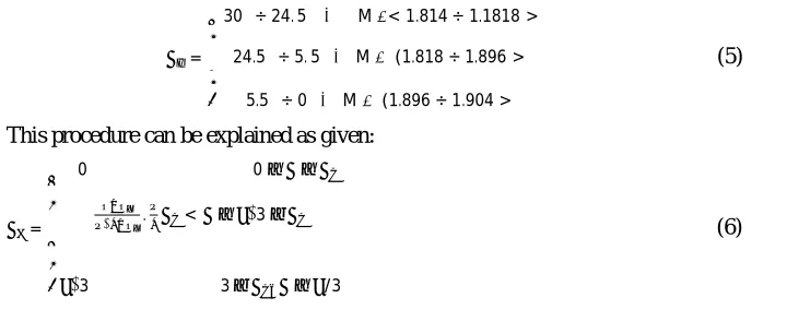
In this calculation outline of low modulation indexes is all the time equal 2. While commanding angle α is lesser than the aP usual modulation process is applied. As αP = f (M) function is mostly non-linear, it has been split into three sections and liberalize (Figure 4). Liberalized attributes of cross angle αP depends on [3] subsequent relation:
=
⎩ ⎪ ⎨ ⎪
⎧30 ÷ 24. 5 ⇔ M∈< 1.814 ÷ 1.1818 >
24.5 ÷ 5. 5 ⇔M∈ (1.818 ÷ 1.896 >
5.5 ÷ 0 ⇔M∈ (1.896 ÷ 1.904 >
(5)
This procedure can be explained as given:
= ⎩ ⎪ ⎪ ⎨ ⎪ ⎪
⎧ 0 0≤ ≤
⁄ . < ≤ ⁄3−
3 3− ≤ /3
⁄
(6)
Subsequent to calculation of customized angle α1 minute modulation indexes are evaluated equally in the first OVPWM region:
m = 2.√ .
√ . (7)
m2 = 2 −m1
= ⎩ ⎪ ⎪ ⎨ ⎪ ⎪
⎧ 0 ÷ 17. 2 ⇔ M ∈ (1.904 ÷ 1.958 >
17.2 ÷ 19.5 ⇔ M ∈ (1.958 ÷ 1.994 >
19.5 ÷ 30 ⇔ M∈ (1.994 ÷ 2.0 >
(8)
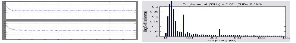
In excess of modulation algorithm is necessary for full consumption of DC-link voltage in ASD. Broadly, it is used to amplify voltage and flux in the high velocity range of stimulation machines. This modulation kind distorts the DC link balancing of capacitors and also increases the level of harmonics in the organization. The below shown results in figure (3), Figure (4) and figure (5) will make the data about the PV voltage generated, three level line voltages and Voltage balancing across the capacitor. The level of harmonics is also included in the figure (6) for the three level inverter connected to the PV.
Website: www.ijareeie.com
Vol. 6, Issue 3, March 2017
Figure 5 DC-Link Balancing of capacitors Figure 6 Total Harmonic Distortion
V. VOLTAGE BALANCING USING NEWLY DEVELOPED THIRD HARMONIC INJECTION
Let the supply voltage of phase a be a reference vector, VA(wt) =Vm sin (wt) as shown in Figure (7) at α=20o. Figure (8) gives the injection current along with the VA (ωt). Figure (9) gives the electric potential of phase a and the
reproduction of current. The waveforms of voltages at the DC-link, Vdn,
Vfn and Von, are given in Figure (11).
These are the potentials which are used to distribute the third harmonic current in the projected path. Hence, by the complex Fourier analysis, the recounting of the voltage, Von, 3k, and angle a can be acquired by the following equations:
, = ( ) 1 + (9 −1) (9)
And the angle of Von, 3k for odd values of k is,
, = tan
( )
( ) ( ) (10)
Von,3k = 0 for even values of k
Figure 8 Voltage of phase a and injection current
Figure 7 Voltage and current of phas-a
ISSN (Print) : 2320 – 3765 ISSN (Online): 2278 – 8875
I
nternational
J
ournal of
A
dvanced
R
esearch in
E
lectrical,
E
lectronics and
I
nstrumentation
E
ngineering
(An ISO 3297: 2007 Certified Organization)
Website: www.ijareeie.com
Vol. 6, Issue 3, March 2017
, = tan
( ) ( )
( ) ( ) (13)
Hence, the phase angle of the main current of the phase a current is -a and -3a corresponding the utility that increases (triple) the utility frequencies, correspondingly. Such that the optimal angle, foot, between VA and If3 is shown in (14).
(fopt )=180-3a (14)
Moreover, the optimum angle among Von, 3 and If3 is ψopt, can be acquired from the following equation:
yopt =qon,3 +3a-180 (15)
From (14) and (15) the phase angle between each of the vectors for different firing angles given by 20o, 40o example of the rectifier mode with α=130o, 150o example of the inverter mode are presented in Figure 11[6]. The amplitude of the optimum injection current for minimum THD, is a function of the DC-link current, Io. Hence, the amplitude of the proposed current can be assumed to be qIo where q is a proportional constant. Then the equation of the proposed current (if3) can be determined from the following equation:
i f 3 = - Io sin(3(wt -a)) (16)
In the case of the phase a voltage, va is the reference voltage. Then the current of phase a can be determined from the following equation:
( ) =
⎩ ⎪ ⎪ ⎨ ⎪ ⎪ ⎧
+ = − sin 3( − ) < − <
− − sin 3( − ) < − <
− = sin 3( − ) ℎ
(17)
The rms value due to the primary devices of the supply current, , can be obtained as shown below
, = + 24 (18)
The value of rms of the fundamental devices with the supply current , can be determined by the Fourier
transform to equation (19). The following equation shows the result.
, =
√ ( )
(19)
Supply current of THD can be obtained from the below
THD= , ,
, (20)
Replacing (20) to (18)and (19) we get
THD= ( ) −1 (21)
The derivative of the THD should be equal to zero for the min THD
=0 (22)
Replacing (22) with (21) the required value of q is given by
The value of is exactly the same as the value obtainedfor the diode rectifier [4], [5]. The theoretical lowest THD related by this method can be determined by replacing (21) from (23). Such that the lowest THD that canbe determined by the third harmonic introduction method is5.12%. The required value of the reproduction current can be determined by (14) and (23) and is given in (24).
=− sin(3 −3 ) (24)
Let q be 1.5 and the variable reproduction current angle, (9) can be modified as shown below
( ) =
⎩ ⎪ ⎪ ⎨ ⎪ ⎪ ⎧
+ = + sin 3( +∅) < − <
− − sin 3( − ∅) < − <
− =− sin 3( − ∅) ℎ
(25)
The value of rms supply current, Ia,rms , can be determined from (25) and rms of the primary devices of the line current, Ia,rms, can be determined by the Fourier transform of the current as given in (17). Replacing with the new values of Ia,rms and Ia,rms into (21) which equals the derivative of the THD by zero, the optimum relation between α
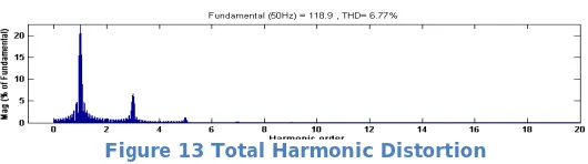
and fopt can be determined, that is the relative to that of previously obtained as (14).Similarly the remaining reference voltages are also developed for phase-b as ( ) and for phase-c as ( ) With respective phase differences. There by the required voltages generated for three level inverter and DC link balancing is given by applying the solved logic. The below shown figure (12) gives the information of three level phase voltages using New THI method and shows a DC link balance of no distortions in Figure (13) when compared to DC link balance using SVM. And also new third harmonic injection method considerably having less THD again when compared to SVM which is shown in Figure (14)
Figure 11 Three phase voltages Figure 12 DC link Balancing
ISSN (Print) : 2320 – 3765 ISSN (Online): 2278 – 8875
I
nternational
J
ournal of
A
dvanced
R
esearch in
E
lectrical,
E
lectronics and
I
nstrumentation
E
ngineering
(An ISO 3297: 2007 Certified Organization)
Website: www.ijareeie.com
Vol. 6, Issue 3, March 2017
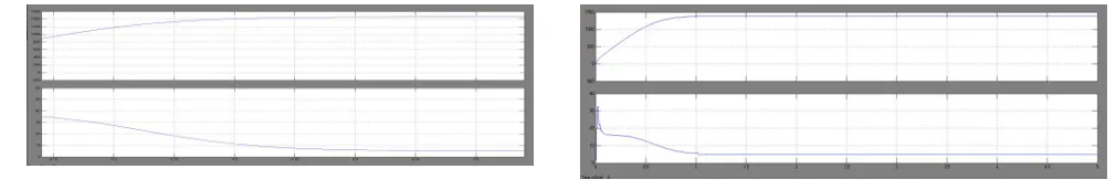
VI. PERFORMANCE OF INDUCTION MOTOR
The below shown figures presents the information about the behaviour of an induction motor in terms of speed and torque for the corresponding modulation techniques.
Figure 15 SVM Figure 16 New Total harmonic Injection method
Figure (15) shows the speed and Torque characteristics obtained by using Space Vector Modulation Technique and Figure (16) shows the speed and Torque characteristics obtained by using New Harmonic reduction technique.
VII. CONCLUSION
Simulation results presented in this paper confirmed efficient operation of three level diode clamped inverter using newly developed third harmonic injection technique injection when compared to designed Space Vector Modulation technique .This method(THI) utilized well efficiently in balancing the DC-Link voltages across the capacitors with less distortions and also with reduced harmonics on the ac side and also offered a simple control when compared to the space vector modulation discussed.This method also worked effectively when it was connected to the Induction motor in maintaining the speed and Torque values..
REFERENCES
[1] B.Vikram Anand, “Design of unipolar phase disposition technique connected to five-level PV Inverter employing Fuzzy control” in International Journal of Industrial Electronics and Electrical Engineering, Volume 4, Issue 2, February- 2016, Page No. 116 -119, ISSN No. 2347 – 6982
[2] B.Vikram Anand“Use of balanced and unbalanced loads by using an isolated W-H Hybrid model with power converters” in International Journal Of Engineering Sciences & Research Technology, Volume 4, Issue 11, November- 2015, Page No.362 -368, ISSN No. 2277 – 9655 [3] C. Lascu, A.M. Trzynadlowski, "Combining the principles of sliding mode, direct torque control, and space-vector modulation in a
high-performance sensorless AC drive", IEEE Transactions on Industry Applications, Vol. 40, Issue: 1, Jan.-Feb. 2004, pp.170-177. [4] C. Lascu, I. Boldea, F. Blaabjerg, "Variable-Structure Direct Torque Control-A Class of Fast and Robust Controllers for Induction
Machine Drives", IEEE Transactions on Industrial Electronics, Vol. 51, Issue: 4, Aug. 2004, pp.785-792.
[5] Joong-Hui Lee, Chang-Gyun Kim, Myung-Joong Youn, "A dead-beat type digital controller for the direct torque control of an induction motor", IEEE Transactions on Power Electronics, Vol. 17, Issue: 5, Sept. 2002, pp.739-746.
[6] S.C. Bera, R. Sarkar, N. Mandal, “An opto-isolator based linearization technique of a typical thyristor driven pump Original Research Article,” ISA Transactions, Vol. 51, No. 1, pp. 220-228, Jan. 2012.
[7] S.C. Bera, N. Mandal, R. Sarkar “A novel technique of using a thyristor driven pump as the final control element and flow indicator of a flow control loop Original Research Article,” ISA Transactions, Vol. 50, No. 3, pp. 496-503, Jul. 2011.