Copyright to IJIRSET www.ijirset.com 12759
SMES based DVR for Mitigating the Voltage
Fluctuations in a Direct Current Vector
Control PMSG Wind Turbine
Acsah Ann Varghese1,S.Bharath 2,Aswathy P.R3
P.G. Student, Department of Electrical and Electronics Engineering, SNS College of Technology, Coimbatore, India1 Associate Professor, Department of Electrical and Electronics Engineering, SNS College of Technology, Coimbatore, India2
P.G. Student, Department of Electrical and Electronics Engineering, SNS College of Technology, Coimbatore, India3
ABSTRACT: The wind turbine technology has developed rapidly as one of the most mature Renewable Power Generation Technologies. With the advances of power electronic technology, Permanent Magnet Synchronous Generators (PMSGs) have increasingly drawn the interest of wind turbine manufacturers. The increased asset utilization,facilitates the penetration of renewable sources and improves the flexibility, reliability and efficiency of the grid, Superconducting Magnetic Energy Storage (SMES) technology has been progressed SMES technology has the potential to bring real power storage characteristic to protect consumer’s loads from the grid voltage fluctuations during various fault conditions. This project analyses the performance of the PMSG wind turbine under fault conditions by mitigating the voltage fluctuations by making use of SMES based DVR and its design is based on simple PI control method to compensate voltage sags. The performance of the Superconducting Magnetic Energy Storage is validated through simulations using MATLAB SIMULINK and the results reveals that the SMES can be a useful alternative DC source for the DVR.
KEYWORDS: SMES, Dynamic Voltage Restorer (DVR), Power conditioning system (PCS), Pulse Width Modulated
I. INTRODUCTION
Conservation of the non-renewable resources motivate to explore the new avenues of resources for electricity generation which could be clean, safe and most valuable to serve the society for a long period. The option came with huge number of hands up a source which is a part of our natural environment and eco friendly is the Renewable Energy Sources (RES).Today’s most rapidly growing renewable energy source is the wind power.
A wind turbine operates either at a fixed speed or variable speed [1].Based on the variable speed operation with pitch control using either a PMSG or DFIG [2], most of the major wind turbine manufacturers are developing new megawatt scale wind turbines .PMSG is a type of synchronous generator in which the excitation field is a permanent magnet instead of a coil. The advantages of the PMSG are: 1) gearless construction [3]; 2) higher efficiency and energy yield; 3) elimination of a dc excitation system [4]; 4) improvement in the thermal characteristics of the PMSG due to the absence of field losses; 5) full controllability of the system for maximum wind power extraction and grid interface; 6) ease in accomplishing fault-ride through and grid support [5]. Therefore when compared to DFIG wind turbine [6],the efficiency and reliability of a VSC- based PMSG wind turbine is assessed to be higher.
Copyright to IJIRSET www.ijirset.com 12760
viable choice to bring solutions to some of the problems experienced in power systems. The power industry demand for more flexible, reliable and fast real power compensation devices provides the ideal opportunity for SMES applications [8].
SMES used for various applications such as Power Quality, Custom Power Stabilization, Voltage/VAR Control, Load Levelling, Dynamic Response, Spinning Reserve, Frequency Control Application [9]. However, here we dealt with SMES Power Quality Application based on DVR for sag compensation. For voltage sag compensation, the dynamic voltage restorer (DVR) which acts as series-connected topology is a more cost-effective solution [10]. In this paper, a superconducting magnetic energy storage unit is introduced as the energy storage unit of the DVR.
II. PMSG WIND POWER GENERATION
A VSC-based PMSG wind turbine is shown in Fig.1. It mainly consists of three parts: Wind turbine drive train, a PMSG and two back to back voltage source converters [11].In the turbine drive train, the rotor blades of the wind turbine catch wind energy and it is then transferred to the generator. A standard PMSG is used for converting mechanical energy into electrical energy with its stator winding directly connected to the grid through a frequency converter. The frequency converter is built by two current regulated voltage-source pulse width modulated (PWM) converters: an MSC and a GSC, with a dc voltage link in between them [11], [12], [13].
Fig.1 Configuration of SMES based DVR in PMSG based wind turbine
Copyright to IJIRSET www.ijirset.com 12761
A. Controller circuit of Machine side converter (MSC)
The direct-current vector control strategy of the MSC, is a nested loop structure as shown in Fig. 2. It consists of three parts :
1) Transformation from speed control to current control. 2) Development of a direct current control mechanism
3) Conversion from current control signals to voltage control signals
Fig.2 controller circuit of MSC
First, the transformation from speed to torque control is accomplished through a speed loop controller. Then the torque control is converted to stator d and q axis current control, while the stator d-axis current is set to zero.
Second, the reference signals to an inner current loop controller are the d and q-axis currents generated by the speed loop controller. It is necessary to point out that a fast current loop controller is crucial to assure high performance operation of the synchronous generator in terms of reduced harmonics and stator current unbalance. However, unlike the conventional vector control strategy that outputs a d- or q-axis. voltage based on a d- or q-axis current error signal. The direct-current vector control mechanism of the MSC outputs d- and q-axis tuning currents ′ and ′ , in which
the input error signal tells the controller how much the tuning current should be adjusted through an adaptive tuning
strategy [15], [16].
Third, due to a VSC structure of the MSC, the stator d and q-axis tuning current signals i’sdand i’sqgenerated by the
current-loop controllers are transferred to stator d- and q-axis voltage signals v*sdand v*sqto control the synchronous
generator. The conversion from the current to voltage control signals is implemented through (1), which is equivalent to the transient dq (1) after being processed by a low-pass filter to reduce the oscillation of d- and q-axis reference voltages applied directly to the converter.
V*sd = −Rs i’sd −ωeLq isq
V*sq =−Rsi’sq+ωeLdi’sd+ωeψf (1)
B. Controller Circuit of Grid Side Converter
The direct-current vector control strategy of the GSC is shown in Fig. 3 is implemented through a nested-loop controller in the following way:
1) Transforming the dc-link voltage and reactive power control to d- and q-axis current control. 2) Developing a direct current control scheme.
Copyright to IJIRSET www.ijirset.com 12762 Fig.3 controller circuit of GSC
First, the dc-link voltage control is transformed to d-axis current control through a dc-link voltage controller, and the ac system reactive power control is transformed to q-axis current control through a reactive power controller.
Second, an inner current-loop controller is developed based on a direct-current vector control mechanism by generating
d- and q-axis tuning current signals i’sdand i’sq through an adaptive tuning strategy [15], [16]. The purpose of the
current loop controller is to assure the highest power quality of the ac system in terms of harmonics and unbalance. Therefore, similar elimination of the current loop is not an option for GSC control.
Third, the d and q-tuning current signals i’sdand i’sqgenerated by the current-loop controllers are transferred to d- and q-voltage signals v*d1 and v*q1 due to the VSC structure for the GSC. The conversion from the current to voltage
control signals is implemented through V*d1 = Rf i’d −ωsLf i’q + vd
V*q1 =Rfi’q+ωsLfi’d (2)
III. CONFIGURATION OF SMES
Copyright to IJIRSET www.ijirset.com 12763 Fig.4 Component of SMES
For a SMES system, the inductively stored energy (E in Joule) and the rated power (P in Watt) are commonly the given specifications for SMES devices, and can be expressed as follows:
E= LI2 (3) P = =L =VI (4)
Where L is the inductance of the coil, I is the dc current flowing through the coil, and V is the voltage across the coil. Although SMES systems may not be cost effective, at the present time, they have a positive cost and environmental impact by reducing fuel consumption and emissions..
IV. INTEGRATION OF SMES WITH DVR
The basic structure of a DVR based on SMES is shown in Fig. 5. It consists of super conducting magnetic energy storage unit, capacitor bank, voltage source inverter (VSI), low pass filter and a voltage injection transformer.
Copyright to IJIRSET www.ijirset.com 12764
Where SMES is designed based on its simple principle. Its energy released circuit model is as shown in Fig. 6.
Fig.6 SMES energy released circuit
The circuit model has three operating states:
1) Energy-charging state (close K1 and K3, open K2); 2) Energy-storing state (close K2 and K3, open K1); 3) Energy discharging state (close K2, open K1 and K3).
During charging cycle, solenoid coil is place across DC source. When certain amount of energy stored in the coil then DC source removed & solenoid coil is shorted through superconductor material. So current continuously flow through coil without decay & energy is stored in solenoid coil. For discharging of solenoid coil energy, negative voltage applied across the coil.In order to mitigate the simulated voltage sag in practical application, a discrete PWM-Based control scheme is implemented, with reference to DVR as shown in Fig. 7. The aim of the control scheme is to maintain a constant voltage magnitude at the sensitive load point, under the system disturbance. The control system only measures the rms voltage at load point; The DVR control system exerts a voltage angle control as follows:
Voltage sag is created at load terminals by a three phase fault as shown in Fig. 4. Load voltage is converted into per unit quantity and is passed through a sequence analyzer. The magnitude is then compared with reference voltage (Vref) through which error signal is fed to PI controller. This voltage is then fed to triggering circuit. Pulse width modulated (PWM) control technique is applied for inverter switching so as to produce a three phase 50 Hz sinusoidal voltage at the load terminals. Chopping frequency is in the range of a few KHz. The IGBT inverter is controlled with PI controller in order to maintain 1 p.u. voltage at the load terminals i.e. considered as base voltage =1p.u.
Fig.7 SMES based DVR
The PI controller processes the error signal and generates the required angle δ to drive the error to zero, for example;
the load rms voltage is brought back to the reference voltage. It should be noted that, an assumption of balanced network and operating conditions are made. The modulating angle δ or delta is applied to the PWM generators in phase
Copyright to IJIRSET www.ijirset.com 12765
VA= Sin (ωt +δ) (5) VB= Sin (ωt+δ-2π/3) (6) VC =Sin (ωt +δ+2π/3) (7) An advantage of a proportional plus integral controller is that integral term causes the steady-state error to be zero for a step input. PI controller input is an actuating signal which is the difference between the Vref and Vin. Output of the
controller block is of the form of an angle δ, which introduces additional phase-lag/lead in the three phase voltages. The
output of error detector is
Vref-Vin. (8)
Vref equal to 1 p.u. voltage
Vin voltage in p.u. at the load terminals.
The controller output when compared at PWM signal generator results in the desired firing sequence.
V. SIMULATION AND RESULTS
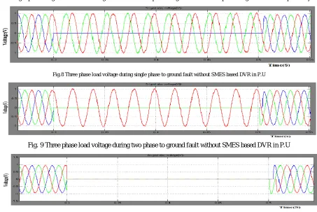
The first simulation was carried out without SMES based DVR and a single phase to ground fault is applied to the system at point with fault resistance of 0.44Ω for time duration of .3 to .5s which result voltage dip as shown in Fig. 8 for single phase to ground fault and Fig 9 and 10 for two phase to ground and three phase to ground fault respectively.
Fig.8 Three phase load voltage during single phase to ground fault without SMES based DVR in P.U
Fig. 9 Three phase load voltage during two phase to ground fault without SMES based DVR in P.U
Fig. 10 Three phase load voltage during three phase to ground fault without SMES based DVR in P.U The second simulation is the test system for SMES based DVR. It is composed by a 110 kV, 50 Hz generation system,
which feed a distribution network through a transformer connected in Y/Δ, 115/11 kV. We verify the working of DVR
Copyright to IJIRSET www.ijirset.com 12766
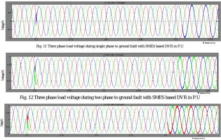
presence of Superconducting magnetic energy storage unit (SMES) is analyzed for symmetrical three phase to ground fault, two phase to ground fault & single phase to ground fault. The simulation results of the test system using SMES based DVR during various faults is shown in fig 11, fig 12 and fig 13
Fig. 11 Three phase load voltage during single phase to ground fault with SMES based DVR in P.U
Fig. 12 Three phase load voltage during two phase to ground fault with SMES based DVR in P.U
Fig. 13 Three phase load voltage during three phase to ground fault with SMES based DVR in P.U
VI.CONCLUSION
A new design which incorporates a superconducting magnetic energy storage module as a DC voltage source to mitigation voltage sags in a PMSG based wind turbine under fault conditions and enhances power quality of a distribution system based on DVR has been presented. The Simulation results prove that the SMES can be a useful alternative DC source for the DVR.
REFERENCES
[1] R. Zavadil, N. Miller, A. Ellis, and E. Muljadi, “Making Connections: Wind Generation Challenges and Progress,” IEEE Power Energy Mag.,vol. 3, no. 6, pp. 26–37, Nov. 2005.
[2] Z. Chen, J. M. Guerrero, and F. Blaabjerg, “A Review of the State of the Art of Power Electronics for Wind Turbines,” IEEE Trans. Power Electron.,vol. 24, no. 8, pp. 1859–1875, Aug. 2009.
[3] Y. Chen, P. Pillary, and A. Khan, “PM Wind Generator Topologies,” IEEE Trans. Ind. Appl., vol. 41, no. 6, pp. 1619–1626, Nov./Dec. 2005.
[4] H. Polinder, S.W. H. de Haan,M. R. Dubois, and J.Slootweg, “Basic Operation Principles and Electrical Conversion Systems of Wind Turbines,” presented at the Nordic Workshop Power Ind. Electron., Trondheim, Norway, Jun. 14–16, 2004.
[5] G. Michalke, A. D. Hansen, and T. Hartkopf, “Control Strategy of a Variable Speed Wind Turbine with Multipole Permanent Magnet Synchronous Generator,” presented at the 2007 Eur.Wind Energy Conf. Exhib., Milan, Italy, May 7–10, 2007.
[6] A Grauers, “Efficiency of Three Wind Energy Generator Systems,” IEEE Trans. Energy Convers., vol. 11, no. 3, pp. 650–657, Sep. 1996. [7] Sergio faias, Patricia Santos, Jorge Sousal, Rui Castro,” An Overview on Short Term and Long Term Response Energy Storage Devices for
Power Systems Applications”.
Copyright to IJIRSET www.ijirset.com 12767 [9] Piyasak Poonpun, Student Member, IEEE, and Ward T Jewell,Fellow, IEEE,”Analyses of the Cost Per Kilowatt Hour to Store Electricity”,
IEEE Trans.on Energy Conversion,Vol.23,No.2,June 2008.
[10] M.H.Haque “Compensation of Distribution System Voltge sag by DVR and DSTATCOM” Power Tech Proceedings, 2001 IEEE Porto, Volume: 1,10-13 Sept.2001 pages: 5 pp. Vol.1
[11] J. Belhadj and X. Roboam, “Investigation of Different Methods to Control a Small Variable-Speed Wind Turbine With PMSM Drives,” J. Energy Resources Technol., vol. 129, pp. 200–213, Sep. 2007.
[12] M. Chinchilla, S. Arnaltes, and J. C. Burgos, “Control of Permanent Magnet Generators Applied to Variable-Speed Wind-Energy Systems Connected to the Grid,” IEEE Trans. Energy Convers., vol. 21, no. 1, pp.130-135,Mar 2006.
[13] J. Matas, M. Castilla, J. M. Guerrero, L. Garcia de Vicuna, and J. Miret, “Feedback Linearization of Direct-Drive Synchronous Wind-Turbines Via a Sliding Mode Approach,” IEEE Trans. Power Electron., vol. 23, no. 3, pp. 1093–1103, May 2008
[14] A. D. Hansen, P. Sørensen, F. Iov, and F. Blaabjerg, “Control of Variable Speed Wind Turbines With Doubly-Fed Induction Generators,” Wind Eng.,vol. 28, no. 4, pp. 411–432, Jun. 2004.
[15] M. S. Iyer and D. C. Wunsch II, “Dynamic Reoptimization of a Fedbatch Fermentor Using Adaptive Critic Designs,” IEEE Trans. Neural Netw.,vol. 12, no. 6, pp. 1433–1444, Nov. 2001.
[16] W. Liu, G. K. Venayagamoorthy, and D. C. Wunsch II, “A Heuristic Dynamic-Programming-Based Power System Stabilizer for a Turbo Generator in a Single-Machine Power System,” IEEE Trans. Ind. Appl., vol. 41, no. 5,pp. 1377–1385, Sep. 2005