IJEDR1401079
International Journal of Engineering Development and Research (www.ijedr.org)448
Development and Structural Analysis of Masthead for
a Twin Boom Stacker
1
K Vamsi Krishna,
2S Porchilamban
1Post Graduate Student, 2Assistant professor1Mechanical and production engineering, Sathyabama university, Chennai,India
1[email protected], 2[email protected]
_____________________________________________________________________________________________________ Abstract—Bulk material handling plays a vital role in the effective operation of process industries. In Visakhapatnam steel plant is one such shore based process industry operating at 120% of rated capacity of 3.0 MT/annum. Liquid steel is in the process of expanding its capacity to 6.3 million ton per annum, around 24MT/annum of bulk materials are to be handled in Visakhapatnam steel plant(VSP). VSP is equipped with peripheral unloading yard for the first time in India to unload the bulk materials in plant premises by transporting by locos, to plant wagon pushers of railways. Raw material plant in VSP is having unloading facilities like rotary wagon tripper, storage yard with machines for stacking and reclaiming and distribution belt conveyor system to feed various raw materials to different process plants by proportioning and by sizing. Thus stackers play a critical role in meeting the demand of bulk material. This project deals with the strengthen of MAST HEAD of twin boom stacker by redesigning to avoid frequent failures.The twin boom stacker is used to stack the raw material in two parallel yards depending on the requirement. The reliability of the twin boom stacker is utmost important for stacking the materials in the storage yard for better logistics. The ageing of twin boom stacker with the prolonged operation resulted in uneven loads or jerks on MAST HEAD. This has resulted in frequent failures of MAST HEAD. The design modification has been verified by modeling the MAST HEAD using SOLIDWORKS Version 2012 and analyzed using FEM package ANSYS 14.5. The Necessary stress strengthening has been made based on the preliminary analysis by increasing the thickness of the spacer and observed that the stresses are within the tolerable limits and are discussed in the topic RESULTS.
Thus the design has been frozen and the fabricated drawing has been released for implementation.
IndexTerms—mast head re-designing , FEA analysis.
I. INTRODUCTION
When there is a need of transport of material in an organized and effective manner, we need assistance of a special branch of engineering known as MATERIAL HANDLING or BULK MATERIAL HANDLING SYSTEMS. This type of material handling system came to existence in the year 1965 for the transportation of iron and cement in the mid -west of South Africa. The easiest way to describe is that it moves the products from one location to another location. The other thing should be noted that material handling also deals with the storage, waste handling and assembly line management.
A stacker is a large machine used in bulk material handling applications. A stacker’s function is to stack bulk material such as ores, base mix and cereals onto a stockpile. Stackers are nominally rated tph (tones per hour) for capacity and normally travel on a rail between stockpiles in the stockyard. A stacker can usually move in at least two directions at least two directions typically: horizontally along the rail and vertical by luffing its boom. Luffing of the boom minimizes dust by reducing the height that the coal needs to fall to the top of the stockpile. The boom is luffed upwards as the stockpile height grows.
Some stackers are able to rotate by slewing the boom. This allows a single stacker to form two stockpiles, one on either side of the conveyor. Stackers are used to stack in different patterns, such as cone stacking and chevron stacking
A. Raw Material Handling Plant
RMHP is raw material handling plant in vizag steel plant. Its duty is to manage the raw material that they receive from the mines. First they crush the material into small pieces. Secondly they segregate the material as per to required ratio
Then the material is transported back to the dept which it is concerned based on the sizes. For the above duties to perform they use certain equipments to handle raw material like
1. Crusher. 2. Stacker. 3. Reclaimer. 4. Belt conveyors.
Stacker is equipment used to stack the material from a pile (raw material) and transfer it to the department. There are different types of stacker as per to the application of the raw they are:
1. Single boom stacker 2. Twin boom stacker. 3. Radial stacker 4. Slewing stackers 5. non-slewing stackers
Boom luffing
IJEDR1401079
International Journal of Engineering Development and Research (www.ijedr.org)449
Mechanical devices mounted on MAST HEADII. PROBLEM DEFINITION
The raw material handling department, which manages the storage and supply of raw materials for the plant is one of the prime departments. The detailed view of the RMHP is given in the layout. It consists of 12 beds each of dimensions 33m x350m .In this it has 3 beds allotted for iron ore fines 1 bed for lumped iron ore and 2 beds for sized iron ore.
In general case the stocking capacity of the plant is 14 M T per annum and they wish to increase it to 18 M T per annum. The plant has 4 TWIN BOOM STACKERS out of which 3 will be in operation and 1 will be under maintenance.
The TWIN BOOM STACKER now is working under excess loading condition. Thus the idea is to maintain the strength of the MAST HEAD by performing necessary analysis so that the working condition of the stacker will be in safe condition
III. WORK METHODLOGY
A. Geometry creation and meshing
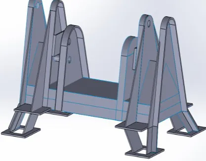
Geometry of the MAST HEAD is needed to carry out this analysis. Solid model of the MAST HEAD was created in solid modeling environment called “SOLIDWORKS Ver. 2012”.Solid model is the base for carrying out any FEA analysis. Solid model of the MAST HEAD that was created in SOLIDWORKS Version 2012 solid modeling environment is shown in the figure. The created solid model of the unit cell was imported in to the ANSYS. Solid model used in any FEA analysis can be very simple and at the same time it reflects the physical reality of the MAST HEAD. Solid model will have to be turned into to FEM model by dividing the solid model into number of small elements. This process is called discritization. Discritization is the process of dividing the solid model into finite number of elements. And the CAD Model of MAST HEAD is shown in fig 3.1
IJEDR1401079
International Journal of Engineering Development and Research (www.ijedr.org)449
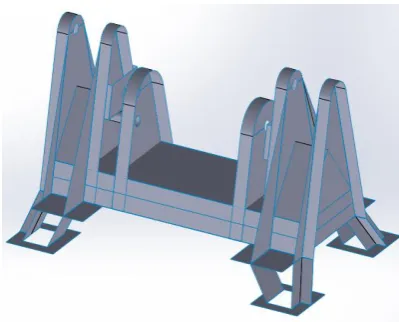
Fig 3.2 Mid surfaces Model of MAST head
B. Typical FEM procedure to carry out this analysis
1. Dividing the solid model into number of elements and then connecting these elements with each other meshing and thereby obtaining the finite element model.
2. Applying boundary conditions. 3. Solving the problem.
Element Type: shell 63 Material Properties
Table3: Material properties
Material used mild steel
Poisons ratio 0.3
Young’s modulus 210e3
Degrees of freedom 6 (UX, UY, UZ, ROTX, ROTY, ROTZ)
C. Loading the MAST HEAD
The application of boundary conditions plays a vital role in the finite element analysis. The bottom portion of the MAST HEAD is fully constrained as it is bolted to the lower portion. The rope on the pulleys is subjected to tension.
Static Analysis
Static analysis calculates the effect of steady load conditions on a structure while ignoring inertia and damping effects, such as those caused by time varying loads. A static analysis therefore can include steady inertia loads (such as gravitational and rotational velocity). Static analysis is used to determine the displacements, stresses, strains and forces in the structures or components caused by loads that do not induce significant inertia and damping effects. The kind of loading that can be included in static analysis are
Externally applied forces and pressure
Steady state inertia forces (such as gravity and rotational velocity)
Fig 3.4: Applying the boundary conditions to the MAST HEAD.
IV. RESULTS AND DISCUSSIONS
The results from the Static Analysis are obtained as contours (i.e. color bands) on the profile of the Twin Boom Stacker. The resultant displacement value is to be less than the acceptable limit.
IJEDR1401079
International Journal of Engineering Development and Research (www.ijedr.org)449
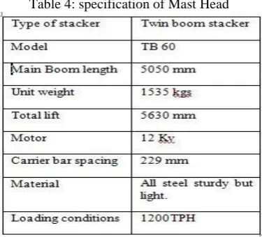
Table 4: specification of Mast HeadVon-mises stress refers to a failure theory called the "Von Mises - Hencky criterion also known as distortion energy theory is used for ductile failure". In an elastic body that is subject to a system of loads in 3 dimensions, a complex 3 dimensional system of stresses is developed. That is, at any point within the body there are stresses acting in different directions, and the direction and magnitude of stresses changes from point to point. The Von Mises criterion is a formula for calculating whether the stress combination at a given point will cause failure. There are three principal stresses acting at a point in X,Y & Z directions on the material, Von-mises found that even though none of the principal stresses exceeds the yield stress of the material, it is possible for yielding to result from the combination of stresses. The Von Mises criteria is a formula for combining these 3 stresses into an equivalent stress, which is then compared to the yield stress of the material. It is used for ductile materials such as metals and is given by :
( ) ( ) ( ) .
Where S1, S2, S3 and Se are the principal stresses acting in the X, Y, Z directions and Se the equivalent stress. Von-mises stress contour of the AHU shell should be less than the titanium material allowable stress value of 240 MPa.
A. Static analysis
After applying the boundary conditions, the problem was solved by the ANSYS Iterative Solver. ANSYS solver formulates the governing structural stress strain equations for each and every element and these formulated governing equations were solved for the deformations from which all the other quantities such stresses, strains etc can be calculated.
Fig 4.1-Deformation at the point of loading (original model)
IJEDR1401079
International Journal of Engineering Development and Research (www.ijedr.org)449
As the stresses are more in the original model, it has been modified by increasing the thickness of spacer by 8mm. The following results are for the modified model.Fig 4.3 Deformation at the point of loading, when the spacer size is increased by 8mm(modified model).
Fig4.4: stress distribution at the point of loading (modified model)
B. Comparison of Analysis results of both models
A review on the analysis of both models has been carried out to ensure the performance of both models. From the observation it is clear that the performances of modified model of the MAST HEAD on the given loading and boundary condition slightly varying from the base model. So the objective is achieved by utilizing the finite element optimization techniques. The comparison of analysis results are tabulated in the table below.
Table5: comparison of results
V. CONCLUSION
The results of the structural analysis of the proposed model are compared shows that the stresses developed are within the allowable stress limit of 240 MPa.To validate the results, similar analysis is done on the original model. It is observed that stresses developed in the in the redesign model are slightly lower than the original model
.
REFERENCES
[1] Twin boom stacker manual from RMHP department, V.S.P [2] Technical drawings from Visakhapatnam steel plant. [3] ANSYS VER14.5 User Manual.
[4] Solidworks Ver 2012 User Manual.
[5] JN Reddy., “An Introduction to the Finite Element Method” Tata McGraw Hill, 3rd Edition, New York. 2005.
[6] Ghosal. S, Misra.D, Saha.T.K, Chakravorthy.D, Failure analysis of stacker-cum-reclaimer in ore handling plant, Journal of failure analysis and prevention, vol 8, pages 564-571, 2008.
[7] K. Krishnapillai, R. Jones, D. Peng, Theoretical and Applied Fracture Mechanics, volume 50, pages30–48, 2008.
[8] Marina Novak, BojanDolsak, Intelligent FEA-based design improvement , journal of Engineering Applications of Artificial Intelligence , volume 21, pages 1239– 1254,2008
IJEDR1401079
International Journal of Engineering Development and Research (www.ijedr.org)449
1. Mr. K.Vamsi Krishna pursuing M.E in Computer Aided Design, Mechanical and production Engineering inSATHYABAMA UNIVERSITY, CHENNAI