© 2014 IJEDR | Volume 3, Issue 1 | ISSN: 2321-9939
IJEDR1501013
International Journal of Engineering Development and Research (www.ijedr.org)59
Design and Implementation of 16 bit Floating Point
Processor for FFT applications
1
Deepak Dave,
2Aarti Bakshi
1M.E Student, 2Assistant Professor 1Electronics and Telecommunication, 1
Shree L. R. Tiwari College of Engineering, Thane, India
________________________________________________________________________________________________________
Abstract - Floating point is considered to be an important format in which data is represented in fraction values. Floating Point calculation can be a daunting task for any processor because of the amount of resources and memory it takes for calculation. In this paper, we have presented and implemented a floating point architecture for application in FFT.
Index Terms - Butterfly; Field Programmable Gate Array (FPGA); Verilog HDL; 1024-point FFT.
________________________________________________________________________________________________________
I.INTRODUCTION
The study of speech signals along with its processing methods is called speech processing. Since the dawn of computers and modern VLSI techniques, digital processing application has increased on an exponential scale. This has lead to an advancement in both storage and extensive processing of speech and audio signals [1]. Some of the aspects of speech processing include the acquisition, manipulation, storage, transfer and output of speech signals. As the processing chip has become smaller the processing it can do has inversely increased. Mathematical techniques of digital processing have now been released to the hardware using different techniques [2].
Since the advent of the VLSI technology FPGA has always had an advantage over the other technologies because of its robust architecture and also since it is programmable.
FPGAs are a collection of programmable logic cells interrelated by a matrix of wires and programmable switches. Every cell executes a simple logic function defined by a user's program. An FPGA has a huge amount (64 to over 20,000) of these cells available to use as building blocks in complex digital circuits [3]. Tradition hardware has never been so simple to build up. The facility to maneuver the logic at the gate level means we can create a custom processor to proficiently put into practice the preferred task. By simultaneously performing all of the algorithm‟s subfunctions, the FPGA can do better than a DSP by as much as 1000:1 [1] [2].
Information on the frequency content of a speech signal can be advantageous in many applications that include speech recognition, speech enhancement, pitch and formant estimation just to mention a few. As the speech is a continuous time signal it is first important to convert it into its frequency domain. For such a purpose Fourier transforms are used. The Fourier Transform breaks a waveform (a function or signal) into an alternating illustration, characterized by sine and cosines. The Fourier Transform illustrates that every waveform can be re-written as the summation of sinusoidal functions. While the Fourier Transform is a stunning mathematical means, its extensive fame is due to its realistic application in almost every field of science and engineering[4].
Fast Fourier Transform (FFT) is an efficient implementation of Discrete Fourier Transform (DFT). The processing of real time digital signal came to realize when FFT was invented, which led to its application in many domains such as communication, the radar, and the reconnaissance applications. No doubt Altera and Xilinx had developed the corresponding Fast Fourier Transform Intellectual Property core, their prices were so high that their usage for common research purpose was not feasible. Hence, many researchers and scientists started to design, FFT processors, according to their own needs and customization for themselves. The hardware realization methods for FFT includes the use of a Digital Signal processor, FFT dedicated chip and FPGA [2].
The FFT operation not only reduces the throughput rate of the entire system, but also consumes more time. Moreover the DSP software cannot provide the optimum resolution when the number of input increases. Again by using the FFT dedicated chip, the speed can be achieved as per the requirement, but again the problem of bad expansibility comes into the picture [1], [3]. With the recent development in FPGA over the subsidiary years, FPGA is most suitable for high speed real time signal processing system due to parallel signal processing architecture.
IJEDR1501013
International Journal of Engineering Development and Research (www.ijedr.org)60
Data involving floating point has been a challenge since the computer was invented. Recent micro-processors have inbuilt Floating point processors to meet its floating point needs. Floating point helps engineers and scientist carry out complex mathematical calculation easily and more accurately. The problem with floating point architecture is that the process takes longer time than simple arithmetic and also the resources used are more. In this paper, we have implemented a 16-bit floating point processor, which will be used in FFT applications.II.BASIC PRINCIPLE OF FOURIER TRANSFORM
A.Fast Fourier Transform
A Fast Fourier Transform is a well-organized algorithm to work out the Discrete Fourier Transform in addition to its inverse[2]. There are several discrete FFT algorithms concerning an ample collection of mathematics, from straightforward complex-number arithmetic to group theory as well as number theory. Fast Fourier Transform is an exceedingly proficient process for computing the DFT of a finite sequence and involves a reduced amount of calculation than that of direct valuation of DFT. It trims down the calculation by taking benefit of the reality that the computation of the coefficients can be processed iteratively [4],[6]. Owing to this, the FFT computation technique is used in the digital spectral examination, filter simulation, autocorrelation and pattern identification [7].
A DFT decomposes a series of values into components of dissimilar frequencies. This act is helpful in various fields, but computing it straightforwardly from the description is frequently too slow to be realistic. An FFT is a technique to work out the similar outcome more rapidly. To work out on a DFT of N points in the apparent way, using the explanation, takes O(N2) mathematical operations, while an FFT can compute the identical outcome in only O (NlogN) operations [2].
The dissimilarity in speed can be significant, mainly for lengthy data sets where N may be in thousands or millions- the calculation time can be abridged by more than a few orders of magnitude. In such cases, the enhancement is approximately proportional to N/log (N) [8]. This enormous improvement made a lot of DFT-based algorithms more practical. FFT‟s are of immense importance to a wide variety of applications, commencing from digital signal processing and solving partial differential equations to algorithms for swift multiplication of outsized integers.
The most renowned FFT algorithms relies upon the factorization of N, but there are FFT with O (N log N) complications for each and every N, even for prime N. Several FFT algorithms simply depend on the reality that is a Nth primitive root of unity, and therefore can be applied to analogous transforms over any restricted field [9]. The FFT makes use of the two fundamental properties of the twiddle factor - the symmetry property and periodicity property which shrinks the number of complex multiplications requisite to carry out DFT. There are essentially two classes of FFT algorithms.
1) Decimation In Time (DIT) algorithm
2) Decimation In Frequency (DIF) algorithm.
In DIT, the sequence for which we need the DFT is divided successively in smaller sequence and the DFTs of these subsequences are united in an assured model to gain the essential DFT of the complete sequence. In DIF, the frequency samples of the DFT are decomposed into smaller and smaller subsequences in a parallel manner[2],[10].
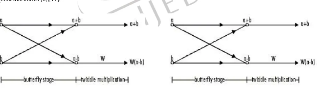
In the DIT algorithm, the twiddle multiplication is performed before the butterfly stage, whereas for the DIF algorithm, the twiddle multiplication comes after the Butterfly stage. The term 'FFT' is in fact somewhat ambiguous, because there are quite a lot of frequently used „FFT‟ algorithms. Both DIT and DIF rely on the recursive decomposition of an N point transform into 2 (N/2) point transforms [2],[11].
B.Floating point representation of data
In view of the fact that computer memory is limited, we cannot accumulate numbers with infinite precision, no matter whether we use binary fractions or else decimal ones: at some point we have to cut off. To an engineer building a highway, it doesn‟t matter whether it‟s 10 meters or 10.0001 meters broad – his dimensions are most likely not accurate in the first place. To someone crafting a microchip, 0.0001 meters is a vast difference. But he‟ll not at all deal with a distance greater than 0.1 meters. A physicist requires to apply the speed of light in addition to Newton‟s gravitational constant simultaneously in the same computation.
© 2014 IJEDR | Volume 3, Issue 1 | ISSN: 2321-9939
IJEDR1501013
International Journal of Engineering Development and Research (www.ijedr.org)61
To assure the former two, a number format has to offer accuracy for numbers at an extremely different range of magnitudes. To suit the latter, it must be feasible to do computation that engages numbers with special magnitudes. Basically, having a fixed number of integer and fractional digits is not useful – and the way out to this problem is by representing in Floating point. Floating point was implemented in 1942 in a commercial computer and in 1985 was standardized by the IEEE.
In computing, floating point is a technique of representing a rough calculation of a real number that can sustain a balance between range and precision. A number is represented more or less to a fixed number of significant digits (the Significand) and balanced by means of an exponent. The base used for scaling is generally 2, 10 or 16. A number can be characterized exactly in the following form:
Significand × base exponent
The phrase floating point refer to the verity that a number‟s radix point (decimal point, or, more commonly in computers, binary point) can "float"; that is to say, it can be positioned anywhere relative to the significant digits of the number. This location is designated as the exponent component, and hence the floating-point representation can be considered as a scientific notation.
Floating-point arithmetic is considered a mysterious subject by a lot of people. This is slightly amazing since floating-point is ever-present in computer systems. More or less each language has a floating-point data type; computers beginning from PCs to supercomputers encompass floating-point accelerators; nearly ever compiler will be called upon to compile floating-point algorithms periodically; and virtually every operating system must counter floating-point exceptions for example overflow or underflow.
A diversified version of floating-point representation is used in computers from quite a long time. Ever since the 1990s, the most generally encountered depiction is that defined by the IEEE 754 Standard.
The IEEE 754 standard has specified a binary16 as having 1-bit for the Sign bit, 5-bits for the Exponent width and 11-bits for the Significand precision out of which 10-bits are unambiguously stored. The format is depicted as follows:
Sign Exponent (5 bit) Significand (10 bit)
C.FPGA: Need And Working
FPGA, namely, field programmable gate arrays, has a higher clock frequency and small internal delay. With all control logical functions implemented by hardware, it is fast and efficient. An FPGA-based data acquisition system has fast timing, flexible composition. It is easy to be modified, and very suitable for high-speed data acquisition applications.
Considering the FPGA‟s advantages in high speed data acquisition, an FPGA-based expanded circuit was designed. The circuit was used to perform A/D channel oversampling, and the subsequent digital filtering for the sampled signals. Then the signals processed by FPGA were sent to the DSP board where a control algorithm was performed to compute output signals. The output signals were sent back to the FPGA board and transferred to analog signals by D/A modules in the expanded board. In this way, the accuracy of the sampled signals was improved, the amount of noise in the signals was reduced, while a relatively low operation rate of the digital controller was kept and the burden of the DSP would not be increased.
III.PROPOSED SYSTEM
A. Design of FFT Architecture
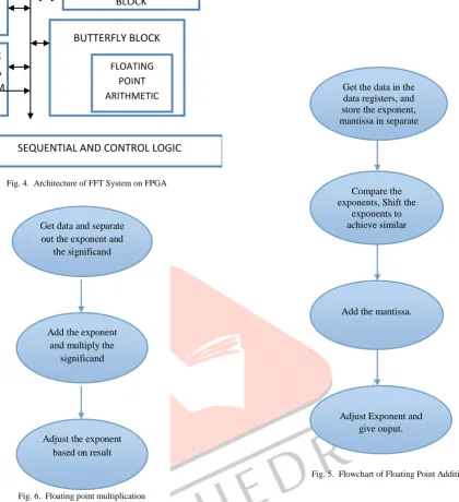
Architecture of the Fast Fourier Transform block is shown in the Fig.4 below. The architecture is divided into several modules which will be made to run in sequence with the sequential logic unit. The sequential logic unit looks after all the operation of the FFT block.
The Sequential and control logic unit is responsible for giving control of the RAM and ROM to the appropriate block, For example, when computing the 1st butterfly stage, RAM 1 is used as a read RAM and RAM 2 is used as a write RAM. The butterfly block is responsible for computing the multiplication and addition of the data. The floating point arithmetic block takes care of all floating point operations. The sequential and control a logic unit informs the address decode block which address of the RAM or ROM should be accessed during an operation. The address decode block passes the address for processing. It also decodes the processing stage and chooses the appropriate ROM or RAM address [2].
B. Floating Point Architecture
The floating point block is responsible for all floating point operations in the FFT architecture. The design of the architecture is given in Fig. 4. The diagram in Fig.5 explains how the FPGA is programmed to solve floating point additions.
First the data is compared to see if the exponents are matching. If not, then the significand is moved left or right depending on the values of the difference in the exponent. When the exponents are found to be similar the significands are added. Now if an overflow or underflow occurs with the addition then the exponent is adjusted accordingly so that the format is same.
The Fig. 6 shows the steps taken by the FPGA in achieving floating point multiplication. In implementing multiplier block the FPGA synthesizer implements a DSP48 multiplier block to achieve multiplication operation using a pipeline structure.
IJEDR1501013
International Journal of Engineering Development and Research (www.ijedr.org)62
Fig. 5. Flowchart of Floating Point Addition
The RTL schematic is shown in Fig.7, Fig.8, Fig.9, Fig.10. As the diagram shown, the data_1 and data_2 are the input to the block for the addition and also multiplication operation. The start pin starts the addition process. The start pin also changes the state of the block from the idle state to the addition state. The Explored RTL schematic block of Fig.8 and 10 shows the amount of resources used by each block. Floating point addition, due to the adjusting of exponent takes more resources and since the DSP48 block is used for multiplication the resources used by multiplication block is shown to be quite less
Fig. 4. Architecture of FFT System on FPGA
FLOATING POINT ARITHMETIC
SEQUENTIAL AND CONTROL LOGIC R
A M 1
R A M 2 ROM
BUTTERFLY BLOCK ADDRESS DECODE
BLOCK
Get the data in the data registers, and store the exponent, mantissa in separate
register
Compare the exponents, Shift the
exponents to achieve similar exponent values
Add the mantissa.
Adjust Exponent and give ouput.
Fig. 6. Floating point multiplication
Get data and separate out the exponent and
the significand
Add the exponent and multiply the
significand
Adjust the exponent based on result
Fig. 7. RTL Schematic of Floating Point Addition
© 2014 IJEDR | Volume 3, Issue 1 | ISSN: 2321-9939
IJEDR1501013
International Journal of Engineering Development and Research (www.ijedr.org)63
IV.RESULTS AND DISCUSSION
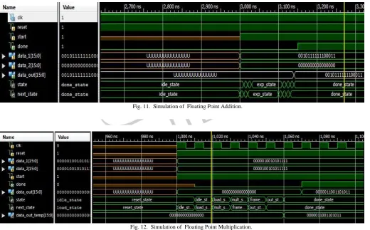
The VHDL code is written and simulated in Xilinx 14.5 ISE. The simulation waveforms are shown in Fig. 11 and Fig. 12. The VHDL is written for speed over resource space as for FFT operation on real time signals, we need to be as fast as possible.
V.CONCLUSION
A Floating point architecture with fast execution times is ideal for Real time application where minimum delay is the need. The architecture designed helps us achieve this goal.
Fig. 9. RTL Schematic of Floating Point Multiplication
Fig. 10. RTL Schematic of Floating Point Multiplication
Fig. 11. Simulation of Floating Point Addition.
IJEDR1501013
International Journal of Engineering Development and Research (www.ijedr.org)64
REFERENCES[1] Chandrakanth V, Srijan Tripathi, “Customized Architecture For Implementing configurable FFT on FPGA,” Third IEEE International Advance Computing Conference, 2012, pp. 1279-1282.