Performance Evaluation of a MIMO-On-Body System
in a Mine Environment
Moulay El Azhari1, Mourad Nedil1, *, Ismail B. Mabrouk2, Larbi Talbi2, Khalida Ghanem3, and Yassine S. Alj4
Abstract—In this contribution, the On-body propagation measurements at 40 m underground mine gallery and their statistical analysis are presented. Monopole antennas were installed on the body in order to form three on-body channels, namely belt-chest, belt-wrist and belt-head. The channel parameters of a 2×2 Multiple-Input Multiple-Output (MIMO) On-body system are evaluated and compared to the single-input single-output (SISO) system parameters. It was shown that the RMS delay spread and capacity values of the MIMO channels are higher than those of the SISO channels. The average value of the Ricean K-factor shows little difference between the MIMO and SISO belt-chest measurements. The calculated capacity values for a constant signal to noise ratio (SNR) and those calculated at a constant transmitted power demonstrate that the propagation performance is significantly improved by using the MIMO compared to the conventional SISO scheme. Hence, MIMO technology is a suitable candidate for On-body underground communications.
1. INTRODUCTION
Wireless communications have been experiencing continuous developments and improvements during last years. Recent advances in wireless technology have led to the development of wireless body area networks (WBAN), where a set of communicating devices are located on or around the human body [1]. WBAN has emerged as a new technology that allows the data of vital body parameters and movements to be collected by small wearable or implantable sensors and communicated using short-range wireless communication techniques to a close by command station [1]. It found applications in the industrial, entertainment, sport, military, and medical fields [1]. Unlike the regular radio frequency (RF) propagation systems, where the RF link is mainly affected by scattering (due to objects in the propagation environment) and multipath propagation (due to reflection), the On-body channels are influenced by the movement of the body as well as the antenna position on the body. For optimum channel performance, various issues need to be considered for On-body propagation, namely, the choice of antenna, its corresponding locations on the body, the frequency range, the effect of body movements, and the effect of scattering due to the environment and the body.
In fact, WBAN communication has been extensively explored in indoor environment and was recently investigated in underground mines [2–5]. Various researches in the literature deal with On-body communication systems particularly for patients’ vital signs monitoring application [6]. The existing work on body-centric communication also focuses on the antenna design [1, 7], antenna location on the body [8], channel characterization [1, 9, 10], and the effect of human body presence on the link performance [1].
Received 12 November 2015, Accepted 17 December 2015, Scheduled 4 January 2016
* Corresponding author: Mourad Nedil ([email protected]).
the miners. This allows a fast detection of potential problems which eases the decision making, thus improving the miners’ safety and health. However, in a mine environment, the reliability of the wireless link is affected by short-term and long-term fading caused mainly by multipath communication and shadowing [2–5]. This especially concerns the On-body channels where the communication is further deteriorated by the human body. Moreover, the On-body communication link performance depends on the allocated frequency band, the directivity of the transmitter (TX) and the receiver (RX) antennas and the type of considered diversity. Hence, in order to develop a reliable communication system dedicated to the safety of the miners, characterization studies of the On-body channels in a mine environment should explore the use of multiple antennas at the transmission and the reception.
Our previous work [4, 5] considered the SISO on-body channel characterization at 2.45 GHz industrial, scientific and medical band. This work concerns the use of multiple antennas at the transmitter and the receiver by mounting two transmitting and 2 receiving antennas at various positions on the body. Hence, 2×2 MIMO On-body channels are formed and used for in-mine measurements. Herein, the usefulness of multiple antennas at the transmitter and the receiver sides for the on-body channels are investigated. The maximum achievable capacity improvement due to the use of diversity is quantified. The effectiveness of diversity is also demonstrated in terms of improving the deep fade and the time dispersion parameters are examined.
In order to achieve the desired objectives, three On-body channels (Head, Chest and Belt-wrist) were characterized with the body at different postures. The MIMO channel capacity was derived from the measurements assuming either a fixed transmitted power or a fixed SNR. The remainder of the paper is organized as follows: The proposed measurement scenarios are briefly discussed in Section 2 and the results are provided in Sections 3 and 4, respectively. Finally, Section 5 concludes the paper.
2. MEASUREMENT PROCEDURE
In an experimental gold mine of northern Quebec, measurements were performed at the 40 m level gallery of about 4 m in height and width. The measurement’ environment consisted of floor, walls and ceiling of irregular geometries. The ceiling and walls contain many metallic nets and rods. The wall roughness (standard deviation) is estimated to be 6 cm with a maximum and average roughness thickness values estimated around 37 and 20 cm, respectively [11]. The temperature is maintained at 6◦C, with a humidity level of nearly 100% throughout the year. The 40 m underground gallery is illustrated in Fig. 1.
In order to characterize the On-body SISO and MIMO channels in a mining environment at 2.45 GHz, three On-body channels were considered for measurements. For each On-body channel, the transmitting antenna set (TX) was placed at the left side position of the belt. The receiving antenna set (RX) was placed alternatively at the right side of the chest (RX1), the right side of the head (RX2), and at the right wrist position (RX3), thus forming three On-body channels: belt-chest, belt-wrist, and belt-head as shown in Fig. 2. The transmitting antenna set was placed to point upward, and the receiving antenna set pointing downward. The distance between the body and the antenna was kept at about 5–10 mm. The transmitting and receiving antennas were connected to the two ports of the Vector Network Analyzer (VNA). The system calibration is performed with the cables connected to the VNA in order to remove the losses introduced by the cables from the measured frequency response S21. After the calibration, all the parameters were configured, namely the transmitting power, the
Figure 1. Digital photo of the mine gallery.
Figure 2. Antenna positions for On-body measurements.
Figure 3. On-body measure-ments test set up in a mine gallery.
Fig. 4 shows the measured return loss S11 and mutual coupling S21 between the antenna elements. In
the operating band,S11 is inferior to−10 dB and the mutual coupling is about−12 dB.
During measurements, 6 data snapshots were collected, and theS21parameter values are recorded
for 6401 frequency samples around the center frequency of 2.45 GHz. TheseS21 values are used in the
post processing MATLAB codes in order to determine the channel parameters, as detailed in subsequent paragraphs.
3. QUASI-STATIC CHANNEL PARAMETERS’ RESULTS
The WBAN propagation channel, in a mining environment, can be described by an impulse response h(t) where t denotes the time of the various paths of the transmitted signal. The WBAN channel is considered quasi-static when the distance, between the transmitting and receiving antennas, is fixed at each measurement instant (the channel remains constant during transmission). The impulse response is obtained by implementing an inverse Fourier transform to the measured frequency response. The channel transfer function (frequency response) H(f) measured using the VNA may be modeled as follows [13]:
H(f) =|H(f)| ·ej·θ(f) (1)
2 2.2 2.4 2.6 2.8 3 Frequency (GHz)
0
-10
-20
-30
S
-parameters (dB)
Measured S-parameters for the monopole
Measured S
Measured S
11
21
Figure 4. Measured S-parameters for the monopole setup.
Received Power (dBm)
-40
-60
-80
-100
-120
-140
0 20 40 60 80 100
Time (ns)
Impulse Responses for SISO Channels
Belt-Wrist Channel Belt-Chest Channel
Belt-Head Channel
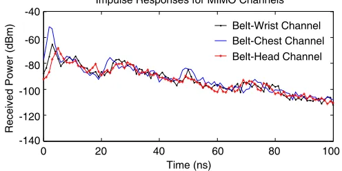
By applying an inverse Fourier transform to the measured frequency response (S21) values, the channel
impulse response is determined for the SISO channels and the MIMO sub-channels. In the MIMO configuration, the impulse responses were determined as the arithmetic mean of the four sub-channels’ impulse responses. From graphs presented in Fig. 5, the SISO impulse responses exhibit a stronger line of sight (LOS) component for the belt-chest channel (−48 dBm) compared to the belt-wrist channel (−61 dBm) and the belt head channel (−53 dBm), when−10 dBm is allocated to the transmitter power. This is mainly due to the direct visibility provided by the belt-chest channel. In the MIMO configuration, the belt-chest channel remains the strongest link with a−51 dBm received power, as illustrated in Fig. 6. It is observed that the deep fade is reduced in the MIMO results.
Belt-Wrist Channel Belt-Chest Channel Belt-Head Channel
Received Power (dBm)
-40
-60
-80
-100
-120
-140
0 20 40 60 80 100
Time (ns)
Impulse Responses for MIMO Channels
Figure 6. Impulse responses for the three On-body MIMO-M channels.
3.2. Ricean K-factor
The Rician K-factor is an indication of link quality [1, 16], measured as the relative strength of the direct and scattered components of the received signal, as expressed in the following equation [1]:
K(dB) = 10 log
A2
2σ2
(2)
whereAis the peak amplitude of the dominant component, andσ2 refers to the variance of the channel impulse responseh(t).
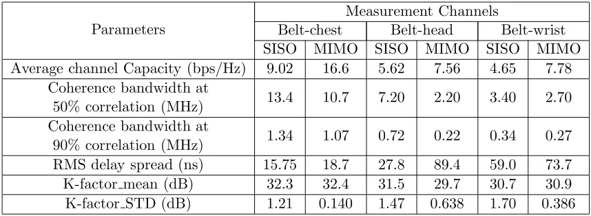
Table 1. Parameters values for each channel.
Parameters
Measurement Channels
Belt-chest Belt-head Belt-wrist
SISO MIMO SISO MIMO SISO MIMO
Average channel Capacity (bps/Hz) 9.02 16.6 5.62 7.56 4.65 7.78 Coherence bandwidth at
50% correlation (MHz) 13.4 10.7 7.20 2.20 3.40 2.70 Coherence bandwidth at
90% correlation (MHz) 1.34 1.07 0.72 0.22 0.34 0.27 RMS delay spread (ns) 15.75 18.7 27.8 89.4 59.0 73.7
K-factor mean (dB) 32.3 32.4 31.5 29.7 30.7 30.9
K-factor STD (dB) 1.21 0.140 1.47 0.638 1.70 0.386
3.3. RMS Delay Spread and Coherence Bandwidth
The RMS delay spread quantifies the time dispersive properties of a multipath channel. It was derived from the measurements using the following formulas [13]:
τRMS =
τ2−τ¯2 (3)
The parameter ¯τ represents the mean excess delay and ¯τ2 the second moment of the power delay profile (PDP) [13].
¯ τ =
ka2ktk
ka2k =
kp(tk)tk
kp(tk)
(4)
The parameter p(tk) in Eq. (4) is the power of the kth path and tk is its corresponding delay. The parameter a2k is the overall time average of the squared magnitude of the impulse response (6 measurements are averaged for such calculation).
The coherence bandwidth is inversely proportional to the RMS delay spread and measures statistically the range of frequencies over which the channel can be considered flat [13]. It was calculated for a 50% correlation using the following approximation [13]:
Bc 5τ1 RMS
(5)
Results show values of the RMS delay spread for the SISO channels in the rage of 15 ns to 59 ns, which correspond to coherence bandwidth (at 50% correlation) in the range of 3 MHz to 13 MHz as shown in Table 1. The MIMO RMS delay spread results, denoted in Table 1, are a little higher than the corresponding SISO results. This is due to the fact that the MIMO setup is able to collect more multipath components than the SISO setup.
3.4. Channel Capacity
The channel capacity is a measure of the theoretical maximum data rate per unit of bandwidth that can be reliably transmitted through a certain channel [17]. SISO channel capacity is derived from measurements using the following Shannon equation [18]:
CN[bps/Hz] = log21 +ρ|H|2 (6)
whereH is the normalized channel response and ρthe average signal to noise ratio (SNR).
The MIMO channel capacity (shown in Fig. 8) was also derived using the following equation [14]:
CMIMO
bps
Hz = log2
det
5 6 7 8 9 10 Capacity (bps/Hz)
0.4
0.2
0
Probability (capacity<abscissa)
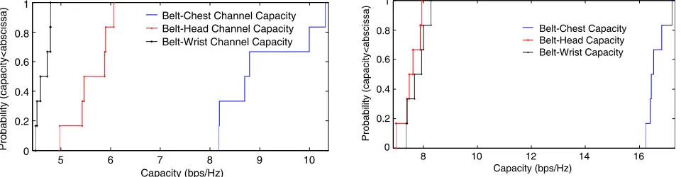
Figure 7. SISO capacity CDFs for the three On-body channels.
8 10 12 14 16
Capacity (bps/Hz) 0.4
0.2
0
Probability (capacity<abscissa)
Figure 8. MIMO capacity CDFs for the three On-body channels assuming a fixed transmitted power.
where H is the normalizedm×n channel response (m≥n), SNRav the average signal to noise ratio, and * the complex conjugate transpose. TheH matrix is normalized such that at each realization, the square of its Frobeinius norm is equal to the product of its dimensions (H2F =nm) [19, 20].
The results show that the channel capacity for a channel with a strong line of sight (LOS) component (belt-chest channel) is higher than the other channels with less strong LOS components. This result is valid for the average channel capacity (in Table 1) and for the CDF plots at a certain probability level (in Fig. 7 and Fig. 8). This is expected since a strong LOS component would result in a higher received power magnitude, and hence a higher SNR value. Detailed results for the average channel capacities of the SISO and MIMO channels are listed in Table 1.
They show a clear improvement of the channel capacity due to the use of MIMO. This improvement depends on the number of multi-path’ components and the strength of the LOS signal; hence, the Belt-wrist channel experienced an increase in capacity of about 3.1 bps/Hz and the Belt-chest channel capacity is improved by about 7.6 bps/Hz, due to the use of MIMO.
3.5. Channel Capacity for a Constant SNR
When the SNR is fixed, the effect of the multipath richness can be directly observed in the capacity CDFs and average values. In this case, the capacity includes only the effect of the multipath richness isolating the path loss effect. Therefore, this section deals with the capacity calculations using Eqs. (6) and (7) assuming a constant SNR. The CDF plots in Fig. 9 assume a SNR value of 20 dB, which was chosen large enough to guarantee that noise will not mask the results. These MIMO capacity CDFs show that at a constant SNR and for a probability level less than 80%, the belt-chest channel exhibits the highest capacity followed by the belt-head channel. Furthermore, the average MIMO capacity curves as a function of SNR emphasize this result as denoted by Fig. 10. For a SNR of 20 dB, the belt-chest average capacity is 10.9 bps/Hz, the belt-head capacity is 9.48 bps/Hz and belt-wrist capacity is 7.95 bps/Hz. It seems that the sub-channels correlation is significantly reduced due to the creeping-wave propagation which reduces the direct ray power, as explained in [14]. Moreover, the belt-chest and the belt-head channels exhibit similar multipath phenomena, probably because TX and RX are directly facing each other, in both channels. The chest capacity is slightly higher than the belt-head capacity, probably due to the fact that the main reflections from the walls and body parts are somewhat higher for the belt-chest channel. In the case of the belt-wrist channel, TX and RX main beams are pointing in different directions with the wrist mounted RX at a lower position than TX due to the length of the human subject arm (as represented in Fig. 2). Hence, the multipath propagation is mainly due to the reflections from the walls and ceiling, since the creeping wave and body reflections will likely be directed away from RX. Moreover, the CDF curves denote less spread in capacity for the belt-chest channel. This can be explained by the minor variations of the received powers for the belt-chest channel due to the fixed TX-RX distance.
8 9 10 10.5 11 Belt-Wrist Capacity Belt-Chest Capacity Belt-Head Capacity Capacity (bps/Hz) 0.8 1 0.6 0.4 0.2 0 Probability (capacity<abscissa) 8.5 9.5
Figure 9. MIMO capacity CDFs for the three On-body channels assuming a fixed SNR.
Belt-Wrist Capacity Belt-Chest Capacity Belt-Head Capacity
Channel Capacity vs SNR
5 10 15 20
SNR Values (dB) 12 10 8 6 4 2
Average Channel Capacity (bps/Hz)
Figure 10. MIMO average capacity as a function of SNR for the three On-body channels.
forN×N MIMO channel, the capacity is increasedN times for a fixed SNR level [21]. In this case, the throughput gain is less than 2 for all On-body channels due to some degree of correlation between the sub-channels. This throughput gain is found to be 1.6 for the belt-chest channel, 1.4 for the belt-head channel, and 1.2 for the belt-wrist channel. Hence, it can be concluded that the multipath richness is a significant factor in the capacity improvement.
4. DYNAMIC CHANNEL PARAMETERS’ RESULTS
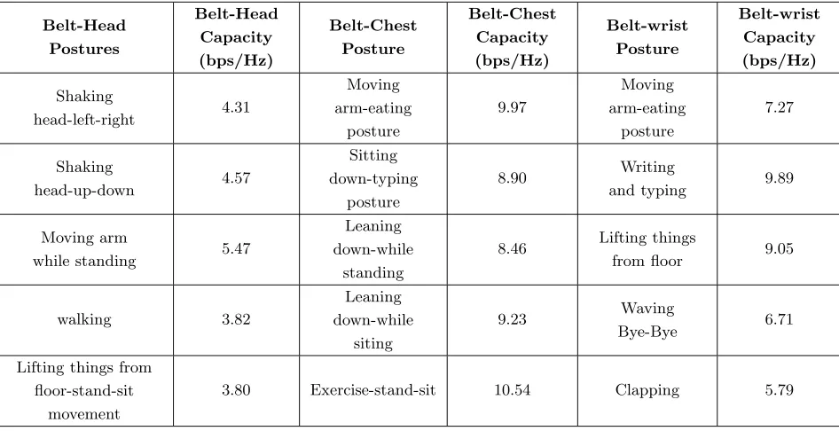
In addition to the measurement for a quasi-static channel, measurements were performed with different sets of movements for the three channels (Belt-Head, Belt-Chest, and Belt-wrist). The activity sets, and the corresponding capacity results for the three channels are given in Table 2. The results show that the movement of the human body has a minor effect on the capacity. This is clearly demonstrated by comparing the capacity results for a movement where theTX-RX length remains somewhat constant
Table 2. SISO capacity corresponding to typical states of the human body.
Belt-Head Postures Belt-Head Capacity (bps/Hz) Belt-Chest Posture Belt-Chest Capacity (bps/Hz) Belt-wrist Posture Belt-wrist Capacity (bps/Hz) Shaking head-left-right 4.31 Moving arm-eating posture 9.97 Moving arm-eating posture 7.27 Shaking head-up-down 4.57 Sitting down-typing posture 8.90 Writing
and typing 9.89
Moving arm
while standing 5.47
Leaning down-while
standing
8.46 Lifting things
from floor 9.05
walking 3.82 Leaning down-while siting 9.23 Waving Bye-Bye 6.71
Lifting things from floor-stand-sit
movement
results are expected, since the speed at which the receiver moves with respect to the transmitter is negligible compared to the speed of light, making the observed frequency at the receiver (including the Doppler’s effect), effectively the same as the emitted frequency. The channels are still effectively considered quasi-static. Table 2 represents the capacity values of the different On-body channels when the human subject undergoes certain typical body movements.
5. CONCLUSION
The significance of using MIMO for On-body channels in underground mines has been demonstrated through measurements for a 2 ×2 MIMO link. Three On-body channels have been considered for 2.45 GHz measurements. When a constant transmitted power is assumed, the channel capacity is highest for the belt-chest channel due to the smallTX-RX separation and rich multipath phenomenon. The k-factor results are correlated to the capacity values at a constant transmitted power. These values reflect the multipath richness and the presence of a strong LOS component, which also explains the RMS delay spread results. The belt-chest channel, due to its strong direct ray, exhibits the smallest RMS delay spread value. The RMS delay spread values are higher for the MIMO setup compared to SISO because the MIMO setup is able to collect more multipath components than SISO. The capacity results for a fixed SNR suggest that the sub-channels correlation is significantly reduced due to the creeping-wave propagation which reduces the direct ray power. Furthermore, the capacity results — for certain typical body movements — reflect the TX-RX separation regardless of the body motions. This performance study allowed concluding that MIMO technology is a suitable candidate for on-body underground communications. Such communication systems can indeed improve the security and the productivity of the miners.
REFERENCES
1. Khan, I., “Diversity and MIMO for body-centric wireless communication chan-nels,” PhD thesis report, University of Birmingham, Sep. 2009, [Online], available: http://etheses.bham.ac.uk/433/1/Khan09PhD.pdf.
2. El-Azhari, M. E., M. Nedil, I. B. Mabrouk, and L. Talbi, “Off-body channel characterization at 2.45 GHz in underground mine environment,” Proc. IEEE Antennas and Propagation Society Int.
Symp. (APSURSI), 251–252, Jul. 6–11, 2014.
3. El Azhari, M., M. Nedil, I. B. Mabrouk, K. Ghanem, and L. Talbi, “Characterization of an off-body channel at 2.45 GHz in an underground mine environment,”Progress In Electromagnetics Research M, Vol. 43, 91–100, 2015.
4. El Azhari, M., M. Nedil, and I. B. Mabrouk, “Performance evaluation of a SISO on-body system in underground mine environment,” 2014 IEEE Antennas and Propagation Society International
Symposium (APSURSI), 249–250, Jul. 6–11, 2014.
5. El Azhari, M. E., M. Nedil, and I. B. Mabrouk, “Characterization of an on-body quasi-static channel in underground mine environment,” 2015 IEEE Antennas and Propagation Society International
Symposium (APSURSI), Jul. 18–25, 2015.
6. Huan, L. B. and K. Hamaguchi, “A prototype BAN for medical and healthcare monitoring based on high band UWB,” 2011 14th International Symposium on Wireless Personal Multimedia
Communications (WPMC), 1–5, Oct. 3–7, 2011.
8. Nechayev, Y. I., P. S. Hall, C. C. Constantinou, Y. Hao, A. Alomainy, R. Dubrovka, and C. G. Parini, “On-body path gain variations with changing posture and antenna position,” 2005
IEEE Antennas and Propagation Society International Symposium (APSURSI), Vol. 1B, 731–734,
Jul. 3–8, 2005.
9. Brizzi, A., A. Pellegrini, L. Zhang, and Y. Hao, “Accuracy of asymptotic techniques for on-body channel characterization at W band,”2014 IEEE MTT-S International Microwave Workshop Series
on RF and Wireless Technologies for Biomedical and Healthcare Applications (IMWS-Bio), 1–3,
Dec. 8–10, 2014.
10. Nechayev, Y. I. and P. S. Hall, “Multipath fading of on-body propagation channels,” 2008 IEEE
Antennas and Propagation Society International Symposium (APSURSI), 1–4, Jul. 5–11, 2008.
11. Ahsanuzzaman Md Tariq, S., C. Despins, S. Affes, and C. Nerguizian, “Rough surface scattering analysis at 60 GHz in an underground minegallery,” 2014 IEEE International Conference on
Communications Workshops (ICC), 724–729, Jun. 2014.
12. Mabrouk, I. B., L. Talbi, M. Nedil, Y. Coulibaly, and T. A. Denidni, “Effect of antenna directivity on performance of MIMO systems in an underground gold mine,”IET Proc. Microwaves, Antennas &Propagation, Vol. 6, No. 5, 555–561, Institution of Engineering and Technology (IET), Apr. 2012. 13. Rappaport, T. S., “Mobile radio propagation: Small scale fading and multipath,” Wireless
Communications: Principle and Practice, 2nd Edition, Prentice Hall, 2001.
14. Khan, I. and P. S. Hall, “Experimental evaluation of MIMO capacity and correlation for narrowband body-centric wireless channels,”IEEE Transactions on Antennas and Propagation, Vol. 58, No. 1, 195–202, Jan. 2010.
15. Benmabrouk, I., L. Talbi, M. Nedil, and K. Hettak, “MIMO-UWB channel characterization within an underground mine gallery,” IEEE Transactions on Antennas and Propagation, Vol. 60, No. 10, 4866–4874, Oct. 2012.
16. Tepedelenlioglu, C., A. Abdi, and G. Giannakis, “The ricean k factor: Estimation and performance analysis,”IEEE Transactions on Wireless Communications, Vol. 2, No. 4, 799–810, 2003.
17. Lee, W. C. Y., “Estimate of channel capacity in Rayleigh fading environment,”IEEE Transactions
on Vehicular Technology, Vol. 39, No. 3, 187–189, Aug. 1990.
18. Hakan, I., “Multiple-input multiple-output system capacity: Antenna and propagation aspects,”
IEEE Antennas and Propagation Magazine, Vol. 55, No. 1, 253–273, Feb. 2013.
19. Carrasco, H., R. Feick, and H. Hristov, “Experimental evaluation of indoor MIMO channel capacity for compact arrays of planar inverted-F antennas,” Microw. Opt. Technol. Lett., Vol. 49, No. 7, 1754–1756, Jul. 2007.
20. Svantesson, T. and J. Wallace, “On signal strength and multipath richness in input multi-output systems,”Proc. IEEE Int. Conf. on Commun., Vol. 4, 2683–2687, May 2003.
21. Biglier, E., R. Calderbank, A. Constantnides, A. Goldsmith, A. Paulraj, and H. V. Poor, MIMO