Copyright to IJIRSET www.ijirset.com 2024
VIBRATION ANALYSIS OF CRITICAL
COMPONENTS OF PLAIN WEAVING
MACHINE
Prof. Rahul R.Joshi
1, Prof (Dr) V.R.Naik
2Assistant professor, Department of Mechanical Engineering, DKTE’S Textile and Engineering Institute,
Ichalkaranji, Maharashtra, India 1
Professor and Head of mechanical Department, DKTE’S Textile and Engineering Institute, Ichalkaranji, Maharashtra,
India 2
Abstract: This paper reports on an investigation in to the feasibility of using active and passive means of vibration control i.e. by using analysis and chemical coating method in Plain weaving machine. Noise is major criteria in textile industry hence by considering government norms and human health, consider a critical mechanism which produces more noise and vibration. In this paper the observed mechanism is picking mechanism with shaft and cam which gives meshing details, force analysis, Teflon chemical coating with reduction in noise and vibration results and its feasibility and FFT analyser results.
.
Keywords: Force analysis, Control of vibration, Teflon coating, FFT analyser
I. INTRODUCTION
Any motion that repeats itself after an interval of time is called vibration. Vibration of system involves transformation of kinetic energy and potential energy. The fundamentals of vibration analysis can be understood by studying the simple mass–spring–damper model. Even a complex structure such as an automobile body can be modelled as a "summation" of simple mass–spring–damper models. [1]
The mass–spring–damper model is an example of a simple harmonic oscillator. The mathematics used to describe its behaviour which is identical to other simple harmonic oscillators such as the circuit. Two typical types of vibration tests performed are random and sine test. Sine (one-frequency-at-a-time) tests are performed to survey the structural response of the device under test. A random (all frequencies at once) test is generally considered to more closely replicate a real world environment. The problems of noise in the industries are very critical. While considering human health and government norms machine should have maximum sound up to sustainable level. Generally Plain weaving machine produces sound up to 90 dBA.[2]
II. CONTROLOFVIBRATION[3][4]
1) By controlling the natural frequencies of the system and avoiding resonance under excitations 2) By introducing a damping or energy dissipating mechanism
3) By reducing the transmission of excitation forces from one part to another part 4) By reducing response of the machine
III.NECESSARYEQUIPMENTSFOR EXPERIMENTALMODALANALYSIS
1) An exciter or source of vibration to apply a known input force to the machine 2) A transducer to convert the physical motion of the structure in to electronic signal
3) A signal conditioning amplifier to make the transducer characteristics compatible with the input electronics of the digital acquisition system.
Copyright to IJIRSET www.ijirset.com 2025
IV.METHODOLOGYOFWORKISDIVIDEDINTOFOLLOWINGSECTIONS.
1) Measure noise and vibration
Measure the noise of machine from all four directions, away from 1 meter of machine. Noise of the machine can measure at different loading condition and at no load condition.
2) Locate the mechanism which produces more noise and vibration.
Generally machine produces more noise at full load. Segregate and locate the mechanism which produces more noise and vibration.
3) formulate mathematical model of given data.
4) Analysis of both noise and vibration of located mechanism.
5) Design or modify the located mechanism. From mathematical model, analysis results we will predict about optimum material of subcomponent or subassemblies. This optimum material will give less vibration hence noise production is also reduces
V. MESHINGANDANALYSISOFCRITICALCOMPONENTSOFPLAINWEAVINGMACHINE
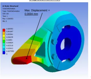
Main parts of picking mechanism are cone (cast iron, MS, Nylon) , picker (Nylon) , bowl (cast iron) , shaft( wood). By considering feasibility of manufacturing cone has been selected for static and dynamic analysis. Approximate weight of its 500 gram, RPM for the same is 60.
Displacement Plot
6
Max. Displacement = 0.0694 mm
Figure 1: Bowl analysis
Displacement Plot
18
Max. Displacement = 0.01224 mm
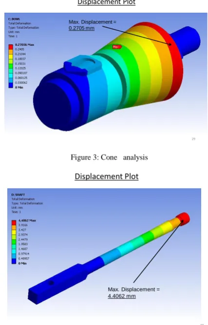
Copyright to IJIRSET www.ijirset.com 2026 Displacement Plot
29 Max. Displacement =
0.2705 mm
Figure 3: Cone analysis
Displacement Plot
40 Max. Displacement =
4.4062 mm
Figure 4: Shaft analysis
7
Copyright to IJIRSET www.ijirset.com 2027
VI.CHEMICALCOATING
after finishing the static and dynamic analysis we can predict about critical portion of subassembly. So to reduce noise and vibration chemical coating is the one of the best method. Teflon coating is done on the critical component. Up to the three layers coating has been done.
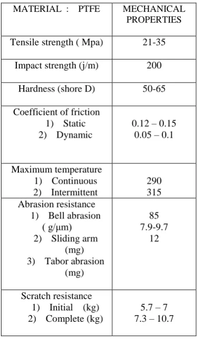
MATERIAL : PTFE MECHANICAL PROPERTIES
Tensile strength ( Mpa) 21-35
Impact strength (j/m) 200
Hardness (shore D) 50-65
Coefficient of friction 1) Static 2) Dynamic
0.12 – 0.15 0.05 – 0.1
Maximum temperature 1) Continuous 2) Intermittent
290 315 Abrasion resistance
1) Bell abrasion ( g/μm) 2) Sliding arm
(mg) 3) Tabor abrasion
(mg)
85 7.9-9.7
12
Scratch resistance 1) Initial (kg) 2) Complete (kg)
5.7 – 7 7.3 – 10.7
Table 1: Properties of Material
VII. EXPERIMENTRESULTOFCHEMICALCOATINGWITHFFTANALYZER
SR NO
STAINLESS STILL
RECORD FILE Noise Vibration
Half load 89 231 SSNCH
Full load 90.3 210 SSNCF
Copyright to IJIRSET www.ijirset.com 2028 SR
NO
COAT
1
COAT
2
RECORD FILE
Noise Vibration Noise Vibration
Half load
87.7 230 87.6 137 SSHL 1,2
Full load
90.1 234 90.4 201 SSFL 1,2
Table 3: Stainless Still with Coating
0 2 4 6 8 10 12 14 16 18 20
[Hz] 0.4
0.8 1.2 1.6
2 Cursor values
X: 7.200 Hz Y: 0.456 m/s²
Autospectrum(1 Scalar,) (Magnitude) \ FFT
Graph1: FFT Analyser Curve (Before Coating)
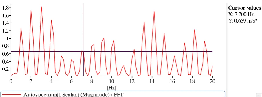
0 2 4 6 8 10 12 14 16 18 20
[Hz] 0.2
0.4 0.6 0.8 1 1.2 1.4 1.6
1.8 Cursor values
X: 7.200 Hz Y: 0.659 m/s²
Autospectrum(1 Scalar,) (Magnitude) \ FFT
Copyright to IJIRSET www.ijirset.com 2029 VIII. CONCLUSION
Modal testing and structural dynamics testing in general has been concentrating on the determination of modal frequencies, mode shapes and modal damping. In this paper, static and dynamic analysis of critical subassemblies gives different stress zone areas. By considering this data it is possible to choose component and which type of coating with how many layers are required. Performance of chemical coating for vibration and noise reduction is depends on different layers of Teflon coating. It is evaluated by FFT analyser. There is reduction in noise and vibration after coating on stainless still cone.
REFERENCES
[1]Hansen CH, Snyder SD (1997) Active Control of Noise and Vibration. E & FN Spon, London
[2]Y.N.Zhang,J.Yang, C.C.,X.H.Tang, Research and application of damping material, “Noise and Vibration Control” (2006) 38–41
[3]J.W. Cooley, J.W. Tukey, “An algorithm for the machine calculation of complex Fourier series, Mathematics of Computation” (1965). 520-539
[4]Z.Y. Ping, H.S. Hong, H.J. Hong, S. Tao, L. Wei, “Continuous wavelet grey moment approach for vibration analysis of rotating machinery, Mechanical Systems and Signal Processing” (2006) 1202–1220.
[5] M. Feldman, S. Seibold, “Damage diagnosis of rotors: application of Hilbert transform and multihy pothesis testing”, Journal of Vibration and Control 5 (1999) 421–442.
[6]K.F. Martin, “A review by discussion of condition monitoring and fault-diagnosis in machine-tools, International Journal of Machine Tools and Manufacture”(1994) 527–551.
[7] C. Davies, R.M. Greenough, The use of information systems in fault diagnosis, in: Proceedings of the 16th National Conference onManufacturing Research, University of East London, UK, 2000.
[8]Melnick, w. Hearing loss from noise exposure, Handbook of Noise Control, Harris, C. M (Ed.). Mc. Grow Hill, New York, 450-481 [9] Richards”Noise considerations in machines and factories", Chart. Mech. Eng, 123-129
[10] F. Al-Badour, L. Cheded, B. Isayed, “Vibration monitoring and fault detection using time-frequency techniques”, in: 4th IEEE International Multi- Conference on Systems, Signals and Devices SSD07, Hamamet, Tunisia. (2007).