Indirect Vector Controlled Induction Motor
Drive for High Performance Using Fuzzy
Logic
S. Sentil KumarAssistant professor, Department of Electronics and Instrumentation, Bharath University, Chennai, India
ABSTRACT: Fuzzy logic speed control system based on fuzzy logic approach for an indirect vector controlled
induction motor drive for high performance. The analysis, design and simulation of the fuzzy logic controller for indirect vector control induction motor are carried out based on fuzzy set theory. The proposed fuzzy controller is compared with PI controller with no load and various load condition. The result demonstrates the robustness and effectiveness of the proposed fuzzy controller for high performance of induction motor drive system.
I. INTRODUCTION
Ac motor drives are extensively used in industrial application requiring high performance. In high performance system, the motor speed should closely follow a specified reference trajectory regardless of any load disturbance, parameter variations and model uncertainties. In order to achieve high performance, field-oriented control of induction motor drive is employee. However the control design of such a system plays a role in system performance. The decoupling characteristics of vector-controlled induction motor are adversely affected the parameter changes in the motor.
The speed control of IM issues are traditionally handled by fixed gain PI and PID controllers. However the fixed gain controllers are very sensitive to parameter variations, load disturbances etc. Thus, the controller parameters have to be continuously adapted. The problem can be solved by several adaptive control techniques such as model reference adaptive control, sliding mode control smc, variable structure control VSC and self tuning PI controller etc. The design of the entire above controller depends on the exact system mathematical model. However it is often difficult to develop a accurate mathematical model due to unknown load variation and unavoidable parameter variations due to saturation, temperature variations and system disturbance. To overcome the above problems, Fuzzy logic controller (FLC) is being used for motor control purpose. There is some advantage of fuzzy logic controller as compared to conventional PI, PID and adaptive controller such as it does not require any mathematical model, it is based on linguistic rules within IFTHEN general structure, which is the basic of the human logic.
II. LITERATURE REVIEW 2.1 Scalar control
The name scalar control indicates the magnitude variation of control variables only. The control of an induction motor requires a variable voltage variable frequency power source. With advent of the voltage source inverter (VSI), constant voltage/hertz (V/f) control has become the simplest, cheapest and hence one of the popular methods for speed control of induction motor.
Scalar control drives were widely used in industry, because it is simple to implement. But inherently there exists a coupling effect between both flux and torque (both are function of voltage or current and frequency), which gives sluggish response and the system becomes prone to instability. The importance of scalar control drives has diminished now a day because of the superior performance of the vector controlled drives.
2.2 Vector control
By splitting the stator current into two orthogonal components, one in the direction of flux linkage, representing magnetizing current or flux component of current, and other perpendicular to the flux linkage, representing the torque component of current, and then by varying both components independently, the induction motor can be treated as a separately excited DC motor. This concept was invented in the beginning of 1970s. The implementation of vector control requires information regarding the magnitude and position of the flux vector.
Depending upon the method of acquisition of flux information, the vector control or field oriented control method can be termed as: direct or indirect. In the direct method the position of the flux to which orientation is desired is strictly measured with the help of sensors, or estimated from the machine terminal variables such as speed and stator
current/voltage signals. The measured or estimated flux is used in the feedback loop, thus the machine parameters have minimal effect on the overall drive performance. But the measurement of flux using flux sensors necessitates special manufacturing process or modifications in the existing machines. Also direct field orientation method has its inherent problem at low speed where the voltage drops due to resistances are dominant, and pure integration is difficult to achieve.
The indirect vector control was originally proposed, eliminates the direct measurement or computation of rotor flux from the machine terminal variables, but controls its instantaneous flux position by summing the rotor position signal with a commanded slip position signal (also known as slip frequency control or feed forward control scheme). The direction of rotor position needs an accurate rotor speed information and the commanded slip position is calculated from the model of the induction motor, that again involves machine parameters which may vary with temperature, frequency and magnetic saturation. To get ideal decoupling, the controller should track the machine parameters and for this various adaptation methods have been proposed. However it has been reported that the controller performance is 10 adequate within normal operating temperatures for most of the high performance applications, and the parameter adaptations methods may be essential only in the case of critical applications. In contrast to direct method the indirect method controls the flux in an open loop manner. Field orientation scheme can be implemented with reference to any of the three flux vectors: stator flux, air gap flux and rotor flux. It has been shown that out of the three the orientation with respect to rotor flux alone gives a natural decoupling between flux and torque, fast torque response and better stability. Hence in this work orientation along rotor flux is considered.
2.3 Flux Observer and speed Estimation
There are many techniques involved in implementing different types of field oriented control. Most of the methods require precise estimation of either the rotor position or speed. This implies the need for speed sensors such as shaft mounted tacho-generators or digital shaft encoders. The speed sensors increase the cost and size of the drive, lower the system reliability, and also require special attention to measure noise. Some methods (direct field orientation) require the rotor flux, which is measured using Hall Effect sensors or search coils. The Hall Effect sensors degrade the performance and reliability of the drive system. The estimation of rotor flux by integration of the open loop machine voltages arise difficulties at low speed.
Recently, substantial research efforts have also been devoted to intelligent controllers such as artificial neural networks (ANN) and fuzzy logic to deal with the problems of nonlinearity and uncertainty of system parameters. The fundamental characteristics of neural networks are: ability to produce good models of nonlinear systems; highly distributed and paralleled structure, which makes neural-based control schemes faster than traditional ones; simple implementation by software or hardware; and ability to learn and adapt to the behavior of any real process. On the other hand it was shown that fuzzy controllers are capable of improving the tracking performance under external disturbances, or when the IFO drive system experiences imperfect decoupling due to variations in the rotor time constant. Neural network and fuzzy logic are gaining potential as estimators and controllers for many industrial applications, due to the fact that they posses better tracking properties than conventional controllers.
2.4 Necessity of a robust controller
adaptation of parameters to achieve decoupling is possible, but very difficult and complex process. To reduce effects of rotor parameter variations, various on-line tuning techniques.
A robust control technique is a good solution for the rotor parameter detuning problem. In addition to the above problem, there are also other problems associated with induction motor drives which necessitate a robust control technique. These are load torque disturbances, approximations in the model used in analysis and design of the controller, and necessity to track complex trajectories, not only step changes. Under these conditions a robust control technique is essential. Sliding Mode is one such control technique.
2.5 Sliding Mode Controller
Sliding mode controller is suitable for a specific class of nonlinear systems. This is applied in the presence of modeling inaccuracies, parameter variation and disturbances, provided that the upper bounds of their absolute values are known. Modeling inaccuracies may come from certain uncertainty about the plant (e.g. unknown plant parameters), or from the choice of a simplified representation of the system dynamic. Sliding mode controller design provides a systematic approach to the problem of maintaining stability and satisfactory performance in presence of modeling imperfections. The sliding mode control is especially appropriate for the tracking control of motors, robot manipulators whose mechanical load change over a wide range. Induction motors are used as actuators which have to follow complex trajectories specified for manipulator movements. Advantages of sliding mode controllers are that it is computationally simple compared adaptive controllers with parameter estimation and also robust to parameter variations. The disadvantage of sliding mode control is sudden and large change of control variables during the process which leads to high stress for the system to be controlled. It also leads to chattering of the system states.
Soto and Yeung and Utkin have applied sliding mode control to induction motor drive. In sliding mode control methods are applied to an indirect vector controlled induction machine for position and speed control. It is also applied to position control loop of an indirect vector control induction motor drive, without rotor resistance identification scheme. A sliding mode based adaptive input output liberalizing control is presented in for induction motor drives. In this case the motor flux amplitude and speed are separately controlled by sliding mode controllers with variable switching gains. A sliding mode controller with rotor flux estimation is presented in for induction motor drives. Rotor flux is also estimated using a sliding mode observer. Although many speed estimation algorithms and sensor less control schemes are developed during the past few years, development of a simple, effective and low sensitivity speed estimation scheme for a low power IM drive is lacking in the literature. Sliding mode controller is a good choice for handling this type of problems.
Graphical interpretation of equation
III. RESEARCH METHODOLOGY
The following presents the outline of the work in details.
Presents a review on the available literature on scalar control and vector control stating their limitations. Various types of observer and speed estimation scheme are also described. The application aspect of sliding mode controller to induction motor drive is also presented. Lastly it sets forth the objectives of the present work and outlines the organization of the thesis. Modeling of induction motor is discussed. The differential equations of the motor are expressed in synchronously rotating (d- q) reference frame with stator current and rotor flux components as state variables. The developed torque is used as a state variable in place of q- axis stator current. The drive system is transformed to two linear and decoupled subsystems; electrical and mechanical. There are two PI controllers for the mechanical subsystem and one for the electrical.
A reduced order rotor flux observer has been designed to estimate rotor flux. This observer estimates both the components of rotor flux in the synchronous reference frame. But the q-axis flux linkage is zero at the steady state and nearly zero during transients. So its computation is not needed and a simpler observer for estimating only the d-axis rotor flux is developed. The computation needed is decreased and thus preferable for real time estimation. A simple, effective and low sensitivity speed estimation technique has been proposed for the drive is described here. The speed is calculated from the estimated stator flux linkage components in the stationary reference frame. Development of a sliding mode controller for robust control of induction motor drive under model inaccuracy, load disturbances and parameter variations is described.
The theory of sliding mode control is briefly reviewed and control law is derived. The controller gain and band width are determined considering various factors, such as rotor resistance variation, model inaccuracy and load disturbances to have an ideal speed tracking. The control law is modified to reduce the chattering of the control input and states. The width of the boundary layer, introduced for this purpose, is determined to reduce chattering as well as to keep the tracking error at its minimum value.
3.1 Induction Motor Modeling
Although construction of induction motor is simple, its speed control is considered to be far more complex than that of DC motors. The reason is nonlinear and highly interacting multivariable state space model of the motor. The rapid and revolutionary progress in microelectronics and variable frequency static inverters with application of modern control theory has made it possible to build sophisticated controllers for AC motor drives. The design and development of such drive system require proper mathematical modeling of the motor to optimize the controller structure, the inputs needed and the gain parameters. In this chapter the modeling of induction motor is presented.
A proper model for the three phase induction motor is essential to simulate and study the complete drive system. The model of induction motor in arbitrary reference frame is derived.
Following are the assumptions made for the model:
1. Each stator winding is distributed so as to produce a sinusoidal mmf along the airgap, i.e. space harmonics are negligible.
2. The slotting in stator and rotor produces negligible variation in respective inductances. 3. Mutual inductances are equal.
4. The harmonics in voltages and currents are neglected. 5. Saturation of the magnetic circuit is neglected.
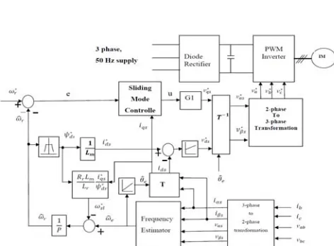
Fig. 1 Induction motor drive system with sliding mode controller
3.2 DESIGN OF FUZZY LOGIC CONTROLLER FOR INDUCTION MOTOR DRIVE
Fig. 2 shows block diagram of speed control system using fuzzy logic controller
Here the first input is the speed error ‘e’ and second is the change in speed error ‘ce’ at sampling time ‘ts’. The two input variables e(ts) and ce(ts) are calculated at every sampling time as
Fig.2 Functional block diagram of Fuzzy Logic Control
Fig.3 Fuzzy Logic Controller Internal structure
A. Fuzzifications:
In this stage the crisp variables of input e(ts) and ce(ts)are converted into fuzzy variables. The fuzzification maps the error and change in error to linguistic labels of fuzzy sets.
B. Knowledge base and inference stage:
Knowledge base involves defining the rules represented as IF-THEN rules statements governing the relationship between input and output variables in terms of membership function. In this stage the input variables e(ts)and ce(ts)are processed by the inference mechanism that executes 7*7 rules represented in rule table shown below. Considering the first rule, it is represented as IF change in speed error is NB and change in speed is NB, THEN the output will be NB Here Mamdani’s algorithm for inference mechanism used.
C. Defuzzification:
This stage introduces different methods that can be used to produce fuzzy set value for the output fuzzy variable ΔT. Here the centre of gravity or centroids method is used to calculate the final fuzzy value ΔT(ts).Defuzzification using COA method means that crisp output of ΔT*(ts) is obtained by using centre of gravity, in which the crisp output ΔT(ts) variable is taken to be the geometric centre of the output fuzzy variables value μout(ΔT)area, where μout(ΔT) is formed by taking the union of all the contributions of rules with the degree of fulfillment greater than zero.
TABLE: 1 Fuzzy Controller Rule Base
IV. EXPERIMENTAL RESULTS AND DISCUSSION
The machine is initially at stand still with no load. The reference speed is linearly increased from zero its rated value 500 rpm with FLC and PI controller. Various simulations were carried out on both PI controller and fuzzy logic controller on the indirect-vector control of Induction motor. Fig.4 and fig.5 shows The PI and FLC with a step command of Speed are applied with no load condition. In case of PI Controller the rise time is in between ts=0.5 to ts=0.6 , but in case of FLC rise time is in between ts=0.3 to ts=0.4 .It is conclude that FLC offers faster response as compare to PI. Hence FLC based drive system is superior to PI based drive system in all respect rise time, settling time and overshoot. Fig. 6 and Fig. 7 shows the PI and FLC at load condition. Here the PI controller was affected by change in load, but FLC have no affect by the change in load. The proposed FLC is more robust to load disturbance as compared to PI controller.
Fig.5. Speed response of Fuzzy logic controller at no load
Fig.6. Speed response of PI controller at load
Fig.9. X-Y plot of Rotor flux of Fuzzy logic controller
V. CONCLUSIONS AND FUTURE WORK
In this fuzzy logic controller for the control of an indirect vector-controlled induction motor was described. The drive system was simulated with fuzzy logic controller and PI controller and their performance was compared. Here simulation results shows that the designed fuzzy logic controller realizes a good dynamic behavior of the motor with a rapid settling time, no overshoot and has better performance than PI controller. Fuzzy logic control has more robust during change in load condition.
The equations of the induction motor model are reorganized so as to apply the control technique. The controller gain and band width are designed, considering various factors such as rotor resistance variation, model in accuracies, load torque disturbance and also to have an ideal speed tracking. Considering the case such as load disturbance, the response of the designed sliding mode controller is satisfactory. It also gives good trajectory tracking performance. The speed regulation characteristic is also satisfactory.
Only load disturbance is the problem considered in this case and the robustness of the controller is verified. Since the machine rating is small, the resistance variation effect is very small. Hence has negligible effect. As a future work this controller can be applied to any other drive system with higher rating where parameter variation effect can be studied. Fuzzy logic Principle can be incorporated to this controller to make it more efficient and robust.
REFERENCES
[1] Bose B.K.,”Modern Power Electronics and AC Drives”, Pearson Education, 4th
Edition, 2004
[2] R.M. Cuzner, R.D. Lorenz, D.W. Novotny, “Application of non-linear observers for rotor position detection on an induction motor using machine voltages and currents,” IEEEIAS Annual Meeting Conference Record, October 1990, pp. 416–421.
[3] Atkinson D. J., P. P. Acarnley and J. W. Finch, “Application of estimation technique in vector controlled inductin motor drives,” IEE Conference Proceeding, London, July 1990, pp. 358-363.
[4] A. Ferrah, K.G. Bradely, G.M. Asher, “Sensorless speed detection of inverter fed induction motors using rotor slot harmonics and fast Fourier transform,” IEEE-PESC Conference Record, October 1992, pp. 279–286.
[5] Baader U., M. Depenbrock, and G. Gierse, “ Direct self control of inverter- fed induction machines: A basis for speed control without a speed measurement,” IEEE Trans. Ind. Appl., vol. 28, no. 3, May 1992, pp. 581-588.
[6] Blaschke F., “ The principle of field orientation as applied to the new TRANSVECTOR closed loop control system for rotating field machines,” Siemens Review, vol. 93, no. 5,may 1970, pp. 217-220.
[7] Chan, C. C., and H. Q. Wang, “New scheme of sliding mode control for high performance induction motor drives,” IEE Proc. on Electric Power Applications, vol. 143, no. 3, May 1996, pp 177- 185.
[8] Chan C. C., Leung W. S. and C. W. Nag, “ Adaptive decoupling control of induction motor drives,” IEEE Transaction on Industrial Electronics, vol. 35, no. 1, Feb. 1990, pp.41-47.
[9] N. Teske, G.M. Asher, M. Sumner, K.J. Bradely, “Suppression of saturation saliency effects for the sensorless position control of induction motor drives under loaded conditions,” IEEE Trans. Ind. Appl. 47 (5) (2000) 1142–1150.
[10] N. Teske, G.M. Asher, M. Sumner, K.J. Bradely, Encoderless position estimation for symmetric cage induction machines under loaded conditions, IEEE Trans. Ind. Appl. 37 (6) (2001) 1793–1800.
[11] Dunngan, M. W., S. Wade, B. W. Willams, and X. Xu, “Position control of a vector controlled induction machine using Slotine’s sliding mode control approach,” IEE Proc. on Elect. Power Appl., vol. 145, no. 3, May 1998, pp. 231- 238.
[12] Garces L. J., “Parameter adaptation for speed controlled static AC drives with a squirrel cage induction motor,” IEEE Trans. On Industry Applications, vol. 16, no. 12, Mar. 1980, pp 173 -178.
[14] Hung K. T., and R. D. Lorenz, “ A rotor flux error based adaptive tuning approach for feed forward field oriented induction machine drives,” IEEE Conf. record IAS annual meeting, 1990, pp. 594-598.
[15] Kim Y. R., S. K. Sul and M.H. Park, “ Speed sensorless vector control of induction motor using extended Kalman filter,” IEEE Transaction on Ind. Appl., Vol. 30, no. 5, 1994, pp. 1225-1233.
[16] Krause P. C., Analysis of Electric Machinary, McGrow-Hill, New York, 1986 [17] Krause P. C and C. S. Thomas, “Simulation of symmetrical induction machinery,” IEEE Trans. on Power Apparatus & Systems, vol. 84, no. 11, 1965, pp. 1038- 1053.
[18] Krishnan R. and A. S. Bharadwaj, “ A review of parameter sensitivity and parameter deviations in feed forward field oriented drive systems,” IEEE Transaction on power Electronics, vol.6, no. 4, 1991, pp. 695- 703.
[19] Mohanty K. B., A. Routray and N. K. De, “Rotor flux oriented sensor less induction motor drive for low power applications.” Proceeding of Int. Conference on Computer Application in Electrical Engg.: Recent Advances (CEERA), Feb, 2001, Roorkee, pp. 747- 752