Article
1
Improvement of the Torque-speed Performance and
2
Drive Efficiency in an SRM Using an Optimal
3
Torque Sharing Function
4
Wei Ye 1,*, Qishuang Ma 1 and Poming Zhang 1
5
1 School of Automation Science and Electrical Engineering, Beihang University, Beijing, China
6
* Correspondence: [email protected]; Tel.: +86-134-3976-4637
7
8
Abstract: In this paper, by evaluating extreme value of the qth-power current, a torque sharing
9
function (TSF) family for reducing the torque ripples in the switched reluctance motor (SRM) is
10
proposed. The optimization criteria of the TSF has two secondary objectives, including the
11
maximization of the torque-speed range and the minimization of copper loss. The evaluation indices
12
in terms of the peak phase current, the rms phase current, and the torque ripple factor are compared
13
between the proposed TSF family and four conventional TSFs including linear, sinusoidal,
14
exponential, and cubic TSFs. An optimization objective function that combines the maximum
15
absolute value of the rate-of-change of the flux linkage (MAV-RCFL) and the qth-power of current
16
is proposed and a weighting factor is used to balance the influence of the two optimization
17
objectives. An optimal TSF can be easily obtained by solving the optimization problem from the TSF
18
family. The proposed TSF is validated by using simulations and experiments with a three-phase 6/4
19
SRM with 7.5 kW, 3000 rpm, and 270 V DC-link voltage. The dynamic simulation model is
20
implemented in Matlab/Simulink. The results demonstrate the validity and superiority of the
21
proposed control method; the optimal TSF provides better torque-speed performance, and a better
22
reduction in copper loss and torque ripples at high speed compared to the conventional TSFs
23
obviously.
24
Keywords: switched reluctance motor (SRM); torque-speed performance; drive efficiency; torque
25
sharing function (TSF)
26
27
1. Introduction
28
Switched reluctance motors (SRM) are gaining interest in various applications such as electric
29
vehicle driving system, starter-generators system, and power supply for aerospace applications,
30
because the SRM has many advantages compared with other motors due to its low cost, durability,
31
simple structure and robust construction [1,2]. Due to advances in high speed digital signal
32
processing and power electronics technology, the controllable performance of the SRM has been
33
improved greatly. However, one of the main drawbacks of the SRM used in servo-control is its large
34
torque ripple, which leads to acoustic noise and vibration, thus cause the body vibration,
35
transmission system parts damaged, excessive bearings wear and even axis broken accidents [3,4].
36
There are two main methods to reduce the torque ripple: one is to optimize the structure and
37
magnetic design of the motor, and the other is to adopt the advanced control algorithm [5]. By
38
optimizing the stator/rotor pole structures and the magnetic design, the torque ripple cannot be fully
39
reduced but the cost of the motor increases [6]. The main operating parameters of an SRM include
40
the supply voltage, the turn-on and turn-off angles, the current level, and the shaft torque. And the
41
control algorithm is based on selecting an optimum combination of these parameters [7, 8]. Therefore,
42
an appropriate design for achieving a high SRM performance must take these factors into
43
consideration and make an optimal choice.
44
As an effective method for torque ripple reduction, direct instantaneous torque control (DITC)
45
gained interest during the last few years due to its simple control structure, which provides greater
46
flexibility for the torque ripple reduction [9-12]. However, its implementation is not easy because it
47
requires complex switching rules, uncontrolled switching frequency, and high sampling rates. In [9,
48
10], an iterative learning method for generating the optimized current waveforms was presented. In
49
[11, 12], an online DITC technique that operates without torque profile functions and auxiliary phase
50
commutating strategies was demonstrated. The optimal turn-on and turn-off angles for minimizing
51
the torque ripple or the energy consumption have been described in [13-15]. In [16], a direct torque
52
control based on the Lyapunov function was selected to minimize the torque ripples. In [17] and [18],
53
the machine design was combined with the control algorithms in an innovative method of profiling
54
the phase currents to reduce the torque ripples of an SRM.
55
The torque sharing function (TSF) is an important and effective approach for minimizing the
56
torque ripple in an SRM in the latest research [19-24]. Common TSFs curves contain linear, sinusoidal,
57
exponential, cubic curves, and so on. In order to reduce the torque ripple, the phase current product
58
the individual phase torque harmoniously using the most suitable TSFs so that the total torque can
59
be agreed with the expected torque. Subsequently, the phase torque reference can be translated into
60
the phase current reference based on the T-i-θ characteristics. With increasing speed of the SRM, the
61
phase current cannot ideally follow its reference because of the limited phase voltage and therefore
62
the torque ripples increase. In addition, because the phase current reference can be derived from the
63
phase torque reference, the choice of the TSF directly affects the copper loss and the current tracking
64
performance. The current tracking performance should be improved to enhance the torque-speed
65
capability. Thus, in order to obtain an optimum TSF, it is necessary to consider a secondary objective
66
that includes the maximization of the torque-speed range and the minimization of copper loss. These
67
two evaluation criteria affect the torque-speed performance and the drive efficiency of the motor. In
68
[19], four conventional common TSFs were studied and evaluated after optimization. In order to
69
minimize the rms (root mean square) phase current and the maximum absolute value of the
rate-of-70
change of the flux linkage (MAV-RCFL), the turn-on and the overlap angle were extracted based on
71
a genetic algorithm optimization method to select the optimal TSF. In [20], for reducing the losses of
72
the switched reluctance motors, a piecewise cubic TSF is optimized with six degrees of freedom. In
73
[21], an offline TSF with a wide torque-speed range for reducing torque ripple in an SRM was studied;
74
the objective function adopted a Tikhonov factor among two objectives to minimize the maximum
75
absolute value of RCFL and the copper loss. In [22], an extended-speed low-ripple torque control in
76
two modes using the TSF in an SRM was introduced. Because of the imperfect tracking of the phase
77
current in high motor speed, a proportional-integral controller with a torque-compensation was
78
added to the torque reference during the commutation range of two adjacent phases. In [23], a novel
79
and simple nonlinear logical TSF was proposed to reduce the torque ripple and improve the
80
efficiency. The logical TSF was used online and was not fixed compared with the other TSFs. The
81
incoming phase current was controlled in a ladder-like increase, and the current of the outgoing
82
phase was tracked in the opposite direction. Therefore, torque sharing between the incoming and
83
outgoing phases was achieved with a minimum current crossover. However, a theoretical analysis of
84
the RCFL was not provided for this study.
85
In this paper, taking into account the requirements for the maximization of the torque-speed
86
range and the minimization of copper loss and balancing these secondary objectives by including a
87
weighing factor, a family of TSFs deduced by an invertible torque function is proposed. Because the
88
proposed TSF provides phase currents throughout the whole region, the torque-speed capability is
89
improved as well. The solution of the TSFs selection becomes a muti-objective optimization problem.
90
And then, the evaluation indices such as the peak phase current, the rms phase current, and the
91
torque ripple factor are compared between the proposed and the classical TSFs by using a simulation.
92
Finally, the simulation and experimental results show that the proposed control algorithm has
93
advanced performance in reducing the copper loss and improving torque-speed performance.
2. The Finite Element Method Analysis for the SRM
95
The SRM only has stator windings. no rotor windings or magnets. The whole or part of each
96
phase is comprised of two stator windings on diametrically opposite sides of the SRM. A three-phase
97
6/4 SRM with 7.5kW, 3000rpm, and 270V DC-link voltage is designed (seen Table A1 in Appendix
98
A). Figure 1 (a-d) shows the analysis model of the studied motor using the finite element method
99
(FEM) with the magnetic flux at rotor positions of 0°, 15°, 30°, and 45° respectively. The anti-clockwise
100
is the positive direction of the rotor angular position θand the alignment position of the stator and
101
rotor poles is defined as 0°.
102
103
(a) (b) (c) (d)
104
Figure 1. The FEM analysis model of the SRM with the magnetic flux (I=8A): (a)θ=0°; (b)θ=15°; (c)θ=30°;
105
(d)θ=45°.
106
107
(a) (b) (c)
108
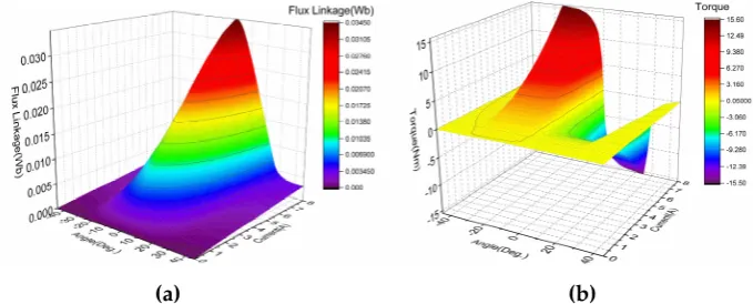
Figure 2. The phase inductance, the flux linkage profiles and the torque characteristics of the studied SRM: (a)
109
inductance profiles; (b) flux linkage profiles; (c) torque profiles.
110
In practical SRM analysis, the non-linear characteristics and the electromagnetic analysis of the
111
SRM are important. By using ANSOFT/Maxwell software, the flux linkage, the phase inductance
112
profiles and the torque characteristics of the studied SRM were analyzed. And the results are shown
113
in Figure 2 (a)-(c). Due to the saturation effect, the maximum value of the phase inductance decreases
114
with the increase of the current. In Figure 2 (b), the flux linkage characteristics demonstrate the
115
saturation effects. The lowest curve corresponds to a 0 A phase current and the top of the curve to a
116
8A phase current. The torque generated by a constant current and a ±45° in the phase-A winding is
117
shown in Figure 2 (c) and is the same as the other phases. The phase torque has nonlinear properties
118
which strongly depends on the phase current values and the rotor position. It is significant that the
119
phase torque decreases when the rotor position is near the alignment position of the stator and rotor
120
poles. This is caused by the saturation effect, which leads to a decrease in the derivative of the
co-121
energy to the rotor position. This, in turn, cause the large torque ripple of the SRM, which requires a
122
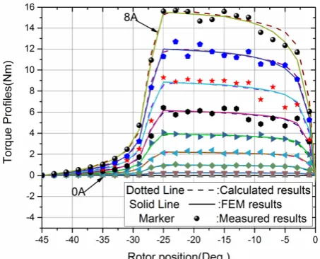
complex control strategy to reduce. As shown in Figure 3 (a) and (b), the linear interpolation resulted
123
in a surface fitting and this linear interpolation approach can be used for other non-test states to
124
obtain the necessary data for the flux linkage and the torque for any given value (i, θ).
126
(a) (b)
127
Figure 3. linear interpolation results: (a) 3-D relationships of Ψ-i-θ; (b) 3-D relationships of T-i-θ.
128
3. Theoretical Background of the SRM
129
3.1 Torque Generation
130
The principle of the torque generation in an SRM is based on the reluctance minimization of the
131
magnetic flux linkage paths. each phase torque strongly varies with the phase current and rotor
132
position variation. Generally, the phase torque Tk can be calculated from the co-energy as follows:
133
0 ( , )
( , ) 1, 2, ,
k
i
k k
k
k ik i di k m
T θ ψ θ
θ
∂
= =
∂ (1)
134
where k is the identifier of the phases, θ is the rotor position, ik is the phase current, and Ψk is the
135
phase flux linkage. All of the position angles refer to mechanical angles (except where noted). The
136
two basic equations that describe each phase flux linkage and the machine model of the SRM are as
137
follows
138
( , )
k k( , )
k kk
i
θ
L
i
θ
i
ψ
=
⋅
(2)139
k
k k
d
u
R i
dt
ψ
=
⋅
+
(3)
140
where Lk is the kth phase inductance, uk is the kth phase instantaneous voltage, and R is the phase
141
winding resistance. Because of the highly nonlinear and saturation effects of the electromagnetic
142
characterization in the SRM, the inductance Lk in Eq. (2) varies not only with phase current value but
143
also with rotor position variation.
144
By neglecting the saturated nature, we simplify the formula and assume that the inductance Lk
145
varies only with the rotor position θ. According to Eqs. (1) and (2), the torque Tk can be expressed as
146
2 ( ) 2
( , ) 0.5 k 0.5 ( )
k ik ik dL Lkp ik
T
d
θ
θ
θ
θ
= ⋅ = ⋅
(4)
147
where Lkp is denoted as the derivative of Lk. In this case, assuming that Lkp is known, Eq. (4) enables a
148
fast and simple torque calculation.
149
3.2 TSFs
150
To minimize the torque ripple, the commonly used TSFs can be classified as linear, sinusoidal,
151
exponential, and cubic and their details have been reported in [19] and [24]. Through the torque
152
control with a TSF in the region where it shares the torque with one or more phases (called the
153
commutation or overlap region), the total torque reference Tref is divided into separate torque
154
reference Tref(k) for each phase. According to the characteristics of the torque-current-position, the Tref(k)
155
is converted into the phase current reference ik with respect to the rotor position information.
157
Figure 4. Illustration of a TSF.
158
Figure 4 shows an illustration of a TSF. The kth phase torque reference denoted as Tref(k) is
159
calculated as
160
( )
0 ( ) ( )
( ) 0
u on
ref rise on on ov
ref on ov off ov
ref k
ref fall off ov off
off al
f T
T T
f T
θ
θ θ
θ θ θ θ θ
θ
θ θ θ θ θ
θ θ θ θ θ
θ
θ θ
≤ ≤
⋅ < < +
+ ≤ ≤ −
=
⋅ − < <
≤ ≤
(5)
161
where θu, θon, θov, θoff and θal are the unaligned, turn-on, overlap, turn-off and aligned angles,
162
respectively; frise(θ) and represents the ascending area and ffall(θ) represents the descending area in the
163
TSF. In the commutation region, frise(θ) must increase from 0 to 1 and ffall(θ) must decrease from 1 to
164
0. For any TSF, the function ffall(θ) that is relevant to frise(θ) can be computed as follow
165
( ) 1
(
on ov off)
fall rise
f
θ
= −
f
θ θ
+
+
θ
−
θ
(6)
166
The angle θp=2π/Nr denotes the rotor pole pitch, where Nr is the number of rotor poles. And
167
θd=2π/(mNr) denotes the angular displacement between the neighboring phases. In the case of a
168
normal SRM commutation, these angles have the following relationships:
169
2
al u p
θ
−
θ
=
θ
(7)170
2
ov off on d p d
θ
=
θ
−
θ
−
θ
≤
θ
−
θ
(8)171
Thus, we can get θp=90°,θd=30°, and θov ≤15° from Eq. (7) and (8) in the three-phase 6/4 SRM. For
172
the four-phase 8/6 SRM, we have θp=60°,θd=15°, and θov≤15°.
173
4. Evaluation Criteria
174
4.1 The MAV-RCFL
175
Materials and Methods should be described with sufficient details to allow others to replicate
176
and build on published results. Please note that publication of your manuscript implicates that you
177
must make all materials, data, computer code, and protocols associated with the publication available
178
to readers. Please disclose at the submission stage any restrictions on the availability of materials or
179
information. New methods and protocols should be described in detail while well-established
180
methods can be briefly described and appropriately cited.
181
The MAV-RCFL is easily obtained from Eq. (3). At a steady state of non-zero angular speed and
182
neglecting the phase resistance, Eq. (3) can be represented as follows, where Vdc is the phase DC-link
183
voltage:
184
dc k
d V
d
ψ
θ = ω (9)
185
It is evident that the MAV-RCFL depends on the phase DC-link voltage Vdc and the rotor angular
186
speed ω with respect to the position θ. That means that, for a given Vdc, the flux linkage derivatives
187
dΨk/dθ can estimate the rotor speed range at which the torque-speed performance theoretically allows
188
a torque-ripple-free operation. It can be seen from Eq. (9) that the maximum absolute value of dΨk/dθ
189
limits the maximum speed range ωmax. The MAV-RCFL denoted as MR is defined as
{
}
max
on off
R
d
kd
M
θ ≤ ≤θ θ
Ψ
θ
=
(10)
191
According to Eqs. (9) and (10), the maximum speed range ωmax for operating torque ripple
192
performance freely must satisfy
193
dc max
R
V M
ω ≤
(11)
194
To be specific, the smaller the maximum MR, the larger the maximum rotor speed ωmaxis. In other
195
words, the MAV-RCFL is expected to be as small as possible.
196
4.2 Copper Loss
197
Total losses in an SRM include iron loss and copper loss and the latter represent the major
198
component of the losses. Thus, the copper loss directly influences the torque-speed performance and
199
the drive efficiency. And the copper loss is in direct proportion to the square value of the rms phase
200
current Irms, which is calculated from:
201
2 2 2
2
1
1 1
( ) on ( ) ( )
off ov ov
on ov on
rms k k k
p p
d d
i i i
I θθ θθ
θ θ
θθ θθ
θ
θ
θ
θ
+ −
+ −
= + + (12)
202
Since in the region θon+θov≤θ≤θoff -θov, the kth phase produces the total torque independently as
203
shown in Figure 4 and minimizing the rms phase current Irms can be realized by decreasing the second
204
part of Eq. (12).
205
Hence, by modifying Eq. (12), an optimization objective function can be expressed as follow:
206
1
( )
1( )
min:
J i
=
qkθ
+
i
qk−θ
(13)207
where q is a bound variable satisfied q≥2. In Eq. (13), the qth-power of the current is a substitute for
208
the integration of the averaged square value of the current during the commutation.
209
A torque reference profile can now be generated for a specific TSF. The current profile and the
210
flux linkage profile are obtained using the given torque and flux-linkage characteristics. Hence, the
211
MAV-RCFL and the square value of the rms current can be computed. As discussed above, by
212
optimizing the TSFs, a wide rotor speed range and less copper loss can be obtained by minimizing
213
the MAV-RCFL and the square value of the rms current. This is the basic principle and direction for
214
selecting an optimal TSF.
215
5. Proposed TSFs
216
5.1 Optimization Objective for Proposed TSF
217
An optimization objective function that combines MAV-RCFL MR and the qth-power of current
218
J1 with a weighting factor is proposed as
219
1
min :
J
=
w
fJ
+ −
(
1
w
f)
M
R (14)220
where wf is the weighting factor satisfied 0≤wf≤1. ⎯J1 and⎯MR are the normalized values of J1 and MR
221
respectively and they can be computed from⎯J1= J1/ J1,max and ⎯MR= MR/ MR,max, where J1,max and MR,max
222
are the maxima of J1 and MR respectively.
223
When wf =1, the proposed optimization objective function only consists of the square value of
224
the rms current. In this case, the minimum copper loss is the only optimization objective. When wf =0,
225
the maximum speed range is the only optimization objective. When 0< wf <1, both maximum speed
226
range and minimum copper loss at different proportion are considered as the optimization objectives
227
in order to obtain the correct balance.
228
5.2 A Family of TSFs
229
According to the definition of a TSF from Eqs. (5) and (6), the phase torques produced by the
230
currents ik(θ) and ik-1(θ) in Eq. (13) share the total torque reference in the commutation region, which
231
are denoted as Tref(k) (θ) and Tref(k-1) (θ)= Tref - Tref(k) (θ). Thus, by neglecting the saturated effects, Eq. (13)
232
can be rewritten from Eq. (4) as
/2 /2
( ) ( )
1
1
( )
( )
0.5
0.5
q q
ref k ref ref k
kp k p
T
T
T
J
L
θ
L
−θ
−
=
+
(15)234
When dJ1/dTref(k)=0 to obtain the extreme value of J1, the desirable TSF calculated from Eq. (15) is
235
depicted as
236
( )
1
1
1
( )/
( )
ref k ref r
k p kp
T
T
L
−θ
L
θ
=
⋅
+
(16)
237
where r=q/(q-2) is an undetermined constant satisfied r≥1. Tref ·frise(θ) in Eq. (5) is defined by the right
238
part of Eq. (16) and the other section of TSF can be easily obtained from Eq. (6).
239
5.3 Comparison of the Conventional and Proposed TSFs
240
Figure 5 shows the typical profiles of four common conventional TSFs. The on angle,
turn-241
off angle, and overlap angle, θon, θoff, and θov are set to 5°, 40° and 5°, respectively. And the torque
242
reference Tref is set to 1 Nm. In Figure 5(a)-(d), the profiles (top to bottom) are the torque reference,
243
the current reference, the flux linkage reference, and the absolute value of RCFL respectively. From
244
Figure 5 (d), the values of MR for the linear, sinusoidal, exponential, and cubic TSFs are 11.78, 6.75,
245
5.05, and 19.10 Wb/rad, respectively. According to Eq. (11), the values of maximum rotor speed ωmax
246
for a torque-ripple-free operation of four common conventional TSFs are 22.9, 40, 53.5, and 14.1 rad/s,
247
which are equal to only 219, 382, 511, and 135 rpm, respectively
248
.
249
250
Figure 5. Typical profiles of four conventional TSFs.
251
252
(a) (b)
253
254
(c)
255
Figure 6. Comparison of four conventional TSFs: (a) absolute value of the RCFL; (b) peak phase current; (c) rms
256
Figure 6(a) shows the change in the MAV-RCFL with the changing torque reference, indicating
258
that the exponential TSF resulted in the lowest RCFL value. The peak values of the reference currents
259
at each torque reference are compared in Figure 6(b) showing an increase in the currents as the torque
260
reference increases. The peak current is the same for the linear TSF and the cubic TSF and it is lower
261
than for the other two TSFs. This indicates that the power converter has much smaller pressure and
262
better insulation for the linear and cubic TSFs. The rms currents at each torque reference are
263
compared in Figure 6(c), which indicates that the linear and the sinusoidal TSFs have almost the same
264
value of rms current at the torque reference between 0.5Nm and 3Nm. The rms current is lower for
265
cubic TSF than for the other TSFs.
266
In summary, if the minimum MR (when wf =0 in Eq. (14)) is the only optimization target, the best
267
choice of TSF is the exponential TSF, the second best choice is the sinusoidal TSF, and the worst choice
268
is the cubic TSF. On the other hand, if the minimum copper loss J1 (when wf =1 in Eq. (14)) is the only
269
optimization objective, the cubic TSF represents a good choice, and it also has the lowest value for
270
the peak current.
271
Figure 7 (a-d) show the typical profiles of several proposed TSFs for different r values. From
272
Figure 7, when r tends to ∞, the minimization of the copper loss is achieved theoretically because the
273
torque reference tends to be zero during the commutation region. By decreasing r, the torque
274
reference increases during the commutation region, which results in an increase in the rms phase
275
current. When r tends to 1, Figure 7(b) shows that the phase current reference of two adjacent excited
276
phases in the commutation region is equal. And it is clear that the peak value of phase current is also
277
the smallest when the TSF is defined by r→1.
278
279
Figure 7. Typical profiles of the proposed TSF family.
280
281
(a) (b) (c)
282
Figure 8. Comparison of the proposed TSFs: (a) absolute value of the RCFL; (b) peak phase currents; (c) rms
283
phase currents.
284
Figure 8(a) shows the relationship between the MAV-RCFL and the exponent r. As MR reaches
285
its minimum at r≈4, it is reasonable to choose r=4 as the exponent of the optimal TSF in Eq. 16. When
286
Tref is set to 1 Nm and Vdc is set to 270V in the case of r=4, the maximum speed range ωmax for operating
287
torque ripple performance freely can be achieved at 30 rad/s, which is equal to 286.6 rpm. The
equivalent level of the linear and the cubic TSFs are also marked with the dash-dotted line in the
289
Figure 8 (a-c) for comparison. Figure 8(b) shows the peak phase current reference as a function of the
290
exponent r. If r is larger than 3.5, the peak phase current exceeds the theoretical minimum value of
291
6.65 A by more than 5%. In Figure 6(b), the minimum peak current values of the four common
292
conventional TSFs are about three times higher than the values of the proposed TSFs. The rms phase
293
current reaches a theoretical minimum value of 3.5 A when r≥3 from Figure 8(c). Assuming a torque
294
reference of 1 Nm, the rms current values are larger for the four common conventional TSFs than for
295
the proposed TSFs at any value of r (Figure 6(c)).
296
Therefore, the TSF with the minimum MR value at r=4, denoted as TSF1 (r=4), should be used as
297
the optimal value at higher speed because it provides smaller peak phase current and lower copper
298
loss relatively.
299
6. Nonlinear Mathematical Model of Torque Profile
300
The optimal TSF is obtained by solving the optimization problem in Eq. (14). However, Eq. (4)
301
is utilized to approximate the phase torque based on a linear relationship between the phase flux
302
linkage and the current as shown in Eq. (3). An analytic invertible torque function that represents the
303
nonlinear and saturation effects appropriately was used as follows [26]:
304
2 1/
( ) 1
( , )
2 (1 ( ) ) kp
k n n
i L i
T
f i
θ
θ
θ
=
+ (17)
305
where Lkp(θ), f(θ) and n are the undetermined parameters that are dependent on the rotor position
306
and the motor parameters.
307
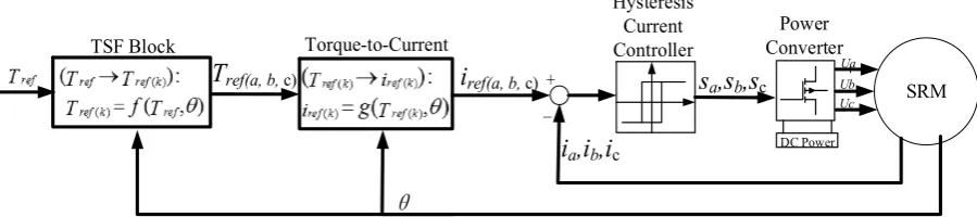
308
Figure 9. Comparison of the calculated, FEA, and measured static torque characteristics for 0 to 8 A with an
309
increment of 1 A.
310
As shown in Figure 9, by choosing reasonable parametersfor Lkp(θ) and f(θ), the characteristics
311
of the torque-current-position obtained from Eq. (17) agree well with those using FEA or those from
312
experimental measurements. After rejecting the improbable solution, the current reference can be
313
rewritten as Eq. (18) by inverting the torque equation in Eq. (17) as follows:
314
1/ 2
0 ( )
( ) ( )
2 ( , )
2 4
( ) 2
n n p k
k k
k kp
f f L
T i T
T L
θ
θ θ
θ
θ
= + +
(18)
315
The data of the two angular functions Lkp(θ) and f(θ) stored in the digital controller can be used
316
to calculate the current reference according to Eq. (18), instead of using the 3-D lookup table of T-i-θ.
317
7. Simulation Results and Comparison
318
Figure 10 shows the block diagram of the torque control using the TSF method for the studied
319
SRM. The individual phase torque reference is defined from the total torque reference by the TSF
block. In the “Torque-to-Current” block, the phase torque references are converted into phase current
321
references the rewritten torque-current profile model of the SRM (Eq. (18)). A hysteresis current
322
controller is used for the phase current tracking its reference waveforms.
323
Matlab /Simulink was used to for the simulation model of the three-phase 6/4 SRM with 7.5 kW,
324
3000 rpm, and 270 V DC-link voltage by using the static torque characteristic profiles shown in Figure
325
9 and obtained using Eq. (17). For the phase current tracking its reference waveforms accurately, it is
326
appropriate to set the hysteresis band of the current controller to ±0.1 A through simulation test. The
327
phase current reference is calculated using Eq. (18). The same sampling time tsample=1μs is set in all
328
simulation. Finally, the evaluation indices in terms of peak phase current, rms phase current, and
329
torque ripple factor are compared between the proposed and the classical TSFs.
330
The torque ripple factor is defined as follows:
331
% max min 100%
ave
T T
T.R
T
−
= ×
(19)
332
where Tmax, Tmin, and Tave are the maximum, minimum, and average torque, respectively.
333
+ SRM
i
ref(a, b, c)i
a,i
b,i
c
-Hysteresis Current Controller
Power Converter
s
a,s
b,s
cUa Ub Uc
θ
DC Power
T
ref(a, b, c)TSF Block Torque-to-Current
334
Figure 10. Block diagram of the torque control using the TSF method.
335
7.1 Simulation Results
336
The CCC (current chopping control) method is common in the SRM control and was investigated
337
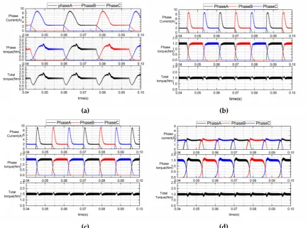
in [27]. The simulation results for the proposed TSF1 (r=4) are compared with the CCC and the
338
conventional TSFs at a torque reference Tref=1.5 Nm and a rotor speed of 1000 rpm (Figure11 (a)-(d)).
339
Since the rotor speed 1000 rpm of all TSFs is higher than the maximum rotor speed ωmax, the phase
340
current cannot track its reference. The torque ripple factors T.R% for the CCC, the linear, sinusoidal,
341
and the proposed TSFs are 116.7%, 28.7%, 22.0%, 23.5%, respectively. The rms currents are 3.5 A for
342
the linear and sinusoidal TSFs, and 3 A for the TSF1 (r=4).
343
The simulation results for the CCC, the linear, the sinusoidal, and the proposed TSFs at a torque
344
reference of Tref=1.5 Nm and a speed of 3000 rpm are shown in Figure 12 (a)-(d). As the rotor speeds
345
up, the phase current deviates from its reference significantly during the current rising region. And
346
the phase current exhibits a tail phenomenon at the same time during the current declining region.
347
Therefore, the output torque cannot track its reference accurately and the torque ripple increases
348
obviously. The torque ripple factors T.R% are 182.3%, 61.3%, 60.8%, and 36.6%, respectively. For the
349
CCC, the linear, the sinusoidal, and the proposed TSF1 (r=4), the peak phase currents are 8.8 A, 9.4
350
A, 9.5 A, and 5.5 A, and the rms phase currents are about 5.4A, 5.4A, 5.3A and 3.8A, respectively. It
351
is evident that the CCC method results in a comparatively smaller peak phase current compared with
352
the conventional TSFs. However, the torque ripple is not acceptable because it is three times higher
353
than that of the proposed TSF1 (r=4). The linear and sinusoidal TSFs almost have the same
354
performance with regard to the torque ripple and the peak phase current, which is approximately
355
twice as high as those for the proposed TSF1 (r=4). The proposed TSF1 (r=4) results in the lowest
356
torque ripple, which is 1/2 of the torque ripple of the linear TSF. In addition, the required phase
357
current is lower than for the CCC. The control performance is clearly improved by using the proposed
358
TSF1 (r=4).
360
(a) (b)
361
362
(c) (d)
363
Figure 11. Simulation results (Tref=1.5 Nm, 1000 rpm): (a) CCC; (b) Linear TSF; (c) Sinusoidal TSF; (d) TSF1 (r=4).
364
365
(a) (b)
366
367
(c) (d)
368
Figure 12. Simulation results (Tref=1.5 Nm, 3000 rpm): (a) CCC; (b) Linear TSF; (c) Sinusoidal TSF; (d) TSF1 (r=4).
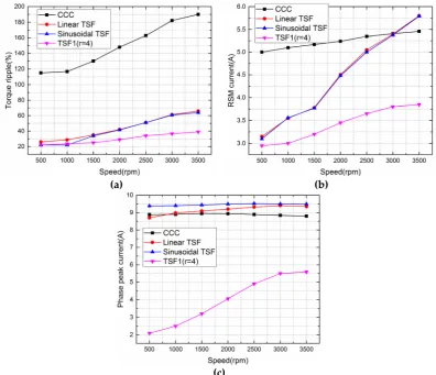
7.2 Comparison of the Simulation Results
370
Figure 13(a) shows the comparison results of the torque ripple between the CCC, the linear, the
371
sinusoidal, and the proposed TSF1 (r=4) when the torque reference is set to 1.5 Nm. The CCC is the
372
worst choice in all methods. For the conventional TSFs, the torque ripples are almost two to three
373
times higher at 3000 rpm than at 1000 rpm. And at 3000rpm, the torque ripple of the proposed TSF1
374
(r=4) is nearly one half of the other TSF methods. That means the proposed TSF1 (r=4) have a better
375
performance than the other control method. Actually at a lower rotor speed, the torque ripple of the
376
proposed TSF is obviously affected by the hysteresis band of the current controller. Therefore, the
377
torque ripple can be decreased further more by reducing the inherent current ripple of the hysteresis
378
controller.
379
Figure 13 (b) shows the comparison results of the rms current for all control methods and the
380
CCC is also the worst choice. At the rotor speed less than 500rpm, the proposed and the conventional
381
TSFs exhibits almost a similar rms current. As the rotor speeds up, due to the poorer current tracking
382
performance, the rms currents of the linear and sinusoidal TSFs increase significantly. However, the
383
rms current for the proposed TSF remains relatively as the speed increases.
384
The peak current is much smaller for the TSF1 (r=4) than those for the other methods, which
385
have smaller hardware pressure (Figure 13(c)). At a higher speed, the peak currents of the
386
conventional TSFs decrease significantly due to the poorer current tracking performance by the
387
inductance effect. Therefore, the TSF1 (r=4) is a better choice for reducing torque ripple and lower
388
copper loss relatively.
389
390
(a) (b)
391
392
(c)
393
Figure 13. Comparison of CCC and different TSFs: (a) torque ripple; (b) rms phase current; (c) peak current.
394
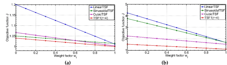
Figure 14(a) and (b) show the values of the objective function J for different weight factors wf at
395
speeds of 1000 rpm and 3000 rpm. It is evident that the linear TSF is the worst choice because its J
396
values are always much larger than those of the other TSFs at any weighting factor. The sinusoidal
397
and cubic TSFs have almost the same J values at a speed of 1000 rpm. However, as the speed increases,
the cubic TSF exhibits a better performance. At any weight factor wf or any speed, the proposed TSF1
399
(r=4) has the best minimum J values when compared to the sinusoidal or cubic TSFs.
400
401
(a) (b)
402
Figure 14. The values of the objective function J at different weight factors wf : (a) 1000 rpm, (b) 3000 rpm.
403
8. Experimental Results
404
The proposed TSF is validated with an experiment using a three-phase 6/4 SRM with 7.5 kW,
405
3000 rpm, and 270 V DC-link voltage (shown in Figure 15). A Texas Instruments (TI) TMS320F2812
406
digital signal processor (DSP) is used as a digital controller. The T-i-θ characteristics are stored as
407
look-up tables in the DSP. The SRM is driven by a three-phase asymmetric inverter and the motor
408
shaft is coupled with a torque-speed sensor and position sensor. There is one current sensor on each
409
phase line. A synchronous generator with a resistance box is used as the load.
410
411
AC DC J1+ J1-L N 220VAC 50Hz J3 J4 Optoisolation circuit 3-Phase power converter J8 Flat ribbon cablePh as eA 1 Ph as eA 2 Ph as eB 1 Ph as eB 2 Ph as eC 2 Ph as eC 1 Current sensor J2-1 J2-2 J2-3 J2-4 J2-5 J2-6
Red Blue Blac
k Resistance load box Torque-speed sensor J5 J6 Cable SRM SG + -DC + Filter circuit +-ω T iA iB iC M ic roc ont ro lle r J10 J7 TMS320F2812 PWM I/O JTAG RS-232 Computer Position-sentor J9 θ
412
Figure 15. Experimental setup of the SRM drive system
413
Figure 16 shows the measured phase current and instantaneous torque at 3000 rpm at a torque
414
reference of Tref=1.5 Nm. For the CCC, the linear TSF, the sinusoidal TSF and the proposed TSF1 (r=4),
415
the torque ripples are around 184%, 67.8%, 66.7%, and 40.4%, respectively compared to the values of
416
182.3%, 61.3%, 60.8%, and 36.6% in simulation results shown in Figure 12. And the peak phase
417
currents are 8.9 A, 9.5 A, 9.5 A, and 5.9 A, and the rms phase currents are about 5.6A, 5.4A, 5.4A and
418
3.9A, respectively. This indicates that the experimental results agree well with the results of the
419
simulation in terms of current waveforms, torque ripple and torque response under the same
420
operating conditions. Due to a current tracking error, the CCC and the conventional TSFs show much
421
higher torque ripples compared to the TSF1 (r=4), which achieves better tracking and has a nearly flat
422
output torque, ignoring the torque ripple caused by the inherent current ripple of the hysteresis
425
Figure 16. Experimental results (speed=3000 rpm, Tref=1.5 Nm): (a) CCC; (b) Linear TSF; (c) Sinusoidal TSF; (d)
426
TSF1 (r=4).
427
Assuming the total electromagnetic torque T is periodic when the actuation current is constant
428
or position-periodic, the total torque T can be extended using a Fourier series as follows:
429
0 0
1
( )
cos
k k
k
T t
∞t
kN
ω
ϕ
=
+
+=
(19)
430
where N=3 for the three phases of the 6/4 SRM. Figure 17 (a)-(d) depicts the Fourier analysis of the
431
experimental results of the total torque shown in Figure 16; the units for the phase and amplitude on
432
the y-axis are rad and Nm, respectively. It is evident that the harmonic component of the proposed
433
TSF1 (r=4) is the least. Thus, the results of the simulation and experimental prove that the
torque-434
speed performance and the drive efficiency are significantly improved by using the proposed TSF.
435
436
(a) (b)
437
438
(c) (d)
439
Figure 17. Harmonic component and phase of the total torque (Tref=1.5Nm, speed=3000 rpm): (a) CCC; (b) Linear
440
TSF; (c) Sinusoidal TSF; (d) TSF1 (r=4).
441
9. Conclusion
443
In this paper, based on the modified optimal criteria with the torque-speed performance and the
444
drive efficiency, a computational procedure for the optimization model of a TSF has been described,
445
including the maximization of the torque-speed range and the minimization of copper loss. In
446
addition, by modifying the optimization objective of the qth-power current, a TSFs family with regard
447
to torque capability is presented and the proposed TSF1 (r=4) is compared with the conventional
448
TSFs. The torque reference can be directly converted into the current reference using the rewritten
449
torque-current profile model of the SRM either in the linear or the saturation magnetic region. The
450
evaluation indices and the performance of the proposed and the classical methods are compared in
451
terms of peak phase current, rms phase current, and torque ripple factor. The experimental results,
452
which match the simulation results very well, show that no matter the rotor speed is low or high, the
453
proposed TSF1 (r=4) has the lowest peak and rms phase current compared with the CCC, the linear,
454
and the sinusoidal TSF. And the proposed TSF1 (r=4) has a commutation torque ripple ratio that is
455
one-third less compared to the conventional TSFs in the saturation magnetic region at a speed of 3000
456
rpm. Moreover, the proposed TSF1 (r=4) improves the drive efficiency, increases the rotor speed
457
range of the torque-ripple-free operation, and reduces the requirements of the peak and rms phase
458
current. The validity and superiority of the proposed control method are experimentally proved.
459
Author Contributions: Wei Ye and Qishuang Ma conceived and designed the experiments; Wei Ye performed
460
the experiments under the help of Poming Zhang; Wei Ye and Qishuang Ma analyzed the data; Poming Zhang
461
contributed analysis tools; Wei Ye wrote the paper.
462
Conflicts of Interest: The authors declare no conflict of interest. The founding sponsors had no role in the design
463
of the study; in the collection, analyses, or interpretation of data; in the writing of the manuscript, and in the
464
decision to publish the results.
465
Appendix A
466
Table A1. Parameters of the studied SRM prototype
467
Stator
6 poles (poles arc:26°) Inner diameter: 95 mm Outer diameter:150 mm
Yoke high:12.2 mm
Rotor
4 poles (poles arc:27°) Shaft diameter:40 mm Yoke high:14.5 mm
Stack length 40 mm
Turns 150 turns/phase
Air gap 0.3 mm
Winding resistor: 0.65 Ω/phase
Type of silicon steel D25_50
References
468
1. Krishnan R. Whither motor drives: a case study in switched reluctance motor drives. International Conference
469
on Electrical Machines and Systems(ICEMS2007), Seoul, South Korea, Oct. 2007, pp. 472-480; Publisher: IEEE.
470
2. Hannoun H.; Hilairet M.; Marchand C. High performance current control of a switched reluctance machine
471
based on a gain-scheduling PI controller. Control Engineering Practice, 2011, vol. 19, pp.1377-1386, DOI:
472
10.1016/j.conengprac.2011.07.011.
473
3. Bose B.K. Neural network applications in power electronics and motor drives an introduction and
474
perspective. IEEE Trans. Ind. Electron., 2007, vol.54, no.1, pp.14–33, DOI: 10.1109/TIE.2006.888683.
475
4. Anwar M.N.; Husain I.; Radun A.V. A comprehensive design methodology for switched reluctance
476
5. Kalaivani L.; Subburaj P.; Iruthayarajan M.W. Speed control of switched reluctance motor with torque
478
ripple reduction using non-dominated sorting genetic algorithm (NSGA-II). International Journal of Electrical
479
Power and Energy Systems, 2013, vol.53, pp.69-77, DOI: 10.1016/j.ijepes.2013.04.005.
480
6. Choi Y.K.; Yoon H.S.; Koh C.S. Pole-shaped optimization of a switched reluctance motor for torque ripple
481
reduction. IEEE Trans. on Magn., 2007, vol. 43, no. 4, pp. 1797-1800, DOI: 10.1109/TMAG.2006.892292.
482
7. Husain I. Minimization of torque ripple in SRM drives. IEEE Trans. Ind. Electron., 2002, vol. 49, no. 1, pp.
483
28-39, DOI: 10.1109/41.982245.
484
8. Daryabeigi E.; Dehkordi B.M. Smart bacterial foraging algorithm based controller for speed control of
485
switched reluctance motor drives. International Journal of Electrical Power and Energy Systems, 2014, vol.62,
486
pp.364-373, DOI: 10.1016/j.ijepes.2014.04.055.
487
9. Sahoo S.K.; Panda S.K.; Xu J. Indirect torque control of switched reluctance motors using iterative learning
488
control. IEEE Trans. Ind. Electron., 2005, vol.56, no.8, pp.200-208, DOI: 10.1109/TPEL.2004.839807.
489
10. Sahoo S.K.; Panda S.K.; Xu J. Iterative learning-based high-performance current controller for switched
490
reluctance motors. IEEE Trans. Energy Convers., 2004, vol.19, no.3, pp. 491-498, DOI:
491
10.1109/TEC.2004.832048.
492
11. Fuengwarodsakul N.H.; Menne M.; Inderka R.B.; De Doncker R.W. High-dynamic four-quadrant switched
493
reluctance drive based on DITC. IEEE Trans. Ind. Appl., 2005, vol.41, no.5, pp. 1232-1242, DOI:
494
10.1109/TIA.2005.853381.
495
12. Inderka R.B.; De Doncker R.W. DITC-Direct instantaneous torque control of switched reluctance drives.
496
IEEE Trans. Ind. Appl., 2003, vol.39, no.4, pp. 1046-1051, DOI: 10.1109/TIA.2003.814578.
497
13. Hannoun H.; Hilairet M.; Marchand C. Design of an SRM speed control strategy for a wide range of
498
operating speeds. IEEE Trans. Ind. Electron., 2010, vol.57, no.9, pp.2911-2921, DOI:
499
10.1109/TIE.2009.2038396.
500
14. Mademils C.; Kioskeridis I. Performance optimization in switched reluctance motor drives with online
501
commutation angle control. IEEE Trans. Energy Convers., 2003, vol.18, no.3, pp.448-457, DOI:
502
10.1109/TEC.2003.815854.
503
15. Husain I.; Hossain S.A. Modeling, simulation, and control of switched reluctance motor drives. IEEE Trans.
504
Ind. Electron., 2005, vol.52, no.6, pp. 1625-1634, DOI: 10.1109/TIE.2005.858710.
505
16. Sahoo S.K.; Dasgupta S.; Panda S.K.; Xu J. A Lyapunov function based robust direct torque controller for a
506
switched reluctance motor drive system. IEEE Trans. Power Electron., 2012, vol.27, no.2, pp.555-564, DOI:
507
10.1109/TPEL.2011.2132740.
508
17. Mikail R.; Husain I.; Sozer Y.; Islam M.; Sebastain T. Torque-ripple minimization of switched reluctance
509
machines through current profiling. IEEE Trans. Ind. Appl., 2013, vol.49, no.3, pp.1258-1267, DOI:
510
10.1109/TIA.2013.2252592.
511
18. Shaked N.T.; Rabinovici R. New procedures for minimizing the torque ripple in switched reluctance motors
512
by optimizing the phase-current profile. IEEE Trans. Magn., 2005, vol.41, no.3, pp. 1184-1192, DOI:
513
10.1109/TMAG.2004.843311.
514
19. Xue X.D.; Cheng K.W.E.; Ho S.L. Optimization and evaluation of torque sharing function for torque ripple
515
minimization in switched reluctance motor drives. IEEE Trans. Power Electron., 2009, vol.24, no.9,
pp.2076-516
2090, DOI: 10.1109/TPEL.2009.2019581.
517
20. Pop A.C.; Petrus V.; Martis C.S.; and et al. Comparative study of different torque sharing functions for
518
losses minization in switched reluctance motors used in electric vehicles propulsion. Proceedings of 13th
519
International Conference on Optimization of Electrical and Electronic Equipment (OPTIM), Brasov, Romania,
520
May 2012, pp. 356-365; Publisher: IEEE.
521
21. Ye J.; Bilgin B.; Emadi A. An offline torque sharing function for torque ripple reduction in switched
522
reluctance motor drives. IEEE Trans. Energy Convers., 2015, vol.30, no.2, pp.726-735. DOI:
523
10.1109/TEC.2014.2383991.
524
22. Ye J.; Bilgin B.; Emadi A. An extended-speed low-ripple torque control of switched reluctance motor drives.
525
IEEE Trans. Power Electron., 2015, vol.30, no.3, pp.1457-1470, DOI: 10.1109/TPEL.2014.2316272.
526
23. Lee D.H.; Lee Z.G.; Ahn J.W. A simple nonlinear logical torque sharing function for low-torque ripple SR
527
drive. IEEE Trans. Ind. Electron., 2009, vol.56, no.8, pp. 3021-3028, DOI: 10.1109/TIE.2009.2024661.
528
24. Dowlatshahi M.; Nejad S.M.S.; Moallem M.; Ahn J.W. Torque ripple reduction of switched reluctance
529
motors considering copper loss minimization. 2014 IEEE International Conference on Industrial Technology
530
25. Dowlatshahi M.; Nejad S.M.S.; Ahn J.W.; Moallem M. Copper loss and torque ripple minimization in
532
switched reluctance motors considering nonlinear and magnetic saturation effects. Journal of Power
533
Electronics, 2014, vol.14, no.2, pp.351-361, DOI: 10.6113/JPE.2014.14.2.351.
534
26. Vujičić V.P. Modeling of a switched reluctance machine based on the invertible torque function. IEEE Trans.
535
Magn., 2008, vol.44, no.9, pp. 2186- 2194, DOI: 10.1109/TMAG.2008.2000663.
536
27. Xue X.D.; Cheng K.W.E.; Ho S.L. Study of power factor in SRM drives under current hysteresis chopping
537
control. Fourtieth IAS Annual Meeting, Conference Record of the 2005 Industry Applications Conference,