ISSN(Online): 2320-9801
ISSN (Print): 2320-9798
International Journal of Innovative Research in Computer
and Communication Engineering
(An ISO 3297: 2007 Certified Organization)
Vol. 3, Issue 3, March 2015
Performance Analysis of PAPR Reduction
Using DFT-Spreading OFDMA Technique
Alcardo Alex Barakabitze, Tan Xiaoheng
School of Communication Engineering, Chongqing University, China
ABSTRACT: The 3GPP long term evolution (3GPP-LTE) has adopted the Discrete Fourier Transform Spreading Orthogonal Frequency Division Multiple Access (DFTS-OFDMA) technique to be used in the uplink air interface for the next generation cellular systems. The DFTS-OFDMA is also a candidate of radio interface technologies for the IMT-Advanced standards in ITU-R. This technique has been adopted for uplink transmission due to its attractive feature of lower PAPR archived by precoding data symbols using a DFT operation at the transmitter.
In this paper, we analyse the performance of DFT-Spreading OFDMA technique in PAPR reduction by using the IFDMA and LFDMA subcarriers mapping modes. We also analyse the performance of the DFTS OFDMA technique for PAPR reduction as the number of subcarriers allocated to each user varies, specifically with the LFDMA subcarriers mapping mode. Simulation results show that, the IFDMA improves PAPR performance significantly than LFDMA with pulse shaping and wihout pulse shaping but at a cost of increased bandwidth.Moreover, the performance of DFT-Spreading with LFDMA improves when the number of subcarriers allocated to users becomes small. Although, in-terms of PAPR power efficiency, the IFDMA performs better than LFDMA allocation scheme, but LFDMA is very superior in terms of throughput when channel dependent scheduling is utilized and has been widely implemented in LTE.
KEYWORDS: OFDMA, Peak to Average Power Ratio (PAPR), Subcarriers, FDMA, Orthogonal
1. INTRODUCTION
ISSN(Online): 2320-9801
ISSN (Print): 2320-9798
International Journal of Innovative Research in Computer
and Communication Engineering
(An ISO 3297: 2007 Certified Organization)
Vol. 3, Issue 3, March 2015
Suppose that, M is the number of subcarriers allocated to each user, then the DFTS-OFDMA will use M-point DFT for spreading and the output of DFT is assigned to the subcarriers of IFFT. Myung et.al [3] has shown that, PAPR reduction effect is highly dependent on the way of assigning the subcarriers to each terminal as explained in the next section.
In this paper, we will examine the PAPR performance of transmit symbols for each block in the IFDMA and LDFMA with pulse shaping numerically. We analyse the PAPR reduction performance of DFTS-OFDMA technique with
IFDMA and LFDMA with different values of the roll-off factor
0
1
of the RC filter with pulse shaping after IFFT. The rest of this paper is organized as follows: section II provides the literature review of related works concerning DFTS-OFDMA system. Section III describes the DFTS-OFDMA system model and subcarriers mapping schemes. Section IV highlights the PAPR of DFT-Spreading OFDMA Signals. We provide the numerical simulation results in section V before concluding our remarks in section VI.II. RELATED WORKS
The DFTS-OFDMA is regarded to be a good solution of single carrier based uplink multi-access scheme for PAPR reduction. Wu and Haustein [16] has reported the PAPR reduction by DFT precoding technique and studied the energy and spectral efficiency in the uplink for 3GPP-LTE.They showed that, the DFT precoding with filtering similar to that of single carrier transmission with appropriate pulse shaping is a reasonable option to increase the cell edge throughput. Li et.al [17] investigated the PAPR reduction in MC/DS CDMA systems by using the DFT Spreading
codes where about
6dB
PAPR was achieved at CCDF of10
3 in the MC/DS CDMA system with 12 data carriers. Wu et.al [19] studied on the visible light communication (VLC) using LED Array with DFT-Spread OFDM. Based on their detailed comparisons of DFT-Spread OFDM in terms of PAPR reduction for VLC and RF systems, the simulation results show that DFT-Spread OFDM leads to a reduced PAPR and achieves a performance gain in BER without any loss of system transmission rate. Basak et.al [19] explored theimprovement of PAPR in the uplink by using the DFT spreading technique so as to preserve the limited battery power in a mobile terminal. They found that, SC-FDMA systems with IFDMA and LFDMA have better PAPR performances, as compared to OFDMA systems.The PAPR performance comparison between Localized and Distributed-Based SC-FDMA techniques was done in [20]. Myung[21] studied the SC-FDMA focusing on physical layer aspects, PAPR characteristics and channel-dependent resource scheduling of SCFDMA. He found that, the two different categories of subcarrier mapping methods, localized and distributed, give the system designer the flexibility of adapting to different radio environments.Soltani[21] compared the SC-FDMA and OFDMA as 3GPP Long-Term Evolution Uplink. It was concluded that, the SC-FDMA is the better option for a cellular uplink in LTE, because of its higher efficiency due to low PAPR, its lower sensitivity to frequency offset because it has at most only two adjacent users, and its capacity is about the same as OFDMA. Azurdia-Meza et.al [22] derived the pulse shaping filter which satisfy the Nyquist-I criterion and implemented the PAPR reduction over SC-FDMA scheme. The simulation results showed that PAPR was greatly reduced compared to that of the raised cosine filter, which is widely used in wireless communications. In [23], the PAPR reduction of SC-FDMA by hybrid (clipping & pulse shaping) technique is reported to enhance the power efficiency of the handset as well as improving the uplink throughput and operating range.III. DFT-SPREADING OFDMASYSTEM MODEL
ISSN(Online): 2320-9801
ISSN (Print): 2320-9798
International Journal of Innovative Research in Computer
and Communication Engineering
(An ISO 3297: 2007 Certified Organization)
Vol. 3, Issue 3, March 2015
Encoder Serial-to-Parallel conversion
N-point DFT operation
Subcarrier Mapping
N-IDFT Operation
Pulse Shaping& DAC
Decoder Parallel-to-Serial conversion N-point IDFT operation
Subcarrier
Demapping N-point DFT
operation ADC
C
h
an
n
e
l
Input signals
Output data signals
Fig.1:A block diagram of DFT-Spreading OFDMA system
A. Subcarriers mapping schemes
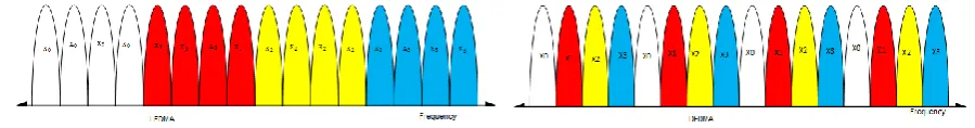
The performance of DFTS-OFDMA system is mainly affected by the type of subcarrier mapping scheme being used. Three different schemes are used in the DFT-Spreading technique to assign subcarriers among users. These schemes are: The Distributed Frequency Division Multiplexing Access (FDMA), the Localized FDMA (LFDMA) and the Interleaved FDMA (IFDMA) approach.
Localized FDMA
In the localized scheme, each user is allowed to use a set of adjacent subcarriers to transmit data. This means for localized DFTS-OFDMA, only a fraction of the total bandwidth is used by one user as shown in Fig.2. The advantage of LFDMA is that, it achieves multi user diversity in frequency selective channel if each user is assigned subcarriers that have high channel gain [11]. The drawback of this subcarrier mapping scheme is that, it eliminates the chance of getting frequency diversity in the channel. It also requires channel state information (CSI) to map the data into the best adjacent symbols [12].In the localized subcarrier mapping mode, the modulation symbols are assigned to M adjacent subcarriers [8].
Distributed FDMA
The subcarriers in a distributed mode used by a user are spread over the entire bandwidth. The information to spread is used to provide inherent frequency diversity. In the DFDMA, M DFT point outputs are distributed over the total N
subcarriers with zeros filled in (N-M) unused subcarriers (see Fig.2 and Fig.4). However, when the DFT outputs in DFDMA are distributed with an equal distance such that N/M= S, then this kind of technique is termed as the Interleaved FDMA (IFDMA) and becomes a special case of DFDMA scheme where S represents the bandwidth spreading factor[7].The drawback of this scheme is that, it loses user diversity[11]. Figure 2 shows the two approaches of allocating subcarriers in the DFDMA and IFDMA with M=4, S=4, and N=16.
Figure 2: Assignment of subcarriers to 4 users with N=12; M=4 and S=4
ISSN(Online): 2320-9801
ISSN (Print): 2320-9798
International Journal of Innovative Research in Computer
and Communication Engineering
(An ISO 3297: 2007 Certified Organization)
Vol. 3, Issue 3, March 2015
{ { { Ze ros Ze ros Ze ros X[0] X[1] X[2] X[M-1] X’[0] X’[N-1]
DF
DM
A
{
{
Ze ros Ze ros X’[0] X[0] X[1] X[M-1] LFDMAFig.3: Mapping of subcarriers for uplink in OFDMA systems using LFDMA and DFDMA
The subcarriers mapping relationship between 4-point DFT and 12-point IDFT and the examples of DFT spreading in DFDMA, LFDMA, and IFDMA with number of subcarriers N=12, number of subcarriers allocated to users(M)=4, and the spreading factor(S)=3 is shown in Fig.4 below.
x[m] X[i] X’[k]:In terleaved FDM A X’[k]:Lo calized FDM A X’[k]:Distributed FDM A
X[0] X[1] X[2] X[3]
X[0] X[1] X[2] X[3] X[0] X[1] X[2] X[3]
X[0] 0 0 X[1] 0 0 X[2] 0 0 X[3] 0 0
X[0] 0 X[1] 0 X[2] 0 X[3] 0 0 0 0 0
X[0] X[1] X[2] X[3] 0 0 0 0 0 0 0 0
Frequency
4-point DFT
Fig.4: DFT Spreading in DFDMA, LFDMA, and IFDMA
Encoder +
Interleaver Modulation S\P DF
T S pr ea di ng F D M A M appi ng IF F T P
/S Insert Guard
Interval
Encoder +
Interleaver Modulation Repetition Frequency Shift
Insert Guard Interval X[m] M X[i] X[k] N X[n] 2 1 0
[ ]
[ ]
,
4
j nk
N
N
n
DFT X k
x n e
M
ISSN(Online): 2320-9801
ISSN (Print): 2320-9798
International Journal of Innovative Research in Computer
and Communication Engineering
(An ISO 3297: 2007 Certified Organization)
Vol. 3, Issue 3, March 2015
Fig.5 shows the block diagram of IFDMA uplink transmitter with DFT-Spreading technique where the input data
[ ]
x m
is DFT-spread in order to generateX i
[ ]
.FDMA mapping is then performed to generate data symbolsX k
[ ]
before IFFT operation to obtain
x n
[ ]
and convert the signal from parallel to serial. The guard interval that is larger than the maximum channel delay is then inserted as a cyclic prefix (CP) like in standard OFDMA in order to avoid interference from preceding transmission symbols. In fact, IFDMA is equivalent to OFDMA-Code Division Multiplexing (CDM) with block interleaved frequency allocation and can be completely generated in the time domain without using the Fourier transform [9]. The time domain generation of IFDMA uses compression and repetition as described in more detail in [10].IV. PAPR OF DFT-SPREADING OFDMASIGNALS
We consider the PAPR reduction of the DFTS-OFDMA for distributed subcarrier mapping mode, the IFDMA.
Through our derivations, we let N/M= S. Suppose the data to be modulated is
x
n:
n
0,1,...,
M
1
and
x
k:
k
0,1,...,
M
1
are the frequency domain samples after operation of the DFT on
x
n:
n
0,1,...,
M
1
.Consider also the frequency domain samples after subcarrier mapping to be
X
l:
l
0,1,...,
N
1
.The time symbols after IDFT of
X
l:
l
0,1,...,
N
1
will be
x
n:
n
0,1,...,
N
1
.Therefore, the complex pass-band transmit signal of DFT-Spreading OFDMAx t
( )
for a block of data can be expressed as:1
0
( )
c(
)
N
j t
n n
x t
e
x r t
nT
(1) wherec
is the carrier frequency of the DFT-Spreading system andr t
( )
is the baseband pulse. In this paper, we investigate the effect of pulse shaping on the PAPR performance of DFT-spreading technique. In order to achieve our objectives, we employ the Raised-Cosine (RC) which is the widely used pulse shape in wireless communications [4], and defined in time domain as follows:
2 2
2
cos
( )
sin
4
1
t
t
r t
t
T
T
(2) Where
represent the roll-off-factor of the RCwhich ranges from 0 to 1.Then, the PAPR of the DFT-Spreading OFDMA transmit signal
x t
( )
with pulse shaping is defined as follows:
2
0
2
0
max | ( ) |
peak power of ( )
average power of ( )
1
| ( ) |
t NT NT
x t
x t
PAPR
x t
x t
NT
(3)Without pulse shaping we mainly refer to the use of the rectangular pulse shaping where the symbol rate sampling gives the same PAPR as the continuous case due to the fact that the DFT-Spreading OFDMA signal is modulated over a single carrier[5].Therefore, by using symbol rate sampling, the PAPR reduction without pulse shaping is expressed as follows: 2 0,1,..., 1 1 2 0
max
|
|
ISSN(Online): 2320-9801
ISSN (Print): 2320-9798
International Journal of Innovative Research in Computer
and Communication Engineering
(An ISO 3297: 2007 Certified Organization)
Vol. 3, Issue 3, March 2015
It has been shown in [17] and [44] that, the analytical time domain symbols of IFDMA is
x
m1
.
x
ms
(5), whereas theanalytical time domain symbols of LFDMA is
1 2
( ) 2 0
1
1
1
.
1
q M
j p
S
m n p q
j
p M SM
x
x
e
s
M
e
(6) for.
, 0
1
0
1
m
S n q
n
N
and
q
S
It has been also shown that from (6), the LFDMA signal in the time domain, has exact copies of input time symbols in N-multiple sample positions. In-between values are sum of all the time input symbols in the input block with different complex-weighting, which would increase the PAPR. In fact, the time-domain LFDMA signal becomes the 1/S-scaled copies of the input sequence at the multiples of S in the time domain. On the other hand, the resulting time symbols of
x
m in IFDMA subcarrier mapping mode, becomes just a repetition of the original input symbols
x
n in the timedomain as shown in Fig.5.
The next section examines the PAPR performance of transmit symbols for each block in the IFDMA and LDFMA with pulse shaping and without pulse shaping numerically. Through simulations, we analyse the PAPR reduction performance of DFT-spreading OFDMA technique with IFDMA and LFDMA with different values of the roll-off
factor
0
1
of the RC filter. We also analyse the performance of the DFT-S OFDMA technique for PAPR reduction as the number of subcarriers allocated to each user varies(i.e No. of subcarriers allocated to each user=M).V. SIMULATION RESULTS
This section presents the simulation results of the DFTS-OFDMA technique for PAPR reduction. TheCCDFs of PAPR for LFDMA and IFDMA are evaluated and compared through simulations. We analyse the PAPR reduction performance of DFT-spreading OFDMA technique with IFDMA and LFDMA with different values of the roll-off
factor
0
1
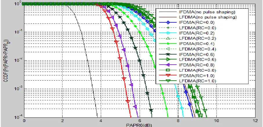
of the RC filter with pulse shaping and without pulse shaping after the IFFT operation. Simulation parameters used are as follows: 100000 OFDM blocks for iteration were used in order to generate the CCDF of the PAPR.128 subcarriers were considered where the input data block size M was 32 and the spreading factor S was 4.The8 times oversampling factor for pulse shaping with the RC
0
1
was used whereas the symbol constellation considered were QPSK and 16-QAM.Fig.6 shows the CCDF and PAPR performance of IFDMA and LFDMA spreading techniques with N=256 and QPSK symbol constellations.Simulation results shows that with no pulse shaping,both IFDMA and LFDMA performs poor because of considerable high PAPR.However,with pulse shaping,the IFDMA performs better with significant PAPR
ISSN(Online): 2320-9801
ISSN (Print): 2320-9798
International Journal of Innovative Research in Computer
and Communication Engineering
(An ISO 3297: 2007 Certified Organization)
Vol. 3, Issue 3, March 2015
Fig.6: The Performance of IFDMA and LFDMA by using pulse shaping and without pulse shaping with QPSK,N=128 and
Cosine(RC),
0.0, 0.2, 0.4, 0.6, 0.8 and 1.0
Raised
Fig.7:The Performance of IFDMA and LFDMA by using pulse shaping and without pulse shaping with 16-QAM,N=128, and
Cosine(RC),
0.0, 0.2, 0.4, 0.6, 0.8 and 1.0
Raised
Fig .7 shows the CCDF and PAPR performance of IFDMA and LFDMA spreading techniques with N=256 and 16-QAM symbol constellations. Simulation results shows that with no pulse shaping,the IFDMA performs better with
4
ISSN(Online): 2320-9801
ISSN (Print): 2320-9798
International Journal of Innovative Research in Computer
and Communication Engineering
(An ISO 3297: 2007 Certified Organization)
Vol. 3, Issue 3, March 2015
using the RC factor.However, with pulse shaping,the performance of IFDMA is better compared to LFDMA with
4
10
PAPR of 5.51dB while that of LFDMA is 9.51dB.It can be concluded that, IFDMA improves PAPR performance significantly than LFDMA with shaping and wihout shaping but at a cost of increased bandwidth.Another observation is that,the pulse shaping increases also the PAPR(Fig.7).Fig.8: Performance of the DFT-S OFDMA technique for PAPR reduction as the number of subcarriers allocated to users varies (N=128, 64-QAM
and
Raised
Cosine(RC)
0.4
).Fig.8 shows the performance of the DFT-Spreading OFDM technique when the number of subcarriers allocated to users varies. The simulation results show that, the performance of DFT-Spreading with LFDMA improves when the
number of subcarriers allocated to users becomes small. It is evident that, the
10
4 PAPR of LFDMA is 6.82dB whenM=4 and 10.1Db when M=128.It is shown that, though, in-terms of PAPR power efficiency the IFDMA performs better than LFDMA allocation scheme, but LFDMA is very superior in terms of throughput when channel dependent scheduling is utilized and has been widely implemented in LTE. IFDMA is not preferred in practical implementation because it needs the use of additional resources such as pilots and guard band in allocating subcarriers to users [8].
VI. CONCLUSION AND FUTURE WORK
The DFTS-OFDMA has been adopted by the 3GPP-LTE to be used in the uplink air interface for the next generation cellular systems due to its attractive feature of lower PAPR. The DFTS-OFDMA is regarded to be a good solution of single carrier based uplink multi-access scheme. In fact, it is the modified form of OFDMA where users are allowed to transmit their data through multiple subcarriers (frequencies) such that any two users are allocated non-overlapping sets of subcarriers.
ISSN(Online): 2320-9801
ISSN (Print): 2320-9798
International Journal of Innovative Research in Computer
and Communication Engineering
(An ISO 3297: 2007 Certified Organization)
Vol. 3, Issue 3, March 2015
Spreading with LFDMA improves when the number of subcarriers allocated to users becomes small. Although, in-terms of PAPR power efficiency the IFDMA performs better than LFDMA allocation scheme, but LFDMA is very superior in terms of throughput when channel dependent scheduling is utilized and has been widely implemented in LTE[13]. In general, the IFDMA subcarrier mapping mode has a considerable performance than LFDMA in terms of PAPR reduction. In the future, we will extend this work by comparing the performance of DFTS-OFDMA and that of the classical OFDMA through extensive simulations. We will also work on our recent papers [14][15] and extend our work regarding to PAPR reduction techniques used in OFDM systems for wireless communications.
REFERENCES
1. Meilong Jiang, Narayan Prasad, Xiaodong Wang.” Design of Efficient Receivers for DFT-S-OFDMA Systems, 43rd Annual Conference on Information Sciences and Systems, 10.1109/CISS.2009.5054782, pp: 557-562, 2009.
2. Physical layer aspects for evolved Universal Terrestrial Radio Access (UTRA), ETSI Std. 3GPP TS 25.814, Rev. 7.1.0, 2006.
3. Myung, H.G., Lim, J., and Goodman, D.J.”Single carrier FDMA for uplink wireless transmission”. IEEE Veh. Technol. Mag., Vol.1, Issue.3, pp.30–38, 2006.
4. T. S. Rappaport ”Wireless Communications: Principles and Practice”, Second Edition. Prentice Hall, 2002
5. Hyung G. Myung, Junsung Lim David J. Goodman.” Peak-to-Average Power Ratio of Single Carrier FDMA signals with pulse shaping”, The 17th Annual IEEE International Symposium on Personal, Indoor and Mobile Radio Communications (PIMRC'06), pp.1-5, 2006.
6. Telesystems Innovations (2010).” LTE in a Nut Shell: Pysical Layer”, White paper
7. Yong Soo Cho, Jaekwon Kim, Won Young Yang, Chung G. Kang. “MIMO-OFDM Wireless Communications with Matlab”. John Wiley & Sons (Asia) Pte Ltd, 2 Clementi Loop, # 02-01, Singapore 129809, ISBN 978-0-470-82561-7, 2010.
8. Enchang SUN, Ruizhe YANG, Pengbo SI, Yanhua SUN, and Yanhua ZHANG.” Raised Cosine-like companding scheme for peak-toaverage power ratio reduction of SCFDMA signals “Mobile, pp: 1 – 5, 2010.
9. Alexander Arkhipov, Michael Schnell.” Sampling Time Offset Estimation for IFDMA Uplink Systems”, German Aerospace Center (DLR), Inst. of Communications and Navigation,[Online]Available at http://elib.dlr.de/48010/1/Arkhipov_IFDMASamplingTime_ICC.pdf
10. M. Schnell, I. De Broeck, and U. Sorger, “A promising new wideband multiple-access scheme for future mobile communications systems”, European Transactions on Telecommunications (ETT), Vol. 10, No. 4, pp. 417–427, Jul./Aug. 1999
11. Rafal Surgiewicz, Niklas Strom, Anser Ahmed and Yun Ai.” LTE Uplink Transmission Scheme”,[Online] Available at
http://www.mehrpouyan.info/Projects/Group%201.pdf
12. M. Schnell U. Sorger, I. De Broeck. Interleaved FDMA.”A new Spread Spectrum Multiple Access Scheme”. In Proc. IEEE ICC ’98, pages 1013– 1017, Atlanta, 1998. IEEE
13. Md. Abbas Ali , Alcardo Alex Barakabitze. “Evolution of LTE and Related Technologies towards IMT Advanced”, International Journal of Advanced Research in Computer Science and Software Engineering, Vol.5, Issue 1, January 2015
14. Barakabitze, A. ; Aziz, S. ; Zubair, M. (2015), “Performance of PAPR Reduction in OFDM Systems for Wireless Communications”, World Academy of Science, Engineering and Technology, International Science Index, Electronics and Communication Engineering, Vol.3,No.5,2015.
15. Alcardo Alex Barakabitze, Md. Abbas Ali(2015). “Behavior and Techniques for Improving Performance of OFDM Systems for Wireless communications”,International Journal of Advanced Research in Computer and Communication Engineering Vol. 4, Issue 1, January 2015 16. Hanguang Wu and Thomas Haustein,“Energy and Spectrum Efficient Transmission modes for the 3GPP-LTE Uplink”, The 18th Annual IEEE
International Symposium on Personal, Indoor and Mobile Radio Communications (PIMRC’07), pp. 1–5, Sept. 2007
17. Yingshan Li, Ju-Hyun Kyung, Jong-Won Son and Heung-Gyoon Ryu.” PAPR Reduction in MC/DS CDMA System by DFT Spreading Codes” Proceedings of the Third International Conference on Information Technology and Applications (ICITA’05), CITA (2),IEEE Computer Society, pp. 326-329.2005
18. Chaopei Wu, Hua Zhang, and Wei Xu. ”On Visible Light Communication Using LED Array with DFT-Spread OFDM”, IEEE ICC 2014 - Optical Networks and Systems, pp. 3325- 3330, 2014.
19. Soumik Basak, Koustav Sarkar, Deepak Kumar, Sudarshan Chakravorty. “A Novel DFT Spreading Technique for Reduction of Peak- to-Average Power Ratio (PAPR) in OFDM Systems”, International Journal of Soft Computing and Engineering (IJSCE) ISSN: 2231-2307, Volume-3, Issue-2, May 2013
20. Mohammed Melood A. Abdased, Mahamod Ismail, RosdiadeeNordin.”PAPR Performance Comparison between Localized and Distributed-Based SC-FDMA Techniques”,Proc. of World Cong. on Multimedia and Computer Science,pp.25-32,2013
21. Nima Soltani. “Comparison of Single-Carrier FDMA vs. OFDMA as 3GPP Long-Term Evolution Uplink”, Autumn 2009,EE359 Project[Online] Available at http://web.stanford.edu/~nsoltani/ee359project/project.pdf
22. Cesar A. Azurdia-Meza, Kyujin Lee, Kyesan Lee. “PAPR Reduction in Single Carrier FDMA Uplink by Pulse Shaping Using a β-α Filter, Journal of Wireless Personal Communications Volume 71, Issue 1 , pp 23-44,2013.
23. Renu Rani, Garima Saini, Anuj Kumar. “Peak-to-Average Power Ratio Analysis of SCFDMA Signal by Hybrid Technique”, International Journal of Computer Applications (0975 – 8887) Volume 69– No.15, May 2013
24. Mohamed Salah, Gamal Abdel-Fadeel, and Zaki B. Nossai, “Peak to Average Power Ratio Reduction in Single Carrier OFDMA Systems”,