Heat Transfer Rate Analysis by
Computational Fluid Dynamics for Air Cooled
IC Engine Fins
S.Sumathy1 L.Lalwin1 S.Manjunathan1 M.Jegatheesan1 R.Prabaharan2
U.G. Student, Department of Mechanical Engineering, Francis Xavier Engineering College, Vanarpettai,Tirunelveli, Tamil Nadu ,India1
Assistant Professor, Department of Mechanical Engineering, Francis Xavier Engineering College,Vanarpettai, Tirunelveli, Tamil Nadu, India2
ABSTRACT: In the automobile department, the immediate modifications are required to improve the working and the
life of the auto parts such as engine, gear boxes etc. The engine life can be improved through the effective heat dissipation. The heat dissipation from the air cooled engine is normally accelerated by the attachment of fins. Fins are the extended surfaces that they can increase the air contact area of the engine. The properties of the engine fins such as thermal coefficient and thermal conductivity also have a place in the effective heat transfer. Usually the Aluminium alloys and the Cast Iron composites are used to manufacture the engine fins. And still there are some deficiencies are occurred. To overcome such problems, we propose to use the beryllium alloy for the engine fin designing since beryllium has the higher thermal coefficient than the Aluminium alloys. We have done this experiment through the CFD software (STAR CCM +)
KEYWORDS: IC engine, fins, cooling, CFD analysis, Beryllium alloy
I. INTRODUCTION
Fins:The Engine cylinder is one of the major automobile components, which is subjected to high temperature
variations and thermal stresses. In order to cool the cylinder, fins are provided. Fins are the extended surfaces which are used to increase the heat transfer rate. Fins are actually used in 2 wheelers, which are basically air cooled single cylinder engines. Fins are provided because, they provide a channel for cooling the engine whenever it gets hot. Fins don't let the engine to burn out. Air-cooled engines rely on the circulation of air directly over hot parts of the engine to cool them.
Computational Fluid Dynamics:Computational fluid dynamics (CFD) is a branch of fluid mechanics that uses
II. LITERATURE REVIEW
AbdullahH. AIEssaet al(2009)
In their research paper “Enhancement of Natural Convection Heat Transfer from a fin by Triangular Perforations of Bases Parallel and toward its base” they said the removal of excessive heat from system components is essential to avoid the damaging effects of burning or overheating. Therefore, the enhancement of heat transfer is an important subject of thermal engineering. The heat transfer from surfaces may in general be enhanced by increasing the heat transfer coefficient between a surface and its surroundings, by increasing the heat transfer area of the surface, or by both.
Ajay Paul. J et al(2012)
From their paper “Experimental and Parametric Study of Extended Fins in the Optimization of Internal Combustion Engine Cooling Using CFD” the fossil fuel reserves are depleting day by day, the spiraling fuel price is pushing the technology towards it limit to provide engines which are highly efficient and produces high specific power. Air cooled engines are gradually phased out and are being replaced by water cooled engines which are far more efficient in dissipating heat, but in cases of two wheelers and certain other applications, air cooled engines are the only viable option due to space constraints. The heat which is generated during combustion in an internal combustion engine should be maintained at the highest level possible to increase its thermal efficiency, but in order to prevent the thermal damage to the engine components and the lubricants some amount of heat must be removed from the system.
Ashok Tukaram Piseet al (2010)
From their paper “Investigation Of Enhancement Of Natural Convection Heat Transfer From Engine Cylinder With Permeable Fins” Fins are the extended surfaces designed to increase the heat transfer rate of the body by increasing the convective surface area. Fins find their application from the small computer chips to the huge engines. The enormous application of the fins makes it an interesting and important field. Optimizing the heat transfer rates reflects the saving in power supplied and increased efficiency in case of the automobile engines. Natural convection from cylinder block may be used to simulate wide variety of engineering applications as well as provides better insight into more complex systems of heat transfer such as heat exchangers, refrigerators, electric conductors etc. Convection may be enhanced by using the permeable fins instead of the solid fins. They found that the largest increase in Nusselt number was achieved by high thermal conductivity solid carbon foam sleeve, which was about 2.5 times greater than a bare copper pipe. In their experimentation compared the heat transfer rates with rounded and elongated holes in rectangular holes.
Mehul S. Patel [7] et al (2014)
From their paper “Thermal Analysis Of I C Engine Cylinder Fins Array Using CFD” An IC engine is one in which the heat transfer to the working fluid occurs within the engine itself, usually by the combustion of fuel with the oxygen of air. Internal combustion engines use heat to convert the energy of fuel to power. In IC engine all of the fuel energy is converted to power. And after converting the heat to power Excess heat must be removed cycle. The heat is moved to the atmosphere by means of fluids water and air. In engines, heat is moved to the atmosphere by fluids low- temperature. Due to combustion process Engine temperature is not consistent throughout the power.
III. METHODOLOGY
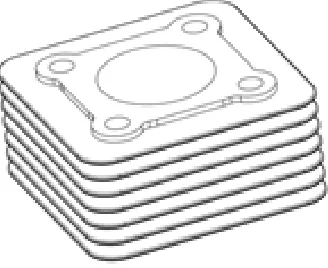
Thermal analysis of a 150 cc Spark ignition engine is performed to study the effect of material, wind speed and angle of attack of air in the heat transfer rate of the fins. Initially the basic dimensions of a 150 cc engine was measured and modelled. The modelled cylinder block along with its dimensions is presented in Error! Reference source not found.. The parameters that are varied are as follows,
1. Materials and properties a. Aluminium alloy 204:
Density - 2800 kg/m3 b. Aluminium Alloy 7075:
Thermal conductivity - 173 w/mK Specific heat - 960 J/kg 0C Density - 2700 kg/m3 c. Beryllium alloy:
Thermal conductivity - 216 w/mK Specific heat - 927 J/kg 0C Density - 1870 kg/m3 2. Wind velocity: 15 m/s, 25 m/s and 35m/s
3. Angle of attack of wind: 100 (clockwise), 50, -50 (counter clockwise) and -100
The modelled cylinder block is imported into the Computational Fluid Dynamics (CFD) analysis software (STAR CCM+). The fluid domain of dimension 650 mm x 200 mm x 220 mm is created and the cylinder block is separated from the fluid domain. Now two separate regions were created with updated fluid domain and cylinder block. The following physics were applied for solving the fluid flow,
Coupled flow
Reynolds Averaged Navier-Stokes
K-Epsilon Turbulence
Coupled energy
The cylinder block is solved with coupled solid energy. Once the physics were applied interface between cylinder block and the fluid region is created. Contact interface with in-place topology is created. The boundary conditions were applied and domain is discretised with polyhedral elements. Prismatic layer is used to capture the boundary layer flow more accurately.
The prismatic layer thickness is selected such that the wall y+ is low. The problem is solved as a steady state problem.
Meshing:
1. Polyhedral Mesh:
Polyhedral meshes provide a balanced solution for complex mesh generation problems. They are relatively easy and efficient to build, requiring no more surface preparation than the equivalent tetrahedral mesh. They also contain approximately five times fewer cells than a tetrahedral mesh for a given starting surface. Multi-region meshes with a conformal mesh interface are allowed.
2. Prism Layer Mesh:
The prism layer mesh is used with a core volume mesh to generate orthogonal prismatic cells next to wall surfaces or boundaries. This layer of cells is necessary to improve the accuracy of the flow solution
Significance of Wall y+ Value:
To understand the actual physics of wall shear stress, the flow close to the boundary layer has to be accurately captured. Since the boundary layer thickness is extremely small, the first grid point must be very close to the wall. This distance from the wall is represented as non-dimensionless wall y+.
=
=
Where,
y+ is non-dimensional distance from the wall, y is the distance from the wall (m)
is frictional velocity (m/s) is kinematic viscosity (m/s2)
is wall shear stress (Pa) is density (kg/m3)
Mesh Independence Study:
In order to avoid the grid resolution errors, three different mesh models are generated and solved. The number of cells generated is two hundred, three hundred fifty and seven hundred thousand, respectively. The results of three models are presented in the figure. The model with three hundred fifty thousand cells is selected for further simulation as further increase in the cell number doesn’t provide significant difference in the solution. By performing mesh independence study computational cost and time are reduced.
IV. OBJECTIVES
1. To make clear about the air cooling of the engine.
2. To determine the heat transfer rate of conductive and convective heat transfers. 3. To ensure the effective cooling of the engine.
4. To find the alternate possible cooling methods
V. GRAPHICAL RESULTS
Heat Transfer Rate through fin for various materials
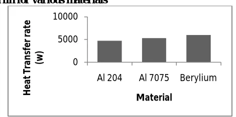
Figure 5.1: Heat Transfer Rate through fin for various materials
The heat transfer rate through the fin for different materials is presented in the above graph. From the figure it can be observed that the heat transfer rate increases with the increase in thermal conductivity. Beryllium having high thermal conductivity among the selected material has high heat transfer rate.
0 5000 10000
Al 204 Al 7075 Berylium
H
e
at
T
ra
n
sf
e
r
ra
te
(w
)
Heat Transfer Rate through fin for various wind velocities
Figure 5.2: Heat Transfer Rate through fin for various wind velocities
In the above graph, the influence of wind velocity on the heat transfer rate through fins is plotted. It can be seen that the heat transfer rate increases with the increase in wind velocity as the forced convection gets stronger with the increase in wind velocity.
Heat Transfer Rate through fin for various Angle of Attack of Wind
Figure 5.3: Heat Transfer Rate through fin for various Angle of Attack of Wind
The above graph shows the change in the heat transfer rate through the fins when the angle of attack of the wind changes. From the graph it can be seen that the angle of attack of wind has significant effect on the heat transfer rate through fins. There is a sudden increase in the heat transfer rate when the angle of attack is -50.
Minimum Fin Temperature for Various Materials
Figure 5.4: Minimum Fin Temperature for Various Materials
It can be observed that the minimum fin temperature is high for the material with high thermal conductivity.
2000 7000
15 20 25 30 35
H e at T ra n sf e r R at e (w )
Wind Velocity (m/s)
5950 6000 6050 6100 6150
-10 -5 0 5 10
H e a t Tr a n sf er R at e (w )
Angle of Attack of wind (degree)
600 700 800
Al 204 Al 7075 Berylium
VI. SIMULATION RESULTS
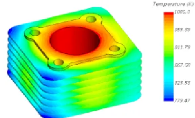
Temperature distribution at angle of attack -5o
Figure 6.1: Temperature distribution at angle of attack -5o
Temperature distribution at angle of attack 0o
Figure 6.2: Temperature Distribution at angle of attack 0o
Temperature distribution at angle of attack 5o
Figure 6.3: Temperature distribution at angle of attack 5o
VII. CONCLUSION
A 150 cc engine cylinder block has been modelled and analysed for different materials, wind velocities and angles of attack of wind. It was observed that a material with higher thermal conductivity increases the heat transfer rate, but it also increases the minimum fin temperature. When a higher thermal conductivity material is used in a particular wind velocity conduction dominates the convection. The relationship between wind velocity and heat transfer rate suggests that the fins should be designed in such a way that it performs well even at low wind velocities. It has been observed that the angle of attack of wind has a significant effect on the heat transfer rate and the average fin surface temperature. Unlike changing the material changing the orientation of the engine (changing the angle of attack of wind) provides higher heat transfer rate with lower average fin temperature.
VIII. FUTURE ENHANCEMENT
Transient analysis of engine with time dependent thermal loads and wind speed based on the vehicle speed would provide more realistic approach on heat transfer rate and average fin surface temperature
REFERENCES
[1]Abdullah H. Aiessa And Mohammed Q. Al- Odat, “ Enhancement Of Natural Convection Heat Transfer From A Fin By Triangular Perforations Of Bases Parallel And Toward Its Base”, Paper Published Oct 2009,Vol 34, Number 2B, PP 531-544
[2]Ajay paul.J,SagarChavanVijay,U.Magarajan and R.ThundilKaruppa Raj “Experimental and Parametric Study of extended fins in the optimization of internal combustion engine cooling using CFD “,paper published 2012,vol-2,PP 81-89
[3]Mr. Ashok TukaramPise and UmeshVandeoraoAwasarmol “ Investigation Of Enhancement of Natural convection Heat Transfer from Engine Cylinder With Permeable Fins” paper published Aug 2010, PP 238-247.