c
Owned by the authors, published by EDP Sciences, 2012
Experimental and numerical study on fragmentation of steel projectiles
K.G. Rakv
å
g
1,a, T. Børvik
1,2, O.S. Hopperstad
1, and I. Westermann
31 Structural Impact Laboratory (SIMLab), Centre for Research-based Innovation (CRI) and Department
of Structural Engineering, Norwegian University of Science and Technology, Rich. Birkelandsvei 1A, 7491 Trondheim, Norway
2 Norwegian Defence Estates Agency, Research & Development Department, PB 405, Sentrum, 0103 Oslo,
Norway
3 SINTEF Materials and Chemistry, Rich. Birkelandsvei 2B, 7465 Trondheim, Norway
Abstract. A previous experimental study on penetration and perforation of circular Weldox 460E target plates with varying thicknesses struck by blunt-nose projectiles revealed that fragmentation of the projectile occurred if the target thickness or impact velocity exceeded a certain value. Thus, numerical simulations that do not account for fragmentation during impact can underestimate the perforation resistance of protective structures. Previous numerical studies have focused primarily on the target plate behaviour. This study considers the behaviour of the projectile and its possible fragmentation during impact. Hardened steel projectiles were launched at varying velocities in a series of Taylor tests. The impact events were captured using a high-speed camera. Fractography of the fragmented projectiles showed that there are several fracture mechanisms present during the fragmentation process. Tensile tests of the projectile material revealed that the hardened material has considerable variations in yield stress and fracture stress and strain. In the finite element model, the stress-strain behaviour from tensile tests was used to model the projectile material with solid elements and the modified Johnson-Cook constitutive relation. Numerical simulations incorporating the variations in material properties are capable of reproducing the experimental fracture patterns, albeit the predicted fragmentation velocities are too low.
1 Introduction
In this study, the classical Taylor test is used to test and provoke fragmentation. The test was originally conceived in 1948 by Taylor [1] as a material test to determine the dynamic compressive yield stress of the material. The test procedure is to impact a blunt-nose projectile into a rigid wall, and based on post-impact measurements of the deformed cylinder, material properties are extracted based on Taylor’s analysis. It has later been shown that the Taylor test is not suitable as a material characterization test. The results from the Taylor analysis are at best ap-proximations, and it has been shown through experiments that the analysis does not predict the deformation or derive the yield strength accurately [2]. Hence, the Taylor test is used herein as a component test, and tension tests are used as material tests. Well over 400 scientific articles have been published with relation to the Taylor test [3], but only a few have investigated fracture or fragmentation in the projectile. Woodward et al. [4] identified four distinct modes of failure in the projectile during the Taylor test for high-strength steel:
1. Tensile splitting on the edge of the mushroomed end due to hoop strain exceeding the failure strain without fragments.
2. Shear fracture where a conical region separates. 3. Combined spiral shear fracture and tensile splitting
where the mushroomed material separates from the impact end of the projectile.
4. Void nucleation due to hydrostatic tension in the centre of the projectile.
ae-mail:[email protected]
Teng et al. [3] attempted to predict fracture in numerical simulations of the Taylor test using element erosion. Dif-ferent ductile fracture criteria were then compared to see how well they would model the various deformation mech-anisms. They identified a possible fifth mode of failure in the numerical simulations; sunflower-like petalling for the relatively ductile Weldox 460E steel.
Chen et al. [5] performed a study on soft steel pro-jectiles impacting a harder, but not rigid, target plate with velocities ranging from 200 − 800 m/s. They ex-perimentally identified the sunflower-like petalling mode predicted by Teng et al. They also noted an important difference between the Taylor test and their own non-penetrating experiments. With a deformable target plate the mushroomed part of the impact end consists of two parts: An inner circle with diameter approximately equal to the undeformed projectile diameter and an outer loop of material. The tensile splitting in the outer loop never crossed the interface between the parts. They noticed that the reason for the petalling is that the outer loop separates from the inner circle.
Table 1.Chemical composition of Arne tool steel.
C Mn Cr W V
0.95 1.1 0.6 0.6 0.1
two loops, supporting a triaxility cut-off for the fracture criterion proposed by Teng et al. [3], as the outer loop is in tension in the hoop direction and the inner part is in compression due to the momentum of the projectile tail. However, in the hard projectiles the shear cracks crossed the interface and generated some loose fragments and a pointed projectile nose as experienced by Woodward et al. [4]. Also, based on numerical simulations Xiao et al. [7] speculate that the deformation mechanisms for shear cracking and fragmentation are the same.
Meyer and Brannon [8] used a Weibull distribution of the fracture properties in simulations of a Behind Armor Debris experiment. They found that the statistical failure model predicted the size distribution of fragments better than a homogenous failure model. They argue that this is due to the inherent variation of the material properties in the bulk material.
The scope of this paper is to investigate whether the critical velocity for fragmentation or fracture of the pro-jectile can be identified. When the propro-jectile fragments, it loses much of its penetrating capacity and thus this critical velocity is important for design of protective structures.
2 Experimental study
2.1 Material tests
The projectiles used in the Taylor impact tests were made of Arne tool steel hardened to a nominal Rockwell C value of 52. The alloying contents are listed in Table 1, and similar projectiles have been used in previous impact tests, e.g. [9] [10]. Axisymmetric specimens with a gauge length of about 40 mm and diameter of 6.0 mm were spark eroded from hardened projectiles. Three parallel tests were carried out at room temperature. The cross-head velocity of the tension machine during testing was 1.5 mm/min, which corresponds to an average strain rate in the gauge area of 6×10⁻⁴s−1. The force and the diameter at
minimum cross-section of the specimen were continuously measured until fracture. The latter was made possible using a purpose-built measuring rig with two perpendicular lasers that accurately measured the specimen diameter. The lasers were installed on a mobile frame to ensure that the diameter during straining always was measured at minimum cross-section. The Cauchy (true) stress and the logarithmic (true) plastic strain were calculated as
σ=F A,
p= lnA0
A −2ν σ
E (1) whereFis the force,A0= π4D20is the initial cross-section
area,D0is the initial diameter of the gauge section,νis the
Poisson ratio andEis the Young modulus. Due to possible variations in stress and strain over the cross-section,σand should be considered as average values. The current area
Fig. 1.True stress versus true plastic strain in uniaxial tension for Arne tool steel hardened to HRC 52.
of the cross-section is A=π
4D1D2 (2)
where D1 and D2 are the diameters as measured by
the lasers. Note that the measured Cauchy stress σ is equal to the von Mises equivalent stressσin the uniaxial tension test because the specimens fractured before the onset of necking. The Cauchy stress – logarithmic plastic strain curves until fracture are shown in Figure 1. The yield stress, the peak stress and the fracture strain varies considerably between parallel tests. Dynamic tensile tests on unhardened specimens were also conducted in a split-Hokinson tension bar (SHTB). In these tests the strain rate was varied between 100 and 1000 s−1. The strain-rate sensitivity of the Arne tool steel was found to be rather low. Since it is assumed that the strain-rate sensitivity decreases with increasing hardness, the possible effects of strain-rate sensitivity will be neglected in this study.
2.2 Taylor impact tests
A compressed gas gun was used to accelerate the sabot-mounted projectiles, and the impact process was recorded by a high-speed camera. Laser curtains were used to measure the impact velocities and trigger the high-speed camera. The cylindrical and blunt-nosed projectiles had nominal length 80 mm, diameter 20 mm, mass 197 g and hardness HRC 52, and they impacted a cylindrical target plate with diameter 100 mm, thickness 50 mm and hard-ness HRC 60. The target plate was firmly attached to a larger support steel plate with thickness 15 mm, which in turn was bolted to a rigid frame. The distance from the muzzle of the barrel to the target plate was about 2.0 m.
(a)
(b)
(c)
(d)
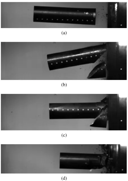
Fig. 2.High speed camera photographs of the projectiles after impact with the target plate for velocites ranging from 124.4 to 153.7 m/s. (a) 124.4 m/s; (b) 132.9 m/s; (c) 134.7 m/s and (d) 153.7 m/s.
major plane≈45◦to the longitudinal axis of the projectile. At an impact velocity of 154 m/s and above, the projectile shattered into a number of fragments.
The experimental results presented in Figure 2 is an excerpt from a larger test series with velocities ranging from 120 to 300 m/s. An ongoing metallurgical investiga-tion of the fragmented projectiles indicates that projectiles that fractured at higher velocities have a primary shear fracture similar to the one observed in Figure 2(b) and secondary cleavage fracture which is responsible for the fragmentation. An excerpt of the fractography that was obtained from a hardened projectile that fragmented at 200 m/s is shown in Figure 3.
The variety of fracture surfaces present in the frag-ments from the projectile, as shown in Fig. 3, implicate that there are several fracture mechanisms active in the fragmentation process. The fracture surface in Figure 3(a) shows a typical quasi-cleavage fracture with river patterns (cleavage), but also evidence of ductile behaviour (i.e. voids). This fracture surface is from a fragment that is away from the front end. Figure 3(b) clearly shows what might be melted material, possible due to extreme temperatures in the shear zone. Figure 3(c) shows the brittle surface of the primary shear fracture. The variety in fracture modes complicates the fracture modelling both in terms of choice of method and input parameters. Thus, the focus of the numerical study will be to recreate a shear fracture similar to the one shown in Figure 2(b).
(a)
(b)
(c)
Fig. 3.SEM fractography of a fragmented projectile showing different fracture surfaces in the projectile. (a) Quasi-cleavage; (b) Possible melted material and (c) Brittle fracture in the shear zone.
3 Numerical study
Table 2.Nominal thermoelastic-thermoplastic material proper-ties for steel.
ρ[kg/m3] E[MPa] ν χ C
p[J/kgK] Tm[K]
7850 210000 0.3 0.9 452 1743
erosion, cohesive zones models or node splitting. Cohesive zone modelling was tried as a first approach, including a thorough fracture mechanics test program consisting of dynamic Charpy testing and quasi-static three-point bending tests. This approach turned out to be unsuccessful, partly due to difficulties and uncertainties with the fracture testing. Problems were also encountered with the cohe-sive models as implemented in LS-DYNA. Thus, element erosion was chosen because of its simplicity. Element erosion also eliminates the need of establishing a fracture pattern from the outset, which is needed for cohesive zone modelling. Node splitting was not considered here, as it is in general not available for 3D simulations in commercial FE codes.
The projectile material was modelled with solid ele-ments using the modified Johnson-Cook constitutive re-lation with Voce hardening and the Cockcroft-Latham failure criterion [11], and the true stress-strain data from the tensile tests (Figure 1) was used to obtain the mate-rial parameters given in Table 3. Nominal thermoelastic-thermoplastic material properties for the steel used are shown in Table 2. The von Mises equivalent stressσ as a function of equivalent plastic strainis expressed as
σ=
σ0+
2
i=1
Qi1−e(−Ci)
1+ ˙ ˙ 0
c
1−(T∗)m (3) where ˙is the equivalent plastic strain rate and ˙0is a
user-defined reference strain rate. The constantσ0 defines the
initial yield strength of the material, whereas Qi andCi, i = 1,2, define the strain hardening. The homologoeus temperature is defined as
T∗= T−Tr
Tm−Tr (4) where T is the absolute temperature, Tr is the ambient temperature and Tm is the melting temperature. The rate sensitivity is governed by the constantc, whilemdefines the thermal softening behaviour. In this studycis set equal to zero due to the low strain rate sensitivity of the base material, andmis set to unity. The temperature change due to adiabatic heating may be calculated as
∆T =
0
χρσ
Cpd (5) where ρ is the material density, Cp is the specific heat andχis the Taylor-Quinney coefficient that represents the proportion of plastic work converted into heat. Finally, an element is eroded (all stresses set equal to zero) when
D= 1 Wc
0
σ1d=1 (6)
(a)
(b)
(c)
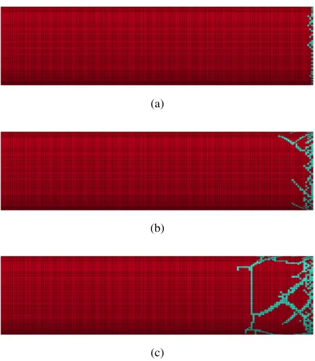
Fig. 4.Typical fracture pattern evolution in projectile simulated with homogeneous material. Deleted elements are shown on the undeformed configuration. (a) 110 m/s; (b) 115 m/s and (c) 120 m/s.
where D is the damage variable, σ1 = max(σ1,0) is
positive values of the maximum principal stress and Wc is the fracture parameter.
In the numerical analyses a characteristic element size of 0.5×0.5×0.5 mm3 was used, which gives a total of
240000 elements in the projectile. A contact formulation that allows for self-contact between newly created surfaces (i.e. the two surfaces of a propagating crack) is used both as contact between the projectile and the target plate and as self-contact in the fragmenting projectile. The target plate is modelled as a purely elastic steel. In the experiments, no indentation was found in the target plates at the velocities presented here, so it is reasonable to assume that the yield stress of the target plate was not exceeded.
3.1 Numerical results
As a first approach three sets of separate simulations with a homogeneous material from each tensile test were performed. Material parameters from tension tests 1 and 2 gave a fragmentation velocity of 120 m/s, while the parameters from tension test 3 gave a fragmentation ve-locity of 115 m/s. However, none of these simulations reproduced the shear fracture mode from the experiments. The fracture pattern evolution from 110 m/s to 120 m/s for the parameters from tension test 1 is shown in Figure 4.
Table 3.Material model parameters from the three tension tests.
Test σ0[MPa] Q1[MPa] C1 Q2[MPa] C2 Wc[MPa]
1 1134.4 959.3 18.3 324.0 690.3 23.0
2 1285.2 1081 20.0 315.9 1652 18.7
3 1660.4 1195 20.8 123.0 4591 14.5
Fig. 5.Distribution of material parameters.
(a)
(b)
(c)
Fig. 6.Fracture pattern evolution in distributed projectile mater-ial. Deleted elements are shown on the undeformed configuration. (a) 110 m/s; (b) 115 m/s and (c) 120 m/s.
This approach was capable of capturing the shear frac-ture pattern, although the fragmentation of the projectile happened at a lower velocity than in the previous analyses. Figure 6 shows the fracture pattern evolution of a projectile with randomly distributed material characteristics at a velocity ranging from 110 m/s to 120 m/s.
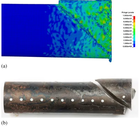
Both the single shear fracture at 132.9 m/s (Figure 2(b)) and the double shear fracture at 134.7 m/s (Figure 2(c)) from the experiments are reproduced by this model, as well as the transition to fragmentation at the highest impact velocities. However, the critical velocity for projectile fracture is lower than the experimental velocities and also lower than for the simulations with a homogeneous material. The reason for this is probably the very crude way of distributing the material parameters, and a more thorough distribution should be implemented directly into the material model. A direct comparison of the primary shear fracture is shown in Figure 7, where it is seen that the numerical shear crack is very similar to the experimental
(a)
(b)
Fig. 7. Comparison of primary shear crack from simulations (110 m/s) and experiments (132.9 m/s). (a) Deformed configu-ration with fringes of the damage variable D from numerical simulation at 110 m/s and (b) Photo of experimental obtained shear crack at 132.9 m/s.
Fig. 8.Fracture pattern evolution in distributed projectile material with refined mesh. Deleted elements are shown on the unde-formed configuration.
one, down to the initiation point and the lip at the end of the crack.
An important aspect to consider when using element erosion is the lack of an intrinsic length scale, which makes convergence unreliable [12]. Thus, the simulation with distributed material properties at 110 m/s was carried out with an element size of 0.25×0.25×0.25 mm3 in the
full-scale numerical simulations. Also the change in mass due to eroded elements is compared for the two analyses showing that the change is 5% for both analyses.
4 Conclusion
In this paper an experimental and numerical study on the fragmentation of hardened steel projectiles during impact has been presented. To provoke fragmentation, classical Taylor impact tests were carried out. Here, projectiles hardened to a Rockwell C value of 52 were fired into a hardened target plate, and the transition impact velocity from plastic deformation to fragmentation in the projectile was determined. Tensile tests were conducted to calibrate a proper constitutive relation and a fracture criterion in an attempt to numerically capture the fragmentation process. A metallurgical inspection of the fragments shows that there are many different fracture mechanisms present in the hardened material. It also indicates that the primary frac-ture is a shear fracfrac-ture, supporting Xiao et al. hypothesis that the deformation mechanisms for shear cracking and fragmentation are the same [6]. A rather crude method to allow for the stochastic properties of the hardened material is shown to reproduce the shear crack pattern in a much better way than analyses with a homogeneous material. However, the fragmentation velocity is lowered by this approach, so further work is needed to develop a proper way to distribute the material parameters.
References
1. G. Taylor.Proc. R. Soc. Lond. A 194, 289-299 (1948) 2. W. Johnson.Impact Strength of Materials, (1972) 3. X. Teng, T. Wierzbicki, S. Hiermaier, I. Rohr.
Inter-national Journal of Solids and Structures 42, (2005) 2929–2948
4. R.L. Woodward, R.G. ODonnell, C.J. Flockhart. Jour-nal of Materials Science27, (1992) 6411–6416 5. X.W. Chen, G. Chen, F.J. Zhang. Experimental
Me-chanics48, (2008) 335–354
6. X. Xiao, W. Zhang, G. Wei, Z. Mu. Materials and Design31, (2010) 4913–4920
7. X. Xiao, W. Zhang, G. Wei, Z. Mu, Z. Guo. Materials and Design32, (2011) 2663–2674
8. H.W. Meyer Jr., R.M. Brannon. International Journal of Impact Engineering42, (2012) 48–58
9. T. Børvik, O.S. Hopperstad, M. Langseth, K.A. Malo. International Journal of Impact Engineering28, (2003) 413–464
10. T. Børvik, M. Langseth, O.S. Hopperstad, K.A. Malo. International Journal of Impact Engineering22, (1999) 855-886
11. T. Børvik, O.S. Hopperstad, T. Berstad, M. Langseth. European Journal of Mechanics - A/Solids20, (2001) 685–712