63
Analysis of Effect of Different Process Parameters on the
Properties of the Component Manufacture Using FDM
Machine
Pawan V Mulkarwar
1, Abhijit D. Munishwar
2, Prof. Ashish M Wankhade
3, Prof. Mansur N Syed
4Department –Mechanical Engineering
1,2,3,4Affliation Name-Student of Jawaharlal Darda Institute Of Engineering &Technology ,Yavatmal
1Affliation Name-Student of Jawaharlal Darda Institute Of Engineering &Technology ,Yavatmal
2Affliation Name-Asst.Prof Of Jawaharlal Darda Institute Of Engineering &Technology ,Yavatmal
3Affliation Name-Asst.Prof Of Jawaharlal Darda Institute Of Engineering &Technology ,Yavatmal
4Email Address [email protected]
1Abstract- The rapid prototyping is an emerging technology in developing the physical prototypes from the 3D cad models by using the additive process with layers. FDM is one such RP technique which can build parts using layer by layer deposition technique using thermoplastic building material according to numerically defined cross sectional geometry. The quality of FDM produced parts is significantly affected by various parameters like build orientation, road width, air gap etc. This dissertation work aims to study the effect of three process parameters such as Road width, Air gap and sample orientation on properties. To achieve this the sample machine part were manufactured at different orientation (0o,45o,90o) at min, med, max road width and air gap. Specimens is further analyzed for accuracy, surface finish and build time. Results are tabulated and are shown graphically representation.
Index Terms-Minimum, Medium, Maximum
1. INTRODUCTION:
Measures to improve the efficiency of production processes always include the application of new and innovative manufacturing methods. Therefore, in recent years, applications of the rapid technology turned out to be potentials of the modern product development process [1].compared with traditional material removing method, rp technology is an additive material method based on layer manufacturing (lm) technique. Rp’s additive nature allows it to create objects with complicated internal features that cannot be manufactured by other means. In all commercial rp processes, the part is fabricated by deposition of layers contoured in a (x-y) plane two dimensionally. The third dimension (z) results from single layers being stacked up on top of each other, but not as a continuous z-coordinate. Therefore, the prototypes are very exact on the x-y plane but have stair-stepping effect in z-direction. In recent decades, rp technologies have been widely developed and used in different applications, and even being applied as a direct manufacturing route to
64 air gap(Min, Med, Max) separately by the rapid
prototyping technique(FDM).Then we will get the readings of different parameters like build time, support material required, model material required for above orientation. Also we will test the above prototypes for surface roughness, accuracy and tabulate the readings. After analyzing the readings we will conclude the effect of process parameters on properties of model and will compromises at better orientation.
2. LITERATURE REVIEW:-
Alexander et al. developed an accuracy calculation model and the methodology for creating the cost model. Cusp height is used to measure the accuracy of a part. The part orientation that minimizes part accuracy, build time and the amount of support material selected. The accuracy is calculated using the cusp height that considers the area of each part in the stereo lithography. The best orientation is chosen in terms of the user from the results calculated.
The ability to select the optimal orientation of buildup is one of the critical factors since it affects the part surface quality, accuracy, build time and part cost. Various factors to be considered in optimization of build orientation for FDM are build material, support material; build up time, surface roughness and total cost. Experiments were carried out and results are analyses for varying build orientation for primitive geometries like cylinder. A mathematical
model was developed after validating the theoretical values of surface roughness with measured values. This helps in reducing experimental work and improves possibilities of virtual simulation of rapid prototyping parts (chenget. al.1995)
This paper presents a generic system that performs a computer-aided optimization of part orientation in consideration of the mentioned factors of influence as well as related effects. The proprietary development of the implementation of the presented approach is based on the paradigm of object-oriented and generic programming and therefore versatile. A vertical orientation would result in good part quality except the holes but also in a high number of layers and therefore in longbuild time. A horizontal orientation would lead to a cost-effective build time but also to insufficient dimensional accuracy.(S. Danjou 1, P. Koehler et. al.2009).
Paper represent characterize some of the properties of Stratasys. Fused Deposition Modeling (FDM) process, as well as the effects of varying some of the build parameters. Series of Samples were manufactured at FDM m/c and tested for load using inston load frame. In the tension tests, the predicted behavior does not correlate very well with the measured behavior when the correct material properties are used. However, when the tensile strength in the transverse direction with a negative airgap is substituted into the no airgap material properties, the predictive model is quite accurate (John Michael Brock et. al.2000).
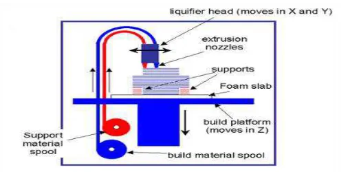
65 occurs by a thermally-driven diffusion bonding process
during solidification of the semi-liquid extruded fibre.
2.2 Advantages:-
(1)Quick and cheap generation of models
(2)There is no worry of exposure to toxic chemicals,
lasers or a liquid chemical bath.
2.3Disadvantages:-
(1)Restricted accuracy due to the shape of material used, wire is 1.27 mm diameter.
Fig. 1:- FDM Process
3. MATERIAL:- ABS is an ideal material for conceptual modeling, functional prototyping and direct digital manufacturing. Acrylonitrile - Butadiene - Styrene (ABS) identifies a family of engineering thermoplastics with a broad range of performance characteristics. The copolymeric system is alloyed to yield the optimum balance of properties suited to the selected end use.
3.1 ACRYLONITRILE - Imparts chemical resistance and rigidity.
3.2 BUTADIENE - Endows the product with impact strength, toughness and abrasion resistance.
3.3 STYRENE – Contributes to the lustre, ease of processing and rigidity.
The outstanding properties of ABS are:
1.High impact ,strength and ductility, which combine to give exceptional toughness.
2. Good chemical resistance. 3. Abrasion resistance.
4 High strength solvent weld jointing which allows efficient system assembly and modification.
5. Rubber Ring joint methods, allowing compatible systems jointing techniques.
6. Nontoxic and non-taint properties. 7. Withstands aggressive ground waters. 8. High strain tolerance for buried applications. 9. Good resistance to ultraviolet light.
66
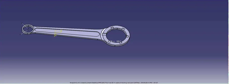
Fig 2: General view connecting rod
4. METHODOLOGY:- The methodology of the project is described in following steps:-
4.1 Selection of specimen:- We selected the simple m/c part i.e connecting rod of two stroke engine as specimen.
4.2 Design of specimen:-After selecting the specimen, we measured out the actual dimensions of specimen. Optimized Connecting Rod has been modeled with the help of CATIA, in general we had perform the reverse engg. The Orthographic and Solid Model of optimized connecting rod is shown below.
4.3 FABRICATION OF MODEL:- Actual fabricated prototypes of specimen at different build orientation i.e 0o,45o,90 along with different process parameters i.e roadwidth and air gap Min(00,450,900), Med(00,450,900), Max(00,450,900) on FDM TITAN T1 machine. ABS was used as Raw material for fabrication of model. We fabricated nine models i.e for each angle, Min(00,450,900),Med(00,450,900),Max(00,450,900) road width and air gap was varied.
5. OBSERVATION AND ANALYSIS:- Fabricated model at 00,450,900 with Min,Med,Max, roadwidth and airgap and the reading for orientation at an interval of 450each an taken from system software. Fabricated models were tested for surface roughness
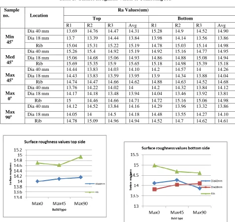
67 Table 1:- Surface Roughness Values of Connecting rod
Table 1:- Surface Roughness Values of Connecting rod
Sample
no. Location
Ra Values(um)
Top Bottom
R1 R2 R3 Avg R1 R2 R3 Avg
Min 45o
Dia 40 mm 13.69 14.76 14.47 14.31 15.28 14.9 14.52 14.90 Dia 18 mm 13.7 13.39 14.44 13.84 13.98 14.14 13.56 13.86 Rib 15.04 15.31 15.22 15.19 14.78 15.03 15.14 14.98
Med 45o
Dia 40 mm 15.26 15.4 14.92 15.19 14.92 15.16 14.77 14.95 Dia 18 mm 15.06 14.68 15.06 14.93 14.86 14.88 15.08 14.94 Rib 15.69 15.35 15.9 15.65 15.18 14.98 15.39 15.18
Max 45o
Dia 40 mm 14.44 13.83 14.03 14.10 14.2 14.57 14 14.26 Dia 18 mm 14.43 13.83 13.59 13.95 13.9 14.34 13.88 14.04 Rib 14.74 14.47 14.66 14.62 14.88 14.63 14.52 14.68
Max 0o
Dia 40 mm 13.76 14.22 14.02 14 14.2 14.32 13.84 14.12 Dia 18 mm 14.17 14.18 13.48 13.94 14.04 13.46 13.92 13.81 Rib 15 14.46 14.66 14.71 14.72 15.16 15.06 14.98
Max 90o
Dia 40 mm 14.12 14.52 13.84 14.16 14.29 13.96 13.32 13.86 Dia 18 mm 14.05 14 14.5 14.18 14.48 13.55 14.27 14.10 Rib 14.78 15.09 14.96 14.94 14.52 14.7 14.62 14.61
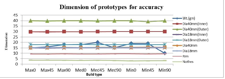
68 Table 2:- Dimension of prototypes for accuracy
Sr.no Build
Type
Wt. (gm)
Dia 40 mm Dia 80 mm Dia
40mm
Dia 18mm
Rim Notches
Inner Outter Inner Outter
1 Max 0o
15 29.73 39.90 14.81 18.03 15.27 15.25 9.42 3.68
2 Max 45o
16 29.60 39.77 14.77 17.90 15.25 15.24 9.35 3.74
3 Max 90o
18 29.81 39.90 14.83 17.88 15.43 15.33 9.54 3.62
4 Med 0o
18 29.78 39.92 14.84 18.06 15.30 15.30 9.43 3.50
5 Med 45o
20 29.88 39.83 14.81 17.94 15.50 15.28 9.38 3.56
6 Med 90o
15 29.90 39.94 14.95 17.92 15.45 15.34 9.57 3.36
7 Min 0o
19 29.95 39.94 14.90 18.11 15.48 15.33 9.60 3.14
8 Min 45o
19 29.96 39.03 14.98 18.05 15.69 15.35 9.45 3.23
9 Min 90o
69 Table 3:- Material and time required for different orientation
Sr. no. Build type Time req.(min) Material req.
Maximum
1. Max00 1.22 1.06
2. Max150 1.17 1.06
3. Max300 1.18 1.07
4. Max450 1.18 1.07
5. Max600 1.12 1.06
6. Max900 1.11 1.06
Medium
1. Med00 1.12 1.27
2. Med150 1.09 1.27
3. Med300 1.11 1.27
4. Med450 1.09 1.29
5. Med600 1.08 1.28
6. Med900 1.08 1.27
Minimum
1. Min00 1.39 1.29
2. Min150 1.31 1.29
3. Min300 1.29 1.25
70
5 Min600 1.32 1.29
6. Min900 1.21 1.29
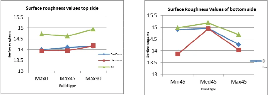
6. RESULT AND CONCLUSION:-
This Paper represent an approach that determines optimal build orientation for FDM, Also the effect of process parameters like Road width, Air gap, build material, support material on the properties of component i.e Accuracy, Surface roughness and build time. The minimization of Build material and support material is also implicitly included in work. The values of build time, Accuracy and surface roughness are determined for varying Road width and Air gap, Min(00,450,900),Med(00,450,900),Max(00,450,900) at each angle. From the computed Values of Build time, Model material, Accuracy, Surface roughness, Support material Required, its effect on build orientation and optimal orientation is determined.
71 surface finish of maximum road width and air gap
prototypes is excellent and it decreases with increases in angles (00,450,900). Form the accuracy point of view better accuracy is obtained at minimum road width and air gap.
REFERENCE:-
[1] Part orientation and build cost determination in layered manufacturing’, P. Alexander, S. Allen, D. Dutta, , Volume 30 (5) (1998) ,pg. 343–356. [2] Multi objective optimization of build orientation
for rapid prototyping with fused deposition modeling (FDM)’,G. R. N. Tagore, Swapnil. D. Anjikar, A. Venu Gopal, Department of Mechanical Engineering, National Institute of Technology, Warangal, Research Scholar, Dept. Of Mechanical Engineering, NIT–Warangal, INDIA.
[3] Cheng, W.; Fuh, J.; Nee, A.; Wong, Y.; Loh, H.; Miyazawa, T.Multi-Objective Optimization ofPart-Building Orientation in Stereolithography,Rapid Prototyping Journal, 1995, 1 (4), pp. 12-23.
[4] ‘A volumetric approach to part-build orientations in rapid prototyping’, W. Rattanawong, S.H. Masood, P. Iovenitti, , Journal of Materials Processing
[5] Fused deposition modeling material properties characterization, Michel brock, 2000.
[6] ‘Rapid prototyping technologies, applications and part deposition planning’, Pulak M. Pandey, Department of Mechanical Engineering Indian Institute of Technology ,Delhi.
[7].‘Part Deposition Orientation in Fused Deposition Modeling’, Thrimurthullu, K., Pandey, P.M., Reddy, N.V. (2004), International Journal of Machine Tools and Manufacture,2004, 44, pp. 585-594.
[8]‘Investigation of The Effect of Various Build Methods on the Performance of Rapid Prototyping (Stereolithography)’. Williams, R.E., Komaragiri., S.N., Melton, V.L., Bishu, R.R. (1996), Journal of Materials Processing Technology, 61, (1-2), pp.173-178.