Technology (IJRASET)
©IJRASET 2015: All Rights are Reserved
420
Design of Brushless DC Motor with Fuzzy Logic
Controller
Vikramarajan Jambulingam
Electrical and Electronics Engineering, VIT University, India.
Abstract - Actually brushless DC motor is the alternate motor for traditional motors and also comparatively brushless DC motor has improved performance in speed, torque, efficiency and electromagnetic torque. In this paper the three phase brushless DC motor model is designed with fuzzy logic controller and tested in MATLAB software. The Fuzzy logic controller is used to control the speed of the brushless DC motor. On the other hand parameters like Back EMF, current, speed and torque are evaluated for the designed models of BLDC motor.
Keywords - Brushless DC motor, Fuzzy logic controller, PMBLDC.
I. INTRODUCTION
The replacement for conventional DC motor is BLDC motor in many cases. The characteristic of DC motor is retained by BLDC motor except brushes and commutator. To provide large amount of torque for a wide range of speed BLDC motor suits the most with high performance. Actually for applications that require high power, high reliability and high efficiency BLDC motor is the ideal choice.
A small BLDC motor is used in hard disk drives and large BLDC motor is used in electric vehicles. In BLDC motor physical commutator is not necessary because the electric current powers the permanent magnet that causes rotation in motor. So current commutation takes place because of solid state switches. In this case commutation happens electronically. Most commonly used BLDC motors are three phases rather than two phase BLDC motor.
Due to the rotor rotation voltage is induced in the stator winding called back-EMF of BLDC motor. So torque is primarily influenced by back-EMF of BLDC motor. In case size of the motor and torque delivered ratio is higher so the critical factors are space and weights in certain application to make it useful. When practical speaking the torque ripple exit mainly due to imperfection emf, ripple current and phase current commutation. Due to the magnet size and shape of the BLDC motor the imperfection emf is occurred. On the other side hysteresis and PWM control generates ripple in current. The Bimbra [1] has explained the generalized machine theory.
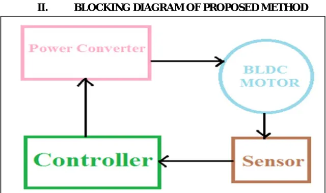
[image:2.612.146.466.504.694.2]II. BLOCKING DIAGRAM OF PROPOSED METHOD
Technology (IJRASET)
©IJRASET 2015: All Rights are Reserved
421
The block diagram of brushless dc motor with its speed controller is shown in [Figure.1].It consist of four main parts they are BLDC motor, sensors, controller and power converters. The power is transformed from source to BLDC motor through converter. So the BLDC motor in turn converts electrical energy in to mechanical energy. To the power converter gate signal is applied on the basis of rotor position.
III. WORKING PRINCIPLE OF BLDC MOTOR
[image:3.612.147.466.235.425.2]One after another the BLDC motor’s electronic commutator energizes the stator coils and generates a rotating electric field that ‘drags’ the rotor around with it. N “electrical rotations” equates to one mechanical rotation, where N is the number of magnet pairs. To indicate the relative position of stator and rotor to the controller three phase effect sensors are embedded in the stator of the three phase brushless DC motor. The hall sensor helps brushless DC motor to energize the winding in a correct sequence and at the correct time.Constructionally the all sensor is mounted on the non driving side of the system [Figure.2].
Figure 2: Hall sensors are embedded in the stator of a BLDC motor
The high or low signal is generated during the rotor magnetic poles passes the hall sensors by combining the signals from the three sensors. Due to the movement of the winding through the associated magnetic field the potential voltage is generated by the electrical motors and it can be called as electromotive force. As per Lenz’s law the magnetic field which opposes original change in flux will give rise in winding current. In general this means electromotive force tends to resist the rotation of the motor and referred as back electromotive force.
The Baldursson [2] has developed brushless DC motor modelling and control. Padmaraja [3] has developed the fundamentals of brushless DC motor. A new simulation model is developed by Jeon [4].For complete MATLAB modelling Simulink user’s guide is helpful [5].
IV. BLOCK DIAGRAM OF FUZZY LOGIC CONTROLLER AND ITS WORKING
In developing sophisticated control system fuzzy logic has become one of the most successful technologies. The variety and number of fuzzy logics are continuously improving in the recent years due to implementation is simple and inexpensive controllers. The Fuzzy logic controller techniques are presented in detail by Elmas, Silva and KO [6], [7], [8]. In 1960’s lotfi zadeh has introduced the fuzzy set theory. The fuzzy set theory is an approximately reasoning, approximate information and uncertainty to generate decision. There are two main reasons for selecting fuzzy logic controller. They are as follows;
Technology (IJRASET)
©IJRASET 2015: All Rights are Reserved
422
Figure.3. Block diagram of fuzzy logic controller
The traditional methods are complex to model accurately for complex mathematical equations and also this type of traditional system becomes infeasible. But fuzzy logic provides a feasible method. Therefore defining the operational characteristics of such system is simple. The fuzzy logic controller configuration is shown in [Figure.3]. The main components of fuzzy logic controllers are as follows:
Fuzzification Fuzzy inference Defuzzification
A. Fuzzification
Fuzzification has the process of mapping the multiple measured crisp inputs with fuzzy membership function. Fuzzification is to converts input data in to suitable value .This value can be considered as label of fuzzy sets. Fuzzification performs a scale mapping which transfers the input variables in to corresponding universe of discourse. The [Figure.4] shows the fuzzy membership functions in the form of trapezoidal, triangle and bell membership functions.
(a)
Technology (IJRASET)
©IJRASET 2015: All Rights are Reserved
423
(c)
Figure.4 Triangle (a), Trapezoidal (b) and Bell membership function (c) Triangle membership function is defined as,
/1 /1 /1 /2 /1 /3 /2 /2 /3 /2
,
( )
,
.{1}
0
,
i a
a i a
a a
a i
i a i a
a a
u V
V
u V
V
V
V
u
u
V
u V
Eq
V
V
otherwise
Limits
[
V
a/1,
V
a/2,
V
a/3]
Trapezoidal membership function is defined as,
/1 /1 /2 /2 /1 /2 /3 /4 /3 /4 /4 /3
1
( )
.{2}
0
i a
a i a a a
a i a i
a i
a i a a a
u V
V
u
V
V
V
V
u
V
u
Eq
V
u
V
u
V
V
V
otherwise
Limits
[
V
a/1,
V
a/2,
V
a/3,
V
a/4]
Bell membership function is defined as,
2
1
( )
.{3}
1
i m i pu
Eq
u X
w
Xp-Mid PointW-Width of bell membership function
1
Technology (IJRASET)
©IJRASET 2015: All Rights are Reserved
424
Figure.5 Fuzzy membership functions for seven levels.
B. Fuzzy Inference
Fuzzy inference is nothing but by using fuzzy logic there is a process of mapping the given input to the output and on the basis of this mapping decision are made or pattern discerned.
C. Defuzzification
The output variables are the output of the interference mechanism. The internal fuzzy output variables are converted in to crisp values by the fuzzy logic controller so that system can use these variables. Hence it is called as defuzzification.
V. FLC SPEED CONTROL ALGORITHM
Step 1: The brushless DC motor speed signal is sampled. Step 2: Calculate speed error.
Step 3: Calculate change in speed error.
Step 4: Determine fuzzy sets and membership for speed error.
Step 5: Determine fuzzy sets and membership for change in speed error. Step 6: Finding control action as per fuzzy rule.
Step 7: Calculate
iqsStep 8: Sending control command to the system after calculation of
iqs. Input and output variables of fuzzy membership function are selected as follows, PB-Positive BigPM-Positive Medium PS-Positive Small NB-Negative Big NM-Negative Medium NS-Negative Small Z-Zero
Input variables:
Technology (IJRASET)
©IJRASET 2015: All Rights are Reserved
425
Value of change in speed error,
1
ce
1
Output variables:Change in torque reference current,
1
iqs
1
Because of the best control performance and simplicity the triangular shaped function are chosen as membership functions. TABLE I
E/CE NB NM NS ZO PS PS PB NB NB NB NB NB NM NS ZO NM NB NB NB NM NS ZO PS NS NB NB NM NS ZO PS PM ZO NB NM NS ZO PS PM PB PS NM NS ZO PS PM PB PB PM NS ZO PS PM PB PB PB PB ZO PS PM PB PB PB PB
Table.1.Rule based table
VI. MATHEMATICAL MODELLING OF THE BLDC MOTOR
.(1)
a b c
a a a a ab ac a
t t
di
di
di
V
i R
L
M
M
e
Eq
d
d
dt
.(2)
b a c
b b b b ba bc b
t t
di
di
di
V
i R
L
M
M
e
Eq
d
d
dt
.(3)
c b a
c c c c cb ca c
t t
di
di
di
V
i R
L
M
M
e
Eq
d
d
dt
Where,
R R R
a,
b,
c-Stator resistance of phase a, b and c.,
,
a b c
L L L
- Stator inductance of phase a, b and c., ,
a b c
i i i
-Stator current of phase a, b and c.,
,
a b c
V V V
-Voltages of phase a, b and c.a b c
R
R
R
R
-Mutual inductance between phases,
,
a b c
L L L
-Stator self inductance of phase a, b and c. In this case,L
a
L
b
L
c
L
ab ac bc ba ca cb
M
M
M
M
M
M
M
Assuming three phase balanced system, all phase resistance are equal.
a b c
R
R
R
R
Let us rearrange the above equations 1, 2 and 3. We get,
.(4)
a b c
a a a
t t
di
di
di
V
i R
L
M
M
e
Eq
d
d
dt
.(5)
b a c
b b b
t t
di
di
di
V
i R
L
M
M
e
Eq
d
d
dt
.(6)
c b a
c c c
t t
di
di
di
V
i R
L
M
M
e
Eq
d
d
dt
Technology (IJRASET)
©IJRASET 2015: All Rights are Reserved
426
Let us neglect mutual inductance in equations 4, 5 and 6. We get,
.(7)
aa a a
t
di
V
i R
L
e
Eq
d
.(8)
bb b b
t
di
V
i R
L
e
Eq
d
.(9)
cc c c
t
di
V
i R
L
e
Eq
d
VII. TORQUE GENERATION
Theoretical motor constant ‘Kt’ is the product of torque and supply current ‘I’.
a b c
T
T
T
( ) ( ) ( ) ( )
t motor t a t b t c
K
K
K
K
motor a b c
i
i
i
i
-Angle,
,
a b c
T T T
-Total torques*
2
d
P
dt
The generated electromagnetic torque is given by,
[
a a b b c c]
ee i
e i
e i
T
in N-M{
( )
( )
( )
e t a a b b c c
T
K
f
i
f
i
f
i
1
e
d
J
B
T
T
dt
The relation between angular velocity and angular position is given by,
*
2
d
P
dt
1T
-load torque
-Motor inertia B-Damping Constant P-Number of polesVIII. SIMULATION MODEL OF THE BLDC MOTOR
TABLE II Voltage (Vdc) 160 volts
Damping constant (Tload) 0.02 N-M/rad/sec
Resistance (R) 0.7 ohms Inductance (L) 2.72 mH
Moment of inertia (J) 0.000284Kg-m/sec2 Number of poles 4
Number of phases 3
Technology (IJRASET)
[image:9.612.91.544.86.401.2]©IJRASET 2015: All Rights are Reserved
427
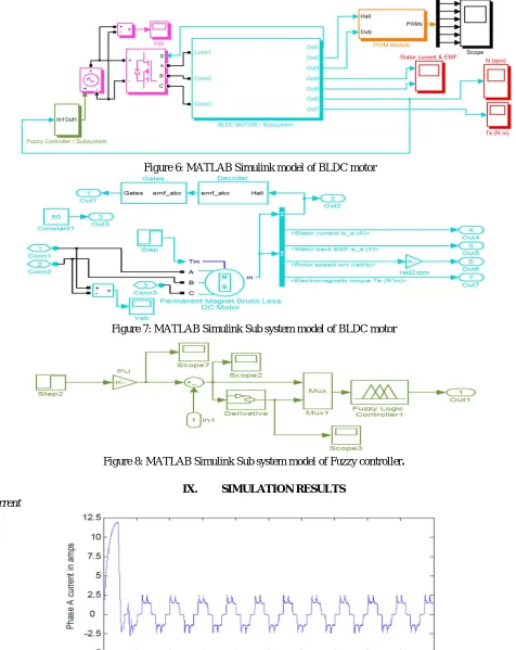
Figure 6: MATLAB Simulink model of BLDC motor
[image:9.612.72.548.87.686.2]Figure 7: MATLAB Simulink Sub system model of BLDC motor
Figure 8: MATLAB Simulink Sub system model of Fuzzy controller. IX. SIMULATION RESULTS
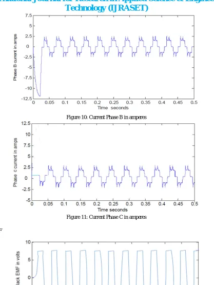
A. Current
[image:9.612.109.479.531.707.2]Technology (IJRASET)
©IJRASET 2015: All Rights are Reserved
428
[image:10.612.99.516.52.607.2]Figure 10: Current Phase B in amperes
Figure 11: Current Phase C in amperes
[image:10.612.126.493.513.686.2]B. Back EMF
Technology (IJRASET)
©IJRASET 2015: All Rights are Reserved
429
[image:11.612.50.517.41.715.2]Figure 13: Back EMF Phase B in Voltages
Figure 14: Back EMF Phase c in Voltages
C. Speed
Figure 15: Speed in radian / second
D. Torque
[image:11.612.93.525.55.368.2]Technology (IJRASET)
©IJRASET 2015: All Rights are Reserved
430
X. CONCLUSION
The speed control of fuzzy controller is shown in [Figure.15]. Actually brushless DC motor is the alternate motor for traditional motors and also comparatively fuzzy controller has improved performance in speed, torque, efficiency and electromagnetic torque with other methods of speed control. In this mission speed control of permanent magnet brushless DC motor is achieved using fuzzy controller in MATLAB software and also tested successfully by evaluating the parameters like back EMF, current, torque and speed.
REFERENCES
[1]P. S. Bimbhra, “Generalized Theory of Electrical Machines”, Khanna Publishers, Delhi, India, 2001, pp. 93-98. [2]Padmaraja Yedamale, “Brushless DC (BLDC) Motor Fundamentals”, Microchip Technology Inc. 2003.
[3] S. Baldursson, “BLDC Motor Modelling and Control – A MATLAB/Simulink Implementation”, Master Thesis, May, 2005.
[4]Y.S.Jeon, H.S.Mok, G.H.Choe, D.K.Kim and J.S. Ryu, “A New Simulation Model of BLDC Motor with Real Back EMF waveforms”, IEEE CNF. On computers in Power Electronics, 2000. COMPEL 2000.pp. 217- 220, July 2000.
[5]Sim power Systems for use with Simulink, user’s guide, Math Works Inc., Natick, MA, 2002. Math Works, 2001, Introduction to MATLAB, the Math Works, Inc.
[6]C.Elmas and M.A.Akcayol, “Fuzzy logic controller based speed control of brushless DC motor”, J.Polytechnic, Vol.3, no.3, pp.7-14, 2000.
[7]J.E.Silva Neto and H.L.Huy, “A fuzzy controller with a fuzzy adaptive mechanism for the speed control of a PMSM”, IEEE conference on Industrial Electronics 1997, pp. 995-1000.
[8]J.S.KO, “Robust position control of BLDC motors using Integral-Proportional-Plus Fuzzy logic Controller”, IEEE Trans. On IE, Vol, June 1994.
BIOGRAPHY