5
III
March 2017
©IJRASET: All Rights are Reserved
810
Batteryless Mobile using Supercapacitor
with Wireless Charging
Gaikwad Sanchit1, Bhalerao Pratik2, Wagh Gauri3,Mojad Dinesh4, Wagh Jaya5 1,2,3,4
UG Students, 5Assistant Professor , Department of EE SVIT College, Nasik, PUNE University.
Abstract: In the current world of technology, we introduce to many new electronic gadgets. As the rate of population increases the use of this electronic gadgets are also increasing rapidly. All this electronic gadgets are run on batteries. This gadget consumes very less power than other electrical devices, but the charging time for these devices is too high. Now day’s mobile phones are becoming very popular for all of us. According to a survey 4.77 Billion mobile phone users are worldwide. Our objective is to create an energy storage system for electronic gadgets that would charge in very less time. To achieve this objective we make use of Supercapacitor. Supercapacitor which is also known as ultracapacitor is a huge-capacity capacitor with the capacitance values much higher than other capacitors. The Supercapacitor has greater life than the batteries. The Supercapacitor has better characteristics than the battery. Also the Supercapacitor does not cause any hazardous problem to environment. Our secondary objective is to provide wireless charging particularly for mobile phone. With the wireless charging we never have to fiddle with the cords. Wireless charging eliminates the need of messy cords and provides a convenient charging experience by just letting you drop the device on the charging station. In today’s life, multiple device wireless charging is becoming more necessary than anything.
Keywords: Technology, Supercapacitor, DC to DC converter, rapid charging, Wireless charging.
I. INTRODUCTION
As the technology gets advanced day by day, it has introduced many Electronic devices. In the today’s life the Electronic Gadgets like mobile phones became a necessity in this advanced world. These mobile phones use batteries as their Energy storage system. For example Lithium ion, nickel cadmium is different type of commonly used batteries for this purpose. Electric battery is a device that converts the chemical form of energy into electrical form energy which is provided to power electronic devices. Batteries have three parts, anode-negative terminal, cathode-positive terminal, and the electrolyte. The cathode and anode are hooked up to an Electrical circuit. The batteries used in the Electronic devices are rechargeable i.e. it can be charged and discharged. The charging of battery in mobile phones takes around 100 to 120 minutes as the battery current rating hardly exceeds 1600 mAh. As the use of Smartphone increased the rating of batteries used in the mobile also increased as it requires more power to run all the application supported by the mobile. Now a day spending more time for charging the mobile phone is a big issue and people are not interested to spend that much time in charging their electronic gadgets. Also the focus is on wireless charging as no one wants the hassle with connecting cables. Wireless charging improves user-friendliness. We all need everything is easy to handle and flexible. Therefore People are looking an alternative solution for quick charging their mobiles and other electronic gadgets without sacrificing the life, performance and standard of the product. The detailed description about the system architecture and the modules are stated below.
II. LITERATURE SURVEY
©IJRASET: All Rights are Reserved
811
receiver to enable power source of electrical loads. The wireless charging is depending on two major ways i.e. radio frequency based wireless charging and inductive coupling-based wireless charging. Thus the purpose is to design the batteryless mobile by replacing it with Supercapacitor and providing the wireless charging to it.
III. DESIGN OF SUPERCAPACITOR
The design of supercapacitor is similar to ordinary electrochemical capacitors in that they consist of two electrodes separated by an ion permeable membrane i.e. separator, and an electrolyte which is connected to the both of electrodes. There are different types of electrolyte used for supercapacitor and the ordinary capacitor. When we apply the voltage, the ions present in the electrolyte form electric double layers of opposite polarity to the electrode's polarity. The electrode has positive polarity have a layer of negative ions and the electrode have negative polarity have a layer of positive ions, which balancing layer of positive ions adsorbing onto the negative layer and negative ions adsorbing onto the positive layer.
Typical construction of supercapacitor consists of following parameters.
[image:3.612.197.421.272.423.2]1) Power source, 2) Polarized electrode, 3) Collector, 4) Helmholtz double layer, 5) Electrolyte having positive and negative ions, 6) Separator
Figure 1 Typical construction of supercapacitor
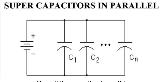
IV. SUPERCAPACITOR BANKS
The voltage rating of each supercapacitor is 2.7V per cell. The voltage level is derived from the electrochemical stability of electrolyte and electrode materials. Since the most applications require voltage more than 2.7V, multiple cells can be placed in series to fulfill the voltage requirement. Also depending on energy requirement these multiple cells can be placed in parallel.
Figure 2 Supercapacitors in parallel
[image:3.612.176.439.520.652.2]©IJRASET: All Rights are Reserved
812
[image:4.612.239.374.163.272.2]parallel will give a capacitance of 48F and a maximum system voltage of 3.7V. In Parallel connection of supercapacitor, if same value cells placed in parallel, they will decrease the overall system equivalent series resistance.
Figure 3 Supercapacitors in series
In series connection of supercapacitors, when the cells placed in series the system voltage is increased because the voltage gets added in series combination. This voltage is increased by the number of cells connected in series. For example, if 3 cells rated at 3.7V each connected in series will give maximum system voltage of 11.1V. In series connection of supercapacitor bank, when the cells of same value placed in series the capacitance is reduced by the number of cells placed in series. In series connection, if the same value cells placed in series the overall system equivalent series resistance will increased.
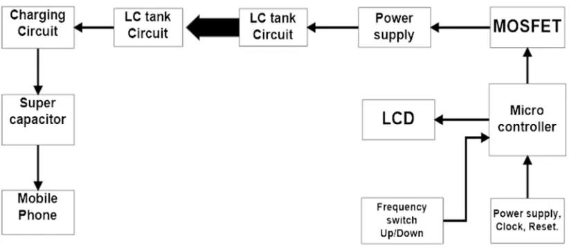
V. IMPLEMENTATION OF BATTERY-LESS PHONE
The block diagram consist of various blocks in the proposed system is shown in the Figure 4
Figure 4 Proposed block diagram
[image:4.612.112.523.444.626.2]©IJRASET: All Rights are Reserved
813
A. The Parts of Transmitter Section are1) Primary coil
2) Amplifier
3) Microcontroller
4) LCD display
Primary coil is having LC tank circuit and it generates resonance, the coil is made up of copper wire to reduce cost and to reduce losses and resistivity. Here we need to transfer 1A to 3A of current to the receiver. Therefore we use 16 gauge wires for transmitter coil. As the inductance is directly proportional to number of turns of the coil the selection of the number of turns is important. The use of electrolytic capacitors or polarized capacitors may damage the circuit; therefore we use the paper capacitors because they are safe and reduce risk of damage. Now we need to produce the oscillating frequency of 40 kHz. Here we use a digital oscillator to generate 40kHz of frequency, Analog oscillator is having a problem of frequency change because of change in temperature, therefore to set desired frequency we connect two push button switches to microcontroller Atmega16 and this frequency is displayed on 16*2 LCD display which is also connected to microcontroller, to control the brightness of a LCD display variable resistor is used. Microcontroller will produce a square wave of 5V and is having less current value which is not sufficient to charge the mobile phone. So we connect n-channel MOSFET (IRF 250) to microcontroller for transmission of large value of current, the output of microcontroller is amplified by MOSFET and then given to primary coil, here two separate power supply for LC tank circuit and microcontroller are used. Two step down transformer is use to convert voltage from 230V to 18V / 15V.
The receiver section is also having LC tank circuit having size similar to mobile phone; transmitter's LC tank circuit will transfer power to receiver's LC tank circuit wirelessly. It means wireless power transfer between primary and secondary coil takes place, but here power is in the form of AC supply, we need DC supply to charge mobile phone, so we connect bridge rectifier to LC tank circuit of receiver section to convert AC supply to DC supply, charging pad must transmit 18V so that receiver receives minimum 15V supply. To generate high voltage, the capacitor bank of supercapacitors is used. We need to connect super capacitors in a series and parallel manner. To protect capacitor bank from high voltage use voltage regulator and connect in between bank and rectifier. If the circuit is switched off, the capacitor gets discharged. So here use a diode in series with bank. The diode allows unidirectional supply towards capacitors and it also eliminates capacitors discharging problem. As we give small DC current to mobile phone, we need to use DC-DC converter in between supercapacitor bank and mobile phone to prevent damage of mobile phone.
VI. RESULTS
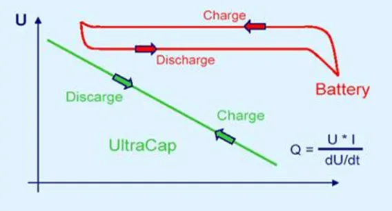
[image:5.612.163.447.526.679.2]The super capacitors are widely available from the range of 1F to 3000F. But it is difficult to find the exact value of capacitance equivalent to the battery. We have selected a supercapacitor of rating 4F and 5.5 volt. We used the combination of two supercapacitors in series with the four parallel branches each of two farad. The 8F super capacitor bank that we used gets full charged in 150-180 seconds. The Figure 5 shows the charging and discharging time of supercapacitor bank and the lithium ion battery. From the graph it can be visualize that how quickly the supercapacitor gets charged.
Figure 5 Charging and discharging time of SC bank
©IJRASET: All Rights are Reserved
814
[image:6.612.143.489.98.258.2]discharging time of mobile. The discharge of energy depends on the type of application running on the mobile.
Figure 6 discharge time of mobile
From the graph it can be seen that the mobile phone last for 35 min. when the phone is kept for an ideal condition. 12 minutes when the flash light in the mobile is running the mobile phone lasts for 12 mins. And it lasts for 14 minutes when the user plays games in the mobile phone.
VII. CONCLUSION
The supercapacitors gets charged quickly, it save a lot of time for charging the devices. It also avoids many hazardous things which a battery can be emits. The weight of supercapacitors is less and also it has longer life than batteries. The supercapacitors are expensive and bulky than batteries. The recent research shows that the cost of supercapacitors is decreasing and with the invention of newer technology the size of supercapacitors is also reduced day by day. In future supercapacitors will be used in many applications and one of the most important applications will be to charge mobile phones by replacing the conventional batteries.
REFERENCES
[1] J.Monteirp, N.Garrido, R.Fonseca, “An experimental study of an efficient supercapacitor stacking scheme to power mobile phones”.
[2] R.L. Boylestad, Introductory Circuit Analysis, 12th ed, Pearson, 2014.
[3] Héctor D. Abruña, Yasuyuki Kiya, "Batteries and the electrochemical capacitors", 2013
[4] J. G. Schindall, The Change of the Ultra-Capacitors, IEEE Spectrum, 2007.
[5] Adam Marcus Namisnyk, “ Survey of Electrochemical Supercapacitor Technology”, 2013.
[6] Raman. S.R “Review of charge equalization schemes for Li-ion battery and super-capacitor energy storage systems” IEEE Conference Publications ICAECC,
pp. 1 – 6 2014
0 10000 Ideal Flashlight Game 4000
1500 1800