Modeling and Control of Induction Motor using
Causal Informational Graph
S. Hassainia
R.Toufouti
S.Meziane
S.Kechida
Department of Electrical Engineering,SoukAhras,
University, Algeria
Department of Electrical Engineering, Souk Ahras
University, Algeria
Department of Electrical Engineering, Souk Ahras
University, Algeria
Department of Electrical Engineering, Guelma
University, Algeria
ABSTRACT
In this paper, we’d like to present a tool for modeling and representing systems that allows a subsequent structuring of their control o. This tool, which is the causal informational graph (CIG), allows to highlight the different relationships between energy variables in a system; supplemented by another tool that is the macroscopic energy representation (MER), which insists on the principle of action and reaction between the different elements of the system. These tools enable a dual interest, first developing the model for the system structure and its control. In this article we consider the application as electromechanical conversion chain with actuator as an induction machine.
Keywords
Causal Informational Graph (CIG), Inverse model of control, Induction machine, Field oriented control
1.
INTRODUCTION
Growing economic challenges require more effective and efficient systems. The electro-mechanical conversion is thus ensured by electrical systems increasingly complex: Heavy chain drive kinematics, multi -computer systems, multi-convertors systems .. Control of such systems is a challenging task because it must respond to the management of energy transformation that occurs through several interacting elements.
Various tools have been developed to have a representation of ordered action of energetic variables in a system; they aim at supporting the implementation of system control under study. Amongst these tools, the causal informational graph (CIG) [1] as graphical representation allows a synthetic description of the relationships between the variables of a process according to the notion of cause and effect, then the structure of control can be deduced by reversing the graph.
In this paper the principles of CIG will be subsequently applied to determine a control algorithm for induction machine . The control is addressed in a modular approach.
2.
CIG PROCESSORS
Processors are separate elements attached to an object or a set of localized objects within the studied process, they underpins a transformation relationship between one or more influencing magnitudes and an influenced magnitude; this relationship is induced by the principle of natural causality governing the energy operation of any object or group of objects [2] [8]. These transformational relations are of two types:
2.1. A Rigid Relationship
Bijective, reversible and independent of time, the input affects directly the output. The causality is external.
2.2. A Causal Relationship
Is characterized by a well-defined input and output, the cause and effect are interchangeable, and the relationship depends on time (a variation of the input implies an evolution of the output with a transient and steady state). The Causality is internal. Fig.1 gives symbolism to differentiate the two types of processors.
Fig.1: CIG representation of a processor
Natural causality for physical systems is integral causality: energy is a continuous function of time. Every physical entity may be represented by one or more connected processors.
3.
MODEL CONTROL
The ideal process control consists in the inversion of its main causality chain in order to define the control input depending on the desired output. Two types of inversion are defined: rigid relationships are directly inversed show Fig2.a; and the causal relationships which are reversed through an enslavement Fig.2b as their inputs and outputs are not interchangeable [3].
An enslavement relationship allows an indirect reversing of the non reversible relationship, but requires an additional input, ( the present output) in order to minimize the gap and ensure the further reference [10].
b) causal relationship
e(t) s(t)
a) rigid relationship
e(t) s(t)
a)Rigid Processus
e(t) s(t)
e_reg(t) s_ref(t)
b) causal Processus
e(t) s(t)
e_reg(t) s_ref(t) s_mes(t)
4.
ENEREGETIC MACROSCOPIC
REPRESENTATION
The energetic macroscopic representation is a condensed CIG whose graph is organized and simplified to make proof of the exchange variables of elements of an energetic conversion. A conversion of an electromagnetic chain relates an electric source ES to a mechanic source MC with:
An electrical convertor EC which adapts electrical power between the source and the machine;
An electrical machine EM which secures an electromagnetic conversion;
And a mechanic convertor MC which adapts the mechanic energy between the machine and the mechanic source.
Each of the conversion elements can dispose of a regulating vector . This representation proves the relationship of action and reaction between the different elements of the conversion chain, fig.3
Fig.3: The chain of electromagnetic conversion
In such chain, we can find that the accumulation elements are the elements that provide connection, the sources and the elements of conversion, the case of the windings of an electrical machine.
4.1 Control Structure Deduced From a
EMR
The CIG shows that the control of a process consists in the inversion of its model : find the right cause to generate the right effect [9] [11] ; this principle is applied to the EMR in order to deduce the control structure of an electromagnetic conversion chain.
(a)
(b)
4.2. Application
Fig.5: EMR of a conversion chain
4.2.1.
Sources definition
The electrical source imposes a continuous voltage Use, the mechanic source is assimilated to the load that the machine tows which imposes a resistant torque; we just need a constant resisting torque.
4.2.2.
Representation of a static converter
The static converter is a three phase inverter characterized by its modulation function mce with
Use
mce
Vc
Vb
Va
Uce
.
Where
3 1 2 1 1 1
.
2
1
1
1
2
1
1
1
2
3
/
1
f
f
f
mce
f11,f21 f31,constitutes the connection functions of the static
switchers of the inverter
4.2.3.
Representation of induction machine:The induction machine considered is classical, it is constituted of a stator, and rotor cage; the air gap is constant; the modeling is based on classical assumptions: unsaturated magnetic circuit, constant permeance and the notch effects are neglected [9], [11].
The equations of the induction machine are defined in the arbitrary Park referential. The voltage equations are:
d s rs q r q r
q r
q r rs d r d r
d r
d s s q s q s
q s
q s s d s d s
d s
dt
d
i
Rr
V
dt
d
i
Rr
V
dt
d
i
Rs
V
dt
d
i
Rs
V
.
.
0
.
.
0
.
.
.
.
(1)
Mechanical equations
Cr
C
f
dt
d
J
.
mcc
(2)ea_reg
Sa_ref Sa_mes er_mes
Sa er ea
Sr
I
eI
sC
rMC
EC
U
seU
sC
mccES
f_reg
EM
MS
Sa er ea
Sr
Sa_mes ea_mes ec_reg
EC
C-EC
Fig.4: control structure
EM
EC
MC
ES
MSUse Us Cmcc
Ie Is Cr
)
.
.
.(
dr qs qr dsem
i
i
Lr
M
C
(3)Flux equations
q s q r q r q r q s q s d s d r d r d r d s d si
M
i
Lr
i
M
i
Ls
i
M
i
Lr
i
M
i
Ls
.
.
.
.
.
.
.
.
(4) Autopilot equations
r
p
s
(5)Considering state variables statoric current and the rotoric flux, the calculations related to the modeling of induction machine in the Park referential linked to the turning field lead to the following expressions:
q r q r q r q r d r d r d r d r q s q s q s q s d s d s d s d se
dt
d
i
Rr
V
e
dt
d
i
Rr
V
e
dt
di
Ls
i
Rs
V
e
dt
di
Ls
i
Rs
V
.
0
.
0
.
.
.
(6)The ed and eq terms resulting from electromechanical and electromagnetic coupling between the windings similar to electromotive forces developed by a DC machine are defined as follows:
q s q r s q r d s q r s d r q r r r d s s d r q s q r q s s d r d si
Rr
Lr
M
p
e
i
Rr
Lr
M
p
e
L
MR
i
Ls
Lr
M
p
e
Lr
p
M
i
Ls
Lr
Rr
M
e
.
)
.
(
.
)
.
(
.
.
.
.
.
.
.
2 2
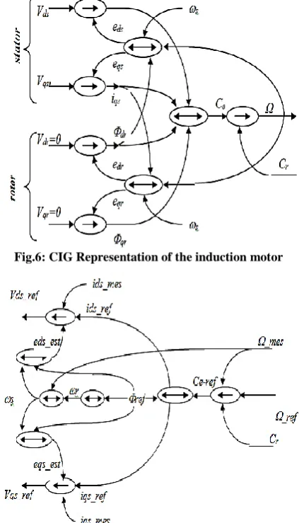
(7)Thus the induction machine model is illustrated by the CIG of figure .6.
4.3 Strategy of Control
To control the induction machine, it is necessary to decouple the flux control and the current generating the torque. To this end, we call on a control called vector control which directs
the flux on the axis of the Park referential by:
dr
r et0
qr .By using the voltage equations of the rotor, we will come to:
q s d r r d r d r d si
Lr
MRr
dt
d
Rr
Lr
i
M
.
.
.
(8)And the torque is
qs dr em
i
Lr
M
p
C
.
.
.
(9)From these equations, two magnitudes are to be controlled the flux and its position.
The flux is controlled by the current ids hence Vds, the torque is controlled by the current iqs hence Vqs
For an indirect control, we impose:
dr
ref
cste
[image:3.595.116.281.303.430.2]In respect to the rules of inversion of the CIG, we get to the control of the CIG fig.7 with speed correctors and current correctors. To choose the correctors, we can introduce the conventional corrector PI ou IP or smart correctors.
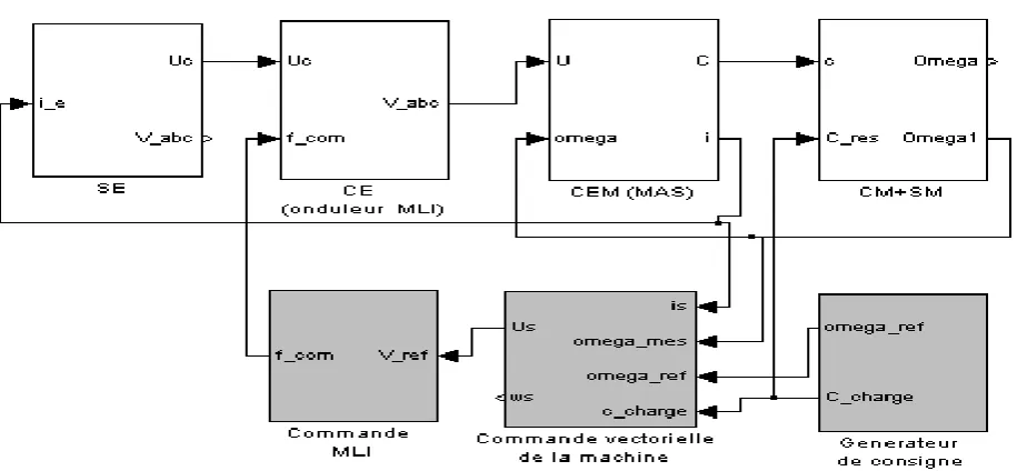
[image:3.595.323.535.369.739.2]Figure .8 illustrates the EMR of the conversion chain with the control axis brought out through Matlab Simulink.
Fig.6: CIG Representation of the induction motor
[image:3.595.65.279.495.624.2]
4.4 Results of Simulation
[image:4.595.318.537.359.661.2]Fig 8: Structuring Control of an Induction Machine
Fig.9a. Reference and rotor speed
Fig.9c. Direct and quatrature stator current
Fig.9b. Load and electromagnetic torques
Fig.9d. Reference and rotor flux
The simulation results on the figures 9 (a-d) shows that a good tracking performance is achieved and the above results demonstrate that the proposed controller has strong robustness properties in the presence of load disturbance and parameter variations. Consequently, the use of the proposed cascade predictive nonlinear control scheme can solve the control problem of induction machines in the presence of load torque variation.
From these results, as it may be observed, the rotor speed tracks the desired speed in spite of system uncertainties. Moreover, the speed tracking is not affected by the load torque change (figures 9.a) since the electromagnetic and load torque quickly recovers the applied load torque value (figures9b).
0 0.5 1 1.5
-400 -200 0 200 400
0 0.5 1 1.5
-4 -2 0 2 4
Cr Cem omega ref omega
0
0.5
1
1.5
-50
0
50
100
temps
id
sq
s
0.1
0.2
0.3
0.4
f
lu
x
iqs
ids
phi
r
phi__ref
0
0.5
1
1.5
-400
-200
0
200
400
0
0.5
1
1.5
-4
-2
0
2
4
Cr
Cem
omega ref
omega
0 0.5 1 1.5
-50 0 50 100
temps
id
sq
s
0 0.5 1 1.5
0 0.1 0.2 0.3 0.4
temps
f
lu
x
iqs ids
phir
[image:4.595.57.280.359.653.2]38 As the figure shows, the response of the flux is very good
because the real and estimated rotor flux tracks the reference values adequately (figures 7a and 7b). That figure shows the satisfying induction motor functionning; the rotor flux is maintained independently of the electromagnetic torque.
5. CONCLUSION
In this paper, we have presented a control structuring method of an electromagnetic conversion chain. The choice of the electromagnetic conversion chain concerning a chain with an induction machine is to make proof of the usefulness of formalism CIG and its importance for structuring of electrical machine control laws and complex systems.
This formalism (CIG) helps functional comprehension and description of the induction machine and allows the formulation of the machine control strategy by use of a simple logical reasoning that dwells in the step by step inversion of causalities.
Such a tool turns to be of great usefulness in the complex systems: the complex inversion chains (multi- machines, multi-convertors).
6. REFERENCES
[1] S.Hassainia , H Abbassi , S.Kechida’’
“
Structuration de la commande pour une chaîne de conversion électromécanique à courant alternatif”
3rd International Conference : Science of Electronic, Technologies of Information and Telecommunication. SETIT’2005, March 27-302005,Tunisia.[2] J. P Hautier , J. P Caron’’ Convertisseurs Statiques Méthodologie Causale de Modélisation et de Commande Ed Technique ’’, Paris 1999.
[3] P.J. Barre, J.P. Hautier, X. Guillaud and B.Lemaire-Semail, "Modelling and axis control of machine tool forhigh speed machining," in Proc. of the IFAC-IFIPIMACSConference (CIS’97), Belfort, France, 1997. [4] A.Bouscayrol, X Guillaud, P.Delarue, J.P.Hautier ’’
Structure de Commande d’un Processus Mono Machine’’, Séminaire SMM GDR SDSE Toulouse 18- 19 Novembre 1999.
[5] A.Bouscayrol, T . Communal ’’ Approche Globale De La Commande Dynamique de Machine Electrique’’ : Revue 3ei N°.17, Juin 1999 Pp73 -79
[6] S.HASSAINIA, H.ABBASSI and S.KECHIDA, «The structuring of electro mechanic conversion drive chain» International Journal of soft Computing, Vol N°1 (3),pp:155-159, 2006.
[7] Joseph Pierquin’’ Contribution à la Commande des Systèmes Multi Machine Multi - Convertisseurs Application à la Résolution De Problèmes En Traction Electrique’’.Thèse Présentée, De Doctorat de Université Lille Juillet 2002.
[8] Jia ZENG, Pierre-Jean BARRE, Philippe Degorert, “Modeling and Thrust Control of PMLSM Using Principle of Local Energy”, IEEE Conference Publications2003, Sixth International Conference on Electrical Machines and Systems, Beijing, China,ICEMS 2003, 9-11 Nov, Vol N°:1 , pp: 26 - 30.
[9] Ling Peng , Yongdong Li and Bruno Francois, “Modeling and Control of Doubly Fed Induction Generator Wind Turbines by Using Causal Ordering Graph during Voltage Dips” , IEEE Conference Publications 2008, International Conference on Electrical Machines and Systems, Wuhan, 17-20 Oct. 2008, Page(s): 2412 – 2417, ICEMS 2008.
[10]K. Hartani, Y. Miloud, A. Miloudi, “Méthodologie Causal de modélisation et de commande : application aux machines électriques’’, CIIA-2009, Conférence Internationale sur l'Informatique et ses Applications, Proceedings of the 2nd Conférence Internationale sur l'informatique et ses Applications (CIIA'09) , Saida, Algeria, May 3-4, 2009.
[11]Yvan Crévits, Xavier Kestelyn, Betty Lemaire-Semail, Éric Semail, " Modélisation causale pour la commande auto adaptée de machines alternatives triphasées en mode dégradé ", Manuscrit auteur, publié dans European Journal of Electrical Engineering (EJEE), 13, 6 (2010),pp 345-384