Design and Performance Analysis of Asynchronous
GRO based Time to Digital Converter
Anita Arvind Deshmukh
VNIT, S.A. Road, Nagpur, Maharashtra,India
Akash Joshi
VNIT, S.A. Road, Nagpur, Maharashtra,India
R. B. Deshmukh
VNIT, S.A. Road, Nagpur, Maharashtra, India
ABSTRACT
An Asynchronous Gated Ring Oscillator based Time to Digital Converter (A-GRO-TDC) is proposed. Gating functionality is added to a simple Ring Oscillator which drastically improves the system performance with asynchronous operation. Energy saving is possible due to scrambling and first order noise shaping. The proposed 9 bit A-GRO-TDC is implemented in Cadence using 0.18µm digital CMOS Technology. Pre and post layout simulation with corner analysis shows good linearity. All these features with very little power between 16µW to 26µW make it suitable for IoT applications. It consumes an active area of 550µm x 410µm. .
General Terms
Data Communication, Internet of Things (IoT), Signal Processing, Asynchronous.
Keywords
Gated Ring Oscillator (GRO), Time To Digital Converter (TDC), Quantization Noise Shaping, Scrambling, Delay Stages.
1.
INTRODUCTION
Currently wireless high speed digital data communications is preferable for Internet of Things (IoT) with minimum energy consumption as the determining design factor. Low energy consumption throughout the whole device is crucial to enhance its autonomy, allowing to use its large arsenal of complex functions and applications without draining the battery too much. One crucial element in the data communication is the Analog-to-Digital Converter (ADC), converting the real-life electric signals through the air to the original digital message [1].
With technology scaling to deep-submicron, analog design becomes critical due to reduced power supply. It needs more efforts to integrate in a noisy environment as the noise adversely affects the gain and signal swing. Also noise and mismatch problems become more serious. Comparatively digital circuits scale splendidly with technology, providing numerous advantages like: improved performance with high speed, very less power consumption, minimum area and high packing density etc. With these advantages of scaling, promising digital TDC implementation is preferable for ADC. In time based digital approach, the resolution is no longer dependent on the sampling clock but depends on the propagation of a delay gate which lowers with technology scaling. So Time to Digital Converter (TDC) is the reliable design.
[image:1.595.337.519.180.268.2]Recently, TDC has also become the major block for various time measuring VLSI implementations like Digital Phase
Fig 1: Block diagram of DPLL [2]
Locked Loop (DPLL) as shown in Fig. 1. Design of Phase Lock Loop (PLL) turn out to be increasingly difficult with the scaling, due to large loop filter capacitors. This problem can be conquered by using DPLL which uses a digital filter. TDC and the divider output [3]. Overall TDC proved to be an important block in various implementations required for digital data communications for Internet of Things (IoT).
So here we propose the implementation with performance analysis of a Time to Digital Converter which uses Asynchronous Gated Ring Oscillator (A-GRO). The performance metrics of this design are: high linearity in time to digital mapping characteristics, low power and noise shaping. Ring Oscillator (GRO) provides noise shaping at the output of TDC. Asynchronous implementation supports for minimum power consumption as it consumes power only during the data arrival. Hence it can be effectively used for ultra low power interfaces getting popular with IoT applications.
Rest of the paper is structured as follows. In section 2 backgrounds is discussed. Section 3 explains TDC Fundamentals. Asynchronous GRO-TDC operation is explained in section 4. Section 5 proposes A-GRO-TDC implementation. Results are in presented section 6. Paper is concluded in section 7.
2.
BACKGROUND
Various TDC designs have been proposed till today with its pros and cons. Few of the designs are summarized here. Antti Mäntyniemi et al. presented an integrated 9-channel parallel TDC for a 3D imaging pulsed time-of-flight laser range-finder Since the start and stop pulses are asynchronous with respect to the reference clock, the risk of metastability is always present when trying to synchronize the input pulses to the reference clock using flip-flops. However, synchronizing is necessary in order to be able to start the counter clock signal with the start pulse and to be able to catch the counter state with the stop pulses. At the same time, the state of the delay line stored with the asynchronous start and stop pulses must be consistent with the corresponding counter state. A double synchronizing scheme where the start and stop signals are synchronized to both rising and falling edge of the reference clock is used [4].
pulses. Since the measurement is asynchronous with respect to the system clock, averaging can be used to improve resolution. To improve the single-shot resolution the non-synchronous parts are digitized separately with interpolators. Thus, the measurement range is set by the number of bits in the counter and limited only by the stability of the system clock [5].
Belal M. Helal et al. proposed the ring oscillator based TDC that is gated on and off to accurately measure time and scramble the measurement's residual error [6]. Thus first order noise shaping is possible. So we preferred this simple TDC architecture based on digital delay line as it also provides better linearity and hence the improved resolution.
3.
TDC FUNDAMENTALS
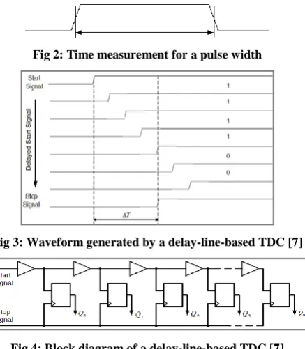
TDC basically measures time information of one or more discrete amplitude signals and provides digital representation for further signal processing. Depending on the application, time information can either be the time difference between the rising edge of a start and a stop signal (pulse width) or the location of the edges relative to the a reference signal. For IoT, proposed TDC measures a pulse width as shown in Fig. 2.
Till now various TDC architectures have been proposed like based on digital counters, digital delay line etc. In counter based TDC, the measurement time intervals are not synchronous to the reference clock, which introduces error to the obtained result. The quantization resolution is dominated by the reference clock period. However, it is not effective to increase the clock frequency for higher TDC resolution. Not only does the higher clock frequency consume more power, but also the counter has a timing restriction [7].
[image:2.595.317.541.465.589.2]Digital delay-line-based TDC uses a chain of digital delay elements to quantize the time interval instead of reference clock. This kind of architecture improves the resolution to the delay of the delay elements in the chain. The operation principle of delay-line-based TDC is illustrated in Fig. 3.
Fig 2: Time measurement for a pulse width
[image:2.595.315.539.466.726.2]Fig 3: Waveform generated by a delay-line-based TDC [7]
Fig 4: Block diagram of a delay-line-based TDC [7]
The start and stop signals indicate the time interval being measured. As the start signal delayed by a chain of delay elements, the stop signal will be in phase with the Nth -stage delayed start signal. Flip-flops as a sampling block detect the
point at which the stop signal and delayed start signal synchronizes. The delay that causes the two signals in phase reflects the measurement time interval. The core structure of delay-line-based TDC is shown in Fig. 4. The start signal propagates along a delay chain, and each delayed start signal is clocked by the stop signal in the sampling flip-flops. When the stop signal samples the delayed start signals at rising edge, the delay stages that have been already passed by the start signal generate "1" at flip-flops‟ outputs and the delay stages that have not been passed by the start signal yield "0" outputs.
The transition point of "1" to "0" indicates that the start signal and the stop signal are in parallel with each other at this point. Compared to the resolution of a counter-based TDC, the resolution of delay line- based TDC does not rely on a high frequency reference clock, but on the delay of each delay element. This architecture improves the resolution to a gate delay, while it consumes not much power.
Typically, the resolution of a TDC is determined by the gate delay of the process used, but some techniques have been adopted to improve the resolution, such as the Vernier TDC, the pulse shrinking TDC, and the gated-ring oscillator (GRO) based TDC [8]. We preferred the GRO-TDC, since with the first-order noise shaping effect, the quantization noise is moved to high frequency, thus a lower in-band noise is achieved and a better effective resolution is obtained. Moreover we propose the clockless Asynchronous GRO-TDC for IoT data communication, as it avoids clock related issues like jitter, supplementary implementation and added power consumption.
4.
ASYNCHRONOUS GRO-TDC
OPERATION
Fig. 5 a) illustrates the key concept of the GRO-TDC operation. This GRO is different from traditional ring oscillator as it is gated by the transistor switches in series with the positive and negative power supply to individual inverter
Fig 5: a) GRO –TDC implementation b) GRO Delay stage [9]
[image:2.595.61.280.467.718.2]as in Fig. 5 b). Gating circuitry for oscillator consists of nMOS and pMOS enable devices. This is to hold the state of the oscillator between measurements. So the ring oscillator stopping phase of the given measurement interval correspond to starting phase of a next measurement interval.
During a specified measurement, GRO structure is „Gated ON‟ or „Enabled‟ (EN in Fig. 5 b)). So GRO starts oscillating, simply oscillation is enabled with the closed switches and the GRO behaves identically to a classical ring oscillator. Conversely, with the open switches, i.e. „Gated OFF‟ or „Disabled‟ (ENB in Fig. 5 b), the inverter delay element is unable to charge or discharge the output parasitic capacitors, and hence oscillation is suspended. So at the end of the enabled state, oscillator phase is then detained. Thus throughout the disabled state, the charge remains stored on the parasitic capacitors of the delay elements till the next measurement cycle begins as shown in Fig. 6. Thus the first order quantization noise shaping benefits in power saving compared to the free running oscillator based TDC [2]. It leads to increases in the effective resolution of GRO-TDC by reducing the in-band quantization noise.
The overall quantization noise is the difference between the current quantization noise and the previous quantization noise.
𝑇𝑒𝑟𝑟𝑜𝑟 𝑘 = 𝑇𝑠𝑡𝑜𝑝 𝑘 − 𝑇𝑠𝑡𝑎𝑟𝑡 𝑘
= 𝑇𝑠𝑡𝑜𝑝 𝑘 − 𝑇𝑠𝑡𝑜𝑝 𝑘 − 1 (1)
Obviously first order quantization noise shaping is also achieved at the GRO-TDC output. Thus GRO-TDC quantization noise is pushed out of band. Along with this the GRO-TDC also reveals significant characteristic of first-order shaping for the delay element mismatch due to the barrel shifting through the delay stages. Similar to the transfer of quantization error, the mismatch errors for one sample are also passed onto and subtracted from the next sample. This is due to the variable starting phase of the oscillator at the beginning of different measurement intervals. Such a scrambling allows improvement in resolution of the signal through averaging of the GRO measurements [2]
In summary, the GRO - TDC can achieve scrambling of its quantization and mismatch error, as well as first-order noise shaping. These advantages result in the fact that no calibration needs to be performed of the TDC to achieve high resolution and linearity, even in cases of large mismatch [2].
Function of the counter is to count the number of edges (positive or negative) happening during each period of the ring oscillator through a measurement interval. Adder adds the final counts and saves in a register. The proposed design is the improved implementation as compared to shown in Fig. 5 a) which is discussed in further section.
5.
PROPOSED ASYNCHRONOUS
GRO-TDC
The proposed improved design avoids the use of SR-FF. Instead we designed it to enable the gating of ring oscillator with the rising edge of timing signal. GRO remains on till the complete measuring cycle. As soon as the falling edge arrives, gating disables the ring oscillator. These rising and falling timing signals, starts and stops the counters and the registers. Delay element is added before the enable/disable signal to registers; to compensate for the delay from the disable to counter output. Otherwise disable signal may stop the registers before saving the last count propagation. So there is no adding up mislaid problem.
Thus the proposed implementation operates asynchronously, i.e. GRO starts/stops depending on rising/falling edge of the measuring time signal. Here the clock signal is completely avoided which further saves power and area. Since it is processing the signal only during when data arrives, it can be defined as an Asynchronous GRO-TDC (A-GRO-TDC).
5.1
A-GRO-TDC Implementation
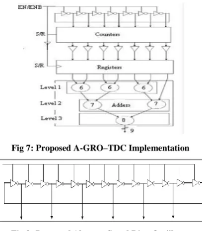
[image:3.595.327.531.459.692.2]The block diagram of the proposed A-GRO-TDC is shown in Fig. 7. The timing signal pulse width which is to be measured is applied to “EN” pin of the A-GRO-TDC. This pulse width to be detected must have two clearly distinct voltage levels, low and high (i.e. 0 and 1). Rise time when the pulse width takes the high or 1 state, enables the system which is the start of a measurement interval. At the same time gating functionality turns „ON‟ the ring oscillator. Frequency of oscillation is given by;
𝑓𝑂𝑆𝐶= (2𝑁𝑡𝑃𝐷)−1 (2)
where,
𝑓𝑂𝑆𝐶 frequency of oscillation of the gated ring oscillator
𝑁 number of delay elements using in the ring oscillator
𝑡𝑃𝐷 propagation delay of delay element
The phase of this waveform decides resolution of the proposed A-GRO-TDC. At the end of measurement interval, low or 0 state disables the GRO and it stops oscillating. GRO further hold its phase till the beginning of the next measurement interval. Thus the first order quantization noise shaping is achieved which leads to energy saving.
GRO is designed for minimum number of stages to achieve, minimum area and low power consumption. Proposed GRO is implemented with minimum delay which required 13 delay stages as shown in Fig. 8. Out of 13 stages outputs are taken from the alternate delay stages i.e. only 7 outputs are further
[image:3.595.347.515.463.592.2]Fig 7: Proposed A-GRO–TDC Implementation
Fig 8: Proposed 13 stage Gated Ring Oscillator
at the output of counter differs. 6 bit asynchronous up counter is employed which is connected to each output of the ring oscillator.
Counter output is fed to the 6 bit registers through buffers which will latch the contents at the output of counter before it is cleared between the successive measurement intervals. The output of each of 6 bit register is then added by the adder block. Proposed adder blocks consist of three levels as shown in Fig. 7. Level 1 uses three 6 bit adders and one carry bit. So it provides 7 bit output which is further processed by Level 2 having two 7 bit adders. Output is finally supplied to 8 bit adder which is Level 3. At the end it provides an output which is 9 bits wide. Simply A-GRO-TDC converts time to digital signal which can be a major block of digital data communication for IoT.
Proposed A-GRO-TDC is implemented in Cadence with 0.18µm digital CMOS technology.
6.
RESULTS AND DISCUSSION
Performance has been verified for the proposed implementation through various simulations. The proposed 13 stage GRO oscillates at 285.7 kHz. The Fig. 9 shows how the GRO holds its phase between two measurement intervals. It can be clearly observed that GRO is disabled (no oscillations) between two measurement intervals and holds its phase from end of one measurement interval to the beginning of next measurement interval. Thus the first order quantization noise shaping is possible at the output. The ring oscillator is designed to work at a frequency range of 5 kHz to 15 kHz.
[image:4.595.316.535.71.226.2]First we verified the transfer characteristic of A-GRO-TDC i.e. digital output code vs. pulse width to be measured Fig. 10 represents transfer characteristic output with 5 KHz input and pulse width varying from 20µs to 180µs. Similarly Fig. 11 shows the transfer characteristics with 15 kHz input and pulse width varying from 6.5µs to 58.5µs.
Fig 9: GRO holds its phase during measurement interval
Fig 10: A- GRO-TDC output against pulse width at 5 kHz
Fig 11: A-GRO-TDC output against pulse width at 15 kHz
Fig. 10 and Fig. 11 conclude that proposed design achieves good linearity over the entire measurement range.
[image:4.595.316.543.374.740.2]Subsequently, we calculated the power dissipation. Fig. 12 indicates the power dissipated by the proposed implementation. It is measured at maximum 15 KHz input with the pulse width varying from 6.5µs to 58.5µs with step size of 6.5µs. Fig. 12 indicates very less power consumption i.e. between 16µW to 26µW. Average current consumption ranges from 9µA to 14.7µA from a 1.8V supply. Compared to [9] and [10], the proposed A-GRO-TDC is simple and consumes very less power.
[image:4.595.57.281.460.571.2]Fig 12: Power consumed by Proposed A-GRO-TDC
Fig 13: Layout of A-GRO-TDC
[image:4.595.56.278.588.743.2]layout simulations are performed and compared to pre layout simulations. Comparison for transfer characteristics are presented in Fig. 14 and Fig. 15 for 5 KHz and 15 KHz inputs respectively. It can be observed that the pre layout and post layout simulation results deviate negligibly due to the interconnect parasitics considered during post layout simulations. Overall the Linearity is still maintained over the entire measurement interval.
[image:5.595.316.541.139.497.2]To verify the noise shaping at output of A-GRO–TDC, 8192 point FFT is obtained. Periodic input with varying pulse width is needed. It is very difficult to obtain an input whose pulse
[image:5.595.56.279.199.345.2]Fig 14: Pre Layout vs. Post Layout Simulation at 5 kHz
Fig 15: Pre Layout vs. Post Layout Simulation at 15 KHz
Fig 16: 8192 Point FFT for Proposed A-GRO-TDC
width spans the entire measurement range of the A-GRO-TDC. We preferred average frequency i.e. 10 KHz. As per calculations for 8192 points it shows 9.68 KHz. So duty cycle modulated input with 9.68 KHz is applied. Fig. 16 shows the obtained FFT spectrum. Quantization noise shaping is clearly visible.
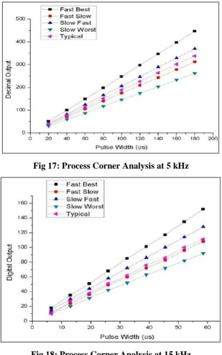
[image:5.595.56.278.363.514.2]Fig 17: Process Corner Analysis at 5 kHz
Fig 18: Process Corner Analysis at 15 kHz
Additionally process corner analysis is also completed. Fig. 17 and Fig. 18 demonstrate the transfer characteristic post layout simulations against various process corners at 5 KHz and 15 KHz inputs respectively. The best results are obtained for “Fast_Best” corner and worst result for the “Slow_Worst” corner. It can be concluded that the linearity is maintained over all the process corners.
7.
CONCLUSION
The proposed A-GRO-TDC is successfully implemented in 0.18µm digital CMOS technology with minimum area and very little power requirement due to first order noise shaping. As it shows good linearity over the measurement interval the implementations is reliable for Time-To-Digital Conversion. Energy saving is possible due to asynchronous operation and hence useful for data communication in various IoT applications without draining the battery.
8.
ACKNOWLEDGMENTS
[image:5.595.54.281.535.738.2]9.
REFERENCES
[1] Jorg Daniels, “Time-Based Analog-to-Digital Converters for Broadband Communication Applications”, Katholieke Universiteit Leuven, PhD dissertation report, 2011.
[2] Matthew Z. Straayer and Michael H. Perrott, “A Multi- Path Gated Ring Oscillator TDC With First-Order Noise Shaping,” IEEE Journal of Solid-State Circuits, vol. 44, No.4, April 2009, pp. 1089-1098.
[3] C.-M. Hsu, M. Straayer, and M. H. Perrott, “A low-noise wide-BW 3.6 GHz digital ΔΣ fractional-N frequency synthesizer with a noise shaping time-to-digital converter and quantization noise cancellation,” IEEE Journal of Solid-State Circuits, Dec.2008, vol.43, no.12, pp.2776-2786.
[4] A. Mantyniemi, T. Rahkonen, and J. Kostamovaara, “A 9-channel time to digital converter for an imaging lidar application”, 23rd
European Solid State Circuits Conference ESSCIRC‟97, 16-18 Sept.1997, pp. 232– 235.
[5] Elvi Räisänen-Ruotsalainen, Timo Rahkonen, Juha Kostamovaara, “A High Resolution Time-to-Digital Converter Based on Time-to-Voltage Interpolation,” 23rd European Solid State Circuits Conference, ESSCIRC‟97, 16-18 Sept.1997, pp.332-335.
[6] B. Helal, M. Straayer, and M. H. Perrott, “A low jitter 1.6 GHz multiplying DLL utilizing a scrambling time-to-digital converter and time-to-digital correlation,” in VLSI Symp. Dig. Tech. Papers, Jun. 2007, pp. 166–167.
[7] Ji Wang. Modeling And Implementation of All-Digital Phase-Locked Loop Based on Vernier Gated Ring Oscillator Time-to-Digital Converter. Master‟s Thesis. Department of Electrical and Information Technology, Faculty of Engineering, LTH, Lund University, October 2014.
[8] Jiang Chen; Huang Yumei and Hong Zhiliang, “A multi-path gated ring oscillator based time-to-digital converter in 65 nm CMOS technology” Journal of Semiconductors, Vol. 34, No. 3. March 2013, pp. 035004-1 to 035004-5.
[9] Helal, B.M.; Straayer, M.Z.; Gu-Yeon Wei; Perrott, M.H., "A Highly Digital MDLL-Based Clock Multiplier That Leverages a Self-Scrambling Time-to-Digital Converter to Achieve Subpicosecond Jitter Performance," IEEE Journal of Solid-State Circuits, April 2008, vol.43, no.4, pp.855,863,.
![Fig 1: Block diagram of DPLL [2]](https://thumb-us.123doks.com/thumbv2/123dok_us/8023081.766667/1.595.337.519.180.268/fig-block-diagram-of-dpll.webp)