International Journal of Emerging Technology and Advanced Engineering
Website: www.ijetae.com (ISSN 2250-2459,ISO 9001:2008 Certified Journal, Volume 3, Issue 12, December 2013)
217
Analysis of the Effect of Tap Changing Transformer on
Performance of SVC
Dipesh A. Patel
1, Nirav P. Patani
2, Prabhat Kumar
31
Senior Lecturer, Electrical Engineering Department, M.L.I.D.S. Bhandu, Gujarat.
2M.Tech. Student EED, Arya college of Engineering & IT, Kukas Jaipur.
3 Professor, Department of Electrical Engineering,Arya college of Engineering& IT, Kukas Jaipur
Abstract— Most of the worlds electric power supply
systems are widely connected, involving connections inside utilities of own territories which extend to inter-utility interconnections and then to inter-regional and international connections. This is done for economic reasons, to reduce the cost of electricity and to improve reliability of power supply. Worldwide transmission systems are undergoing continuous changes and restructuring due to steady growth in demand for electric power, much of which has to be transmitted over long distances. Moreover, in today’s scenario power systems are more difficult to operate, the reason behind this is deregulation issues which requires an open access power delivery system which enables power delivery within and between the regions, facilitates access to interconnected competitive generation, little or no market based incentives for transmission investment & the other reliability, security and stability issues. These trends have led to extensive research interest in flexible ac transmission systems (FACTS), with the aim of developing new devices and technologies to control the flow of power, so as to allow more efficient usage of existing power generation and transmission power plants. The focus of this research work is on the application of Static VAR Compensator with tap-changing transformer to solve voltage regulation and power transfer capabilities.
Keywords— FACTS; Voltage stability; SVC; OLTC; PV curve
I. INTRODUCTION
The recent studies reveal that FACTS controllers could be employed to enhance power system stability in addition to their main function of power flow control. The literature shows an increasing interest in this subject for the last two decades, where the enhancement of system stability using FACTS controllers has been extensively investigated SVC is a mature thyristor based controller that provides rapid voltage control to support electric power transmission voltages during and immediately after major system disturbances.
Several studies have shown that transformer with automatic tap-changing can be used for improvement of voltage stabilities [4, 5], for both steady state and transient voltage stabilities.
Some of these studies were interested in proposing new models of tap-changing transformers. On the other hand, Static VAR compensator is used for improvement of voltage stabilities [6,7,8] due to line opening in the presence of induction motor or due to starting of induction motor or due to recoveries of short-circuit at induction motor terminals or due to heavy load abilities. With this static VAR compensator we can also use the series capacitor [9].The combination of the static VAR compensator and tap-changing transformer is suggested in [10].
Hiroshi Ohtsuki, Akihiko Yokoyama, Yasuji Sekine, presented the work on Reverse action of on-load tap-changer in association with voltage collapse [4]. They discuss the reverse action that the secondary voltage of a transformer is pulled down when the tap position of on-load tap changer is raised to increase the secondary voltage.
S. Milan, Calovic, presented the work on Modeling and analysis of under load tap-changing transformer control systems [5]. Here a nonlinear system model is derived, suitable for analysis of voltage and reactive power flow control applications of ULTC transformers in the consideration of mid-term and long-term dynamics and steady-state behavior of power systems.
International Journal of Emerging Technology and Advanced Engineering
Website: www.ijetae.com (ISSN 2250-2459,ISO 9001:2008 Certified Journal, Volume 3, Issue 12, December 2013)
218
M.Z. El-Sadek, et al, presented the work on Series capacitor combined with static VAR compensator for enhancement of steady-state voltage stability [9].They discussed the nonlinear dynamic controller for a combination of static series capacitor compensation and power system stabilizer, for enhancement of both voltage and transient stability of power system. The proposed controller implements speed deviation signal and generator terminal current deviation signal. The proposed Scheme is validated using a sample single machine infinite bus power system loaded by a frequency dependent voltage dependent nonlinear dynamic load type.
II. VOLTAGE STABILITY
Power system stability is defined as a characteristic for a power system to remain in a state of equilibrium at normal operating conditions and to restore an acceptable state of equilibrium after a disturbance. Traditionally, the stability problem has been the rotor angle stability, i.e. maintaining synchronous operation. Instability may also occur without loss of synchronism, in which case the concern is the control and stability of voltage.
The voltage stability is the ability of a power system to maintain steady acceptable voltages at all buses in the system at normal operating conditions and after being subjected to a disturbance.‖
Power system is voltage stable if voltages after a disturbance are close to voltages at normal operating condition. A power system becomes unstable when voltages uncontrollably decrease due to outage of equipment (generator, line, transformer, bus bar, etc.), increment of load, decrement of production and/or weakening of voltage control. According to reference the definition of voltage instability is ―Voltage instability stems from the attempt of load dynamics to restore power consumption beyond the capability of the combined transmission and generation system.‖ Voltage control and instability are local problems. However, the consequences of voltage instability may have a widespread impact. Voltage collapse is the catastrophic result of a sequence of events leading to a low-voltage profile suddenly in a major part of the power system.
Voltage stability can also be called ―load stability‖. A power system lacks the capability to transfer an infinite amount of electrical power to the loads. The main factor causing voltage instability is the inability of the power system to meet the demands for reactive power in the heavily stressed systems to keep desired voltages.
Other factors contributing to voltage stability are the generator reactive power limits, the load characteristics, the characteristics of the reactive power compensation devices and the action of the voltage control devices. The reactive characteristics of AC transmission lines, transformers and loads restrict the maximum of power system transfers. The power system lacks the capability to transfer power over long distances or through high reactance due to the requirement of a large amount of reactive power at some critical value of power or distance. Transfer of reactive power is difficult due to extremely high reactive power losses, which is why the reactive power required for voltage control is produced and Consumed at the control area.
Power system stability is classified above as rotor angle and voltage stability. A classification of power system stability based on time scale and driving force criteria is presented in Table I. The driving forces for an instability mechanism are named generator-driven and load-driven. It should be noted that these terms do not exclude the effect of other components to the mechanism. The time scale is divided into short and long-term time scales.
TABLE- I
CLASIFICATION OF POWER SYSTEM STABILITY
International Journal of Emerging Technology and Advanced Engineering
Website: www.ijetae.com (ISSN 2250-2459,ISO 9001:2008 Certified Journal, Volume 3, Issue 12, December 2013)
219
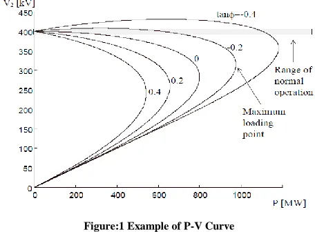
[image:3.612.53.281.249.417.2]The voltage dependence of loads affects the point of voltage collapse. The power system becomes voltage unstable at the voltage collapse point. Voltages decrease rapidly due to the requirement for an infinite amount of reactive power. The lower part of the PV-curve (to the left of the voltage collapse point) is statically stable, but dynamically unstable. The power system can only operate in stable equilibrium so that the system dynamics act to restore the state to equilibrium when it is perturbed.
Figure:1 Example of P-V Curve
Figure 1.2 presents five PV-curves for the test system (V1=400 kV and X =100 Ω). These curves represent
different load compensation cases (tan¢=Q/P). The load compensation makes it possible to increase the loading of the power system according to voltage stability.
The automatic voltage control of power transformers is arranged with on-load tap changers. The action of tap changer affects the voltage dependence of load seen from the transmission network. Typically a transformer equipped with an on-load tap changer feeds the distribution network and maintains constant secondary voltage. When voltage decreases in the distribution system, the load also decreases. The tap changer operates after time delay if voltage error is large enough restoring the load.
Facts Controllers For Power System
FACTS Controller is ―A power electronic based system and other static equipment that provide control of one or more AC transmission system parameters.‖
In general FACTS controllers can be divided in to three categories:
1. shunt connected controllers 2. series connected controllers
3. combined shunt & series connected controllers Key benefits of applying FACTS to eliminate transmission constraints:
1. Voltage stability
2. Increased loading and more effective use of transmission corridors
3. Added power flow control 4. Increased system security 5. Increased system reliability
6. Added flexibility in sitting new generation
7. Elimination or deferral of the need for new transmission lines
A shunt connected static VAR generator or absorber whose output is adjusted to exchange capacitive or inductive current so as to maintain or control specific parameters of the electrical power system (typically bus bar voltage). This is the general term used for a thyristor-controlled or thyristor-switched reactor or thyristor-switched capacitor or combination. SVC is based on thyristor without the gate turn off capability.
By placing the shunt compensator in the middle of a line and therefore dividing the line into two segments, the voltage at this point can be controlled such that it has the same value as the end line voltages. This has the advantage that the maximal power transmission is increased. If the shunt compensator is located in the end of a line in parallel to a load it is possible to regulate the voltage at this end and therefore to prevent voltage instability caused by load variations or generation or line outages.
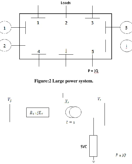
III. INTRODUCTION ABOUT SYSTEM UNDER STUDY
A large Power System which feeds a certain load or power (P+jQ) is used in this study as shown in Fig. 3.1. The system, at steady-state conditions can be represented by its Thevenin‘s equivalent seen from node 5 as shown in fig. 3.2. The tap-changing transformer is connected at the load terminal, its off-nominal tap ratio is‗t‘. Transformer reactance at unity off-nominal tap ratio is Xt.. All the
International Journal of Emerging Technology and Advanced Engineering
Website: www.ijetae.com (ISSN 2250-2459,ISO 9001:2008 Certified Journal, Volume 3, Issue 12, December 2013)
[image:4.612.59.285.137.419.2]220
Figure:2 Large power system.
Figure: 3 Thevenin’s equivalent system shows the load node terminals.
The link voltage drop will therefore be.
V= – =
Data used in this study: Vs= 1.004 p.u., Zs= 0.3228 p.u.,
Xt= 0.0126 p.u., Xs=0.3125 p.u., Vr=1.0 p.u.,H= 1.0
p.u.Rs=0.08126 p.u.,Xc=4.5 p.u. and t = 0.8 – 1.2.
Power System Model With Tap-Changing Transformer And Static Var Compensator
A thyristor-control reactor /fixed capacitor (TCR/FC) type is used. Its control system consists of a measuring circuit for measuring its terminal voltage Vt, a regulator with reference voltage and a firing circuit which generates gating pulses in order to command variable thyristor current IL, through the fixed reactor reactance XL.
This variable current draws variable reactive power
( which corresponds to variable virtual
reactance of susceptance BL given by: = .
Together with the fixed capacitive reactive power , these from the hole variable inductive and capacitive reactive power of that static compensator. Fig. 3.3 shows a block diagram of that compensator when connected to a large power system.
Figure: 4 Static VAR compensator and power system block diagram.
Fig. 3.4 shows the transfer function of the power system provided by the tap changing transformer and a static VAR compensator. The off-nominal tap ratio of the tap-changing transformer is‗t‘. Fig. 3.5 shows the simplified transformer function block diagram of that system with combined
[image:4.612.332.578.248.394.2]tap-changing transformer and static VAR compensator.
[image:4.612.331.580.506.658.2]
International Journal of Emerging Technology and Advanced Engineering
Website: www.ijetae.com (ISSN 2250-2459,ISO 9001:2008 Certified Journal, Volume 3, Issue 12, December 2013)
221
Figure: 6. Simplified transfer function block diagram of a loaded power system, tap-changing transformer and SVC
IV. RESULTS AND DISCUSSION
(A) P-V curve with the presence of tap changing transformer and SVC
The famous nose curve of the Voltage/Power relation is plotted in Fig. 4.1. When the transformer off-nominal tap ratios are varied within the known practical range (t = 0.8-1.2) and with various static compensator gains
(a) CASE 1 WHEN G=0
Figure: 7 Voltage/Power response with different off-nominal tap ratios (0.8-1.2), with constant Q and with G = 0.0
(b) CASE 2 WHEN G= 2.5
Figure: 8 Voltage/Power response with different off-nominal tap ratios (0.8-1.2), with constant Q and with G = 2.5
( c ) CASE 3 WHEN G=5
International Journal of Emerging Technology and Advanced Engineering
Website: www.ijetae.com (ISSN 2250-2459,ISO 9001:2008 Certified Journal, Volume 3, Issue 12, December 2013)
222 (d) CASE 4 WHEN G= 10
Figure: 10 Voltage/Power response with different off-nominal tap ratios (0.8-1.2), with constant Q and with G = 10
TABLE- II
MAXIMUM LOAD POWER AS AFFECTED BY COMPENSATOR
CONTROLLER GAINS
Sr.No.
Compensator Gain (G)
Approximate Maximum Power
1 0 2.39
2 2.5 4.8
3 5 7.3
4 10 12.3
From all these curves we notice that the off-nominal tap ratio variation does not affect the critical power value at various SVC gain, i.e. this value remains constant at all off-nominal transformer‘s ratios. However off-off-nominal tap ratio affects largely the load voltage magnitude at no-load conditions. At lower values, they affect the load at other loadings conditions.
[image:6.612.59.280.155.349.2]The compensator application increases the maximum power largely as shown in the figures 4.1, 4.2, 4.3, 4.4, for different SVC controller gains. The same previous features of their variations with different off-nominal tap ratios are noticed. The same maximum power and different critical voltages largely affect the no-load conditions than the heavy loadings.
Table-1.2, however, shows the maximum load power corresponding to various values of SVC controller gains. Once more, this value is same at all off-nominal transformer tap ratio. Therefore, at a gain of 5 the maximum transmitted power can be increased to 360% and a gain of 10can increase it by 600% of its value without static VAR compensator. This is important result illustrates the limited effects of the tap-changing transformer compared to the static VAR compensator, significant effects, at different controller gains.
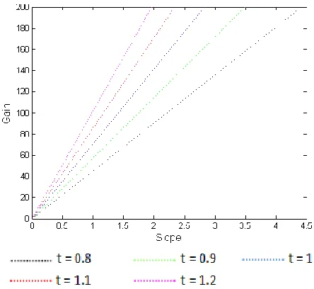
(B) Influence of Tap-Changing Transformer on SVC Controller Gain versus Slope Relation.
[image:6.612.334.556.294.498.2]
Figure: 11 SVC controller drop Slope/Gain relation in the presence of tap-changing transformer in order to maintain the load voltage
constant.
Fig. 4.11 shows the SVC controller drop slope/gain relation plots for five off-nominal transformer tap ratio‘s that are t = 0.8, 0.9, 1, 1.1 and 1.2. They are plotted for reference voltage VR= 1.0 p.u and load terminal voltage Vt
= 0.99 p.u. For the same gain value, different slops should be adjusted with different transformer tap ratios in order to keep load voltage constant at 0.99 p.u. Xc of the
International Journal of Emerging Technology and Advanced Engineering
Website: www.ijetae.com (ISSN 2250-2459,ISO 9001:2008 Certified Journal, Volume 3, Issue 12, December 2013)
223
[image:7.612.56.280.148.366.2]
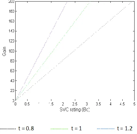
Fig. 4.12 Compensator design parameter/controller gain relation in the presence of tap-changing transformer
For a slope of 0.2, the SVC controller gain/compensator rating (1/XC) relation is plotted in fig. 4.12 with three
off-nominal tap ratio‘s as t = 0.8, 1 and 1.2. The plot shows different compensator power ratings are required at each compensator controller gain, in order to keep load voltage constant in the presence of automatic tap-changing transformer of different off-nominal tap ratios.
TABLE- III
COMPENSATOR RATING AT DIFFERENT GAIN (P.U)
Table-1.3 shows the needed SVC ratings corresponding to different controller gain, and different transformer off-nominal tap ratios.
V. CONCLUSION
Presence of only tap-changing transformers does not improve voltage stability significantly. They do affect the voltage levels and slightly the critical voltages, but do not affect the maximum powers corresponding to these critical voltages. Therefore, tap-changing transformer at the load terminals can slightly contribute to its voltage stability.
Presence of Static VAR Compensator with different controller gains can increase the maximum load powers several times as compared to its original value without Static VAR Compensator.
There is an interaction between the transformer off-nominal tap ratio and the compensator controller gains and reference voltages, in order to keep the load node voltage constant at all loading conditions.
The compensator ratings is affected with presence of tap changing transformer, the fixed reactance of the TCR type compensator changes significantly with the presence of tap-changing transformer. Certain transformer off-nominal tap ratios minimizes the SVC needed ratings, i.e. in the presence of tap-changing transformer, the SVC rating required to keep the load voltage constant at certain value is reduced significantly.
REFERENCES
[1] Enrique Acha and Claudio R. Fuerte-Esquivel, FACTS Modelling and Simulation in Power Networks, John wiley and sons, 2004 [2] A.R. Bergen and V. Vittal, Power Systems Analysis, Pearson, India,
2004.
[3] W.D. Stevenson and J.J. Grainger, Power System Analysis, TMH, India, 1998.
[4] Hiroshi Ohtsuki, Akihiko Yokoyama, Yasuji Sekine, ―Reverse action of on-load tap-changer in association with voltage collapse‖, IEEE trans. Power syst., Vol.6. No. 1, 1991.
[5] S. Milan, Calovic, Modeling and analysis of under load tap-changing transformer control systems. IEEE trans, 103 (7) (1984) 1909-1913.D.
[6] M.Z. El-Sadek,et al, ―Enhancement of steady-state voltage stability by using static VAR compensators‖, Electric Power System Research, 43 (1997) 179-185.
[7] Mark Ndubuka NWOHU, ―Voltage Stability Improvement using Static VAR Compensator in Power Systems‖, Leonardo Journal of Sciences ISSN 1583-0233, P 167-172, issue 14 January-June 2009 [8] Dr. N Kumar, Dr. A Kumar, P.R. Sharma, ―Determination of
optimal amount of location of series compensation and SVC for an AC Transmission System‖, IE (I) Journal-EL, Vol. 83, March 2003. Sr.No. Gain
Off-nominal tap ratio
t = 0.8
Off-nominal tap ratio
t = 1.0
Off-nominal tap ratio
t = 1.2
1 50 1.2 0.7 0.56
2 70 1.7 1.08 0.75
3 100 2.43 1.57 1.07
International Journal of Emerging Technology and Advanced Engineering
Website: www.ijetae.com (ISSN 2250-2459,ISO 9001:2008 Certified Journal, Volume 3, Issue 12, December 2013)
224
[9] M.Z. El-Sadek,et al, ―Series capacitor combined with static VAR compensator for enhancement of steady-state voltage stability‖, Electric Power System Research, 44(1998) 137-143.
[10] M.Z. El-Sadek, M.M. Dessouky, G.A. Mahmoud, W.I. Rashed, ―Combined use of tap-changing transformer and static VAR compensator for enhancement of steady-stat voltage stabilities‖, Electric Power System Resarch, 45 (1998) 47-55.
[11] Farag Ali El-Sheikhi, Mabruk Saad, Saleh Omar Osman,Khalil M. El- Arroudi, ―Voltage Stability Assessment Using Modal Analysis of Power Systems including Flexible AC Transmission System (FACTS)‖, Eastern Generation & transmission Administration. GECOL, IEEE 2003.
[12] Hingorani, N. G. and Gyugyi. L. (1999), Understanding FACTS: Concept and Technology of Flexible AC Transmission Systems. IEEE Press.
[13] Kundur P. S., Power system stability and control, EPRI McGraw-Hill, ISBN 0-07-035958-X, 1994.
[14] Padiar K.R. ―FACTS controller in power transmission and distribution”New Age International Publication-2007.
[15] Mathur R.M.,Verma R.K.‖Thyristor based FACTS controllers for electrical transmission system‖ IEEE Press-2002