International Journal of Emerging Technology and Advanced Engineering
Website: www.ijetae.com (ISSN 2250-2459, ISO 9001:2008 Certified Journal, Volume 7, Issue 3, March 2017)
15
Power Saving Using PV Array and Boost Converter when used
with A VFD
Solanki Digvijaysinh
1, Nitesh Agrawal
21
M.Tech Scholar, 2Assistant Professor, Aravali Institute of Technical Studies, Udaipur, Rajasthan, INDIA
Abstract— Induction motors (IM) are, nowadays, widely used in variable speed motive power applications along with Variable Frequency Drives (VFD). Power saving is also a major application of VFD. Instead of wasting power in damping, IM takes only desired power from grid when used with VFD. Further if we feed DC power to the DC link of VFD, it will take less power from the power grid i.e. it further saves valuable electrical power. In this research it is tried to feed VFD directly on its DC link from Photovoltaic (PV) cell array. For this, simulation is carried out on Matlab/Simulink software. To match voltage requirement and DC power control at its maximum value from PV array, a boost converter is placed in between. It is observed that by changing modulation index of boost converter, power sharing between mains and PV array changes. This results in to major power saving without the need of maintenance hungry batteries.
Keywords— Boost Converter, DC link, Matlab/Simulink, PV array, VFD.
I. INTRODUCTION
To meet global energy demand and get rid of pollution emitted by fossil fuel, more research work is headed towards non conventional energy sources like solar, wind, tidal energy etc. For generation of DC power, these renewable sources are the best options, because of their benefits meet with today’s global requirements [1]. Concept of this research is to inject solar power directly to the DC link of a Variable Frequency Drive (VFD). VFD is used to control speed and torque of a Three Phase Induction Motor (3ØIM). Around 70% of power generated worldwide is consumed by 3ØIM. So, if we can save small amount of electrical power on each 3ØIM, it will be a huge saving indeed. A reason for injection of DC power directly on the DC link of a VFD is to eliminate need of injection and retrieval of AC power to and from power grid system. With this, for small scale, solar system can be employed near to the load end.
The use of renewable energy source can make positive impact on environment. Energy demand is increasing day by day and use of fossil fuel is increasing because of the same resulting in dangerous pollution level.
The only alternative left for us is to use maximum amount of renewable energy sources. From renewable energy solar and wind are attracting sector for researcher as alternative sources in recent year [1]. The renewable energy sources are more important contributors to the total energy consumption in the world. The demand for solar energy has increased by 20% to 25% over past 20 years [9]. Research activities are being conducted to gain further improvement in their cost, efficiency and reliability.
Energy from Sun we get is in the form of irradiation. After passing through atmosphere, a square meter on the earth’s surface can receive as much as 1 kW of solar power, averaging about 0.5 kW during all daylight hours [12]. Photovoltaic (PV) system is recognised to be in the fore front in renewable electric power generation [11]. Photovoltaic cell converts sunlight directly to electricity [9]. In this research, because of distinct advantages, PV system is used as a DC power generator employed at load end. These PV systems generate comparatively low voltage w. r. t. the required voltage on DC link of VFD. This can be bridged by using proper DC-DC boost converter [6].
International Journal of Emerging Technology and Advanced Engineering
Website: www.ijetae.com (ISSN 2250-2459, ISO 9001:2008 Certified Journal, Volume 7, Issue 3, March 2017)
[image:2.612.65.275.128.302.2]16
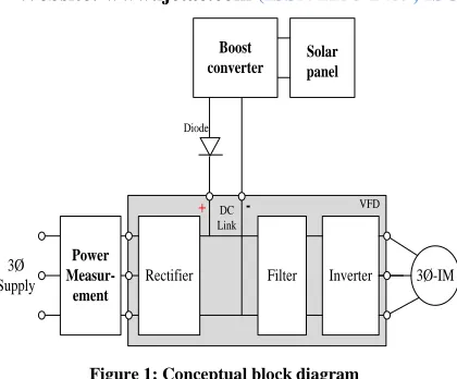
Solar panel + -Inverter Filter Rectifier 3Ø-IM 3Ø Supply Diode Boost converter VFD DC Link Power Measur-ementFigure 1: Conceptual block diagram
This arrangement is suitable for all type of VFDs. Controlling action can achieve by own controller at inverter stage. As shown in Figure 1 connections can be establish for all devices mentioned, and as result, power saving with change in %duty ratio can be obtain.
II. PHOTOVOLTAIC ARRAY MODELING
PV cell consist of a P-N junction fabricated in a thin layer or wafer [11]. PV cell can be manufactured by various technologies with different cell parameters [5]. Photovoltaic cell is a basic unit of a PV system. Cell is a current source in parallel with diode. As shown Figure 2(a) ideal single diode model and figure 2(b) practical model with Rs and Rp.
ID Iph I V +
-Figure 2(a): Ideal single diode model
I
DI
phI
V
+
-R
pR
sI
pFigure 2(b): Practical model with Rs and Rp
By applying Kirchhoff law, equation of current is obtain [5]:
I
I
I
I
ph d p (1)Ip is current flowing in Rp [5].
For single PV cell, output current of module is according to equation (2) [5, 10]:
R
R
I
V
R
I
V
I
I
I
p S S o ph a 1exp (2)
Practically the output of single PV cell is not sufficient for almost application, Therefore to increase capacity of PV system, single cell module should be connect in series and parallel combination. There are some limitation for connecting numbers of series and parallel connection according to system. If Np consider as the number of cells connected in parallel and Ns as the number of cells connected in series. Parallel connection increase in current capacity and series connection increase voltage capacity of PV system [10].
I
N
I
ph,final p ph (3)I
N
I
o,final p o (4)n
N
n
final p (5)R
N
N
R
s p s finals,
(6)
[image:2.612.85.237.489.581.2]International Journal of Emerging Technology and Advanced Engineering
Website: www.ijetae.com (ISSN 2250-2459, ISO 9001:2008 Certified Journal, Volume 7, Issue 3, March 2017)
17
R R N N I V N R N N I V I N I N I p s s S o ph p s a p s pp exp 1
(7)
PV array can be implement in Matlab based on mathematical equation. PV characteristics namely short-circuit current (Isc), open-circuit voltage (Voc) and maximum power point (Pmp = Imp * Vmp) [10].
III. BOOST CONVERTER
[image:3.612.344.548.298.444.2]Boost converter are used to obtain higher DC voltage output with lower DC voltage input. It can be used as front end converter for battery sources, photovoltaic solar systems and fuel cell [7].
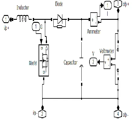
Figure 3: Basic boost converter model
In Figure 3 basic model of boost converter is shown, at point 1 & 2 converter takes input from output of PV system, connecting port indicated as i/p+ & i/p -. Output obtained from connecting port 3 (o/p +) and 4 (o/p -). In this matlab model, MOSFET is use as a switch and gate pulse is given by in port. Ammeter measures output current by out port 1 and output voltage measured by out port 2.
Output voltage of boost converter can vary by changing in switching of MOSFET. There are various techniques of switch ON and OFF (duty cycle) to obtain desire output voltage [7]. PWM is popular method and it is easily implement. With reference to time width of pulse is change, mean duty ratio is change. Output of converter is depends on duty ratio.
IV. VARIABLE FREQUENCY DRIVE
As its name device control frequency and voltage. VFD takes 3-phase AC supply as input, at first stage rectify that and forward to filter unit via DC link, then final stage invert DC supply to controlled 3-phase AC supply. Output of drive is supplying from inverter section and for controlling of output supply, triggering of inverter circuit done with different techniques. Most of controlling activity perform at inverter stage, and V/F ratio taken as reference [8]. For controlling output, VFD has various parameter. According to parameter programed in VFD, it takes necessary controlling actions and as result variation in output of VFD found.
Figure 4: Basic VFD model
Model shown in Figure 4 is develop in MATLAB. Connecting port 3, 4 and 5 incoming supply for VFD and 6, 7 and 8 are outgoing of VFD. Connecting port 1 is +DC terminal and 2 is –DC terminal. In port 1 is triggering signal from PWM generator, in physical VFD it is internal circuit. Out port 1 is take DC link voltage value.
V. INDUCTION MOTOR
Three phase induction motor considered is rated at 415V, 50Hz, 750W (1HP).
VI. SIMULATION AND RESULT
[image:3.612.59.278.327.532.2]International Journal of Emerging Technology and Advanced Engineering
Website: www.ijetae.com (ISSN 2250-2459, ISO 9001:2008 Certified Journal, Volume 7, Issue 3, March 2017)
[image:4.612.68.268.136.284.2]18
Figure 5: Motor Load vs. Main power (without PV system)
With change of load at motor, power taken by motor is increasing as Figure 5. It depends on VFD and load. With increment in load, over all losses and supply current are also increased.
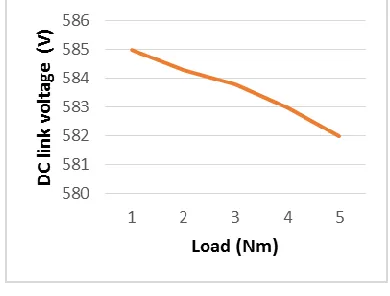
Figure 6: Load vs. DC link voltage (without PV system)
As load increase input power increase, but voltage of DC link decreased, Figure 6 shows that voltage decrement. Both Figure 5 and Figure 6 observed without connecting PV system and boost converter.
[image:4.612.331.553.170.436.2]Figure 7 shows change in boost output voltage with change in duty ratio of boost converter switch. To start power supplying through solar system, duty ratio play important roll. Set point voltage and DC link voltage taken as reference and feedback respectively, to decide duty ratio. With higher capacity of solar system, desire level of voltage can achieve by lower value of duty ratio.
Figure 7: Duty ratio vs. Boost output voltage (with resistive load of 1KOhm)
Figure 8: Duty ratio vs. Solar power (with resistive load of 1KOhm)
Model of PV array developed for power rating of 60 W and 20 V. Seven PV array are connected in series to increase final output voltage, hence total power rating is 420 W. Maximum power can extract from PV can controlled by duty ratio as shown in Figure 8.
[image:4.612.70.265.353.501.2] [image:4.612.334.549.524.682.2]International Journal of Emerging Technology and Advanced Engineering
Website: www.ijetae.com (ISSN 2250-2459, ISO 9001:2008 Certified Journal, Volume 7, Issue 3, March 2017)
19
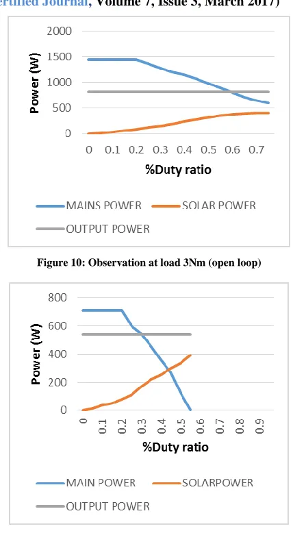
As duty ratio increase and power supply from PV system and boost converter start supplying, then main power start reducing. At maximum power from converter main supply power taken by drive is minimum. Reduction in main power shows that energy saving at supply line. With desire capacity of PV system, full power can be supply through it. Figure 9 shows main power is constant at lower duty ratio, because at lower duty ratio output voltage of boost converter is lower than DC link voltage so Power can’t flow through PV system.TABLE 1
OBSERVATION FOR LOAD 3NM
[image:5.612.335.549.124.513.2]Observation shown in Table 1 is taken during simulation. Graph shown in Figure 10 developed from Table 1. For whole simulation output power is constant for same load. As change in duty ratio from 0 to 0.2 main power is constant and solar power increasing. After duty ratio 0.2 output voltage of boost converter slide higher then DC link voltage of VFD, so it start supplying power from PV system through boost converter. Power supply from PV system increase with increase in duty ratio to maximum value. Power supplied by PV system increase, power taken from main supply is reduce. After maximum power, if duty ratio increase, power of PV system start reducing.
Figure 10: Observation at load 3Nm (open loop)
Figure 11: Observation at load 1Nm (open loop)
Figure 11 & 12 both are develop with observation like Table 1, but with different load. Duty ratio of boost converter is main factor to control power flow between PV system and DC link of VFD. With the help of feedback of DC link voltage and reference set point, duty ratio can be controlled as require. For protection from reverse current, diode is placed between boost converter output and DC link terminal of VFD.
[image:5.612.56.279.275.537.2]International Journal of Emerging Technology and Advanced Engineering
Website: www.ijetae.com (ISSN 2250-2459, ISO 9001:2008 Certified Journal, Volume 7, Issue 3, March 2017)
[image:6.612.61.275.108.633.2]20
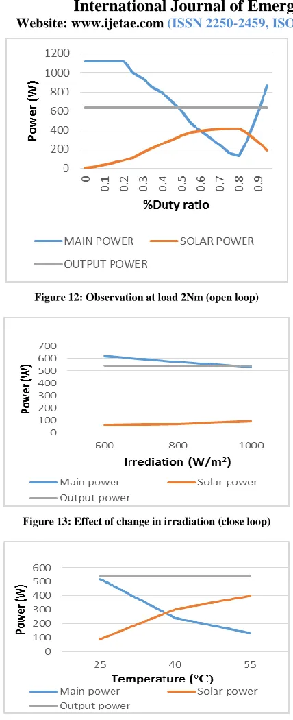
Figure 12: Observation at load 2Nm (open loop)
Figure 13: Effect of change in irradiation (close loop)
Figure 14: Effect of change in temperature (close loop)
Figure 13, 14 and 15 are observed with close loop control with PID controller for boost converter, and with change in irradiation, temperature and load. As change in irradiation is occur, output of PV system also change, then PID takes necessary actions and power saving also change according to it.
With constant irradiation and load, first temperature was taken at its base value 25°C and increase. As observe in figure 14, output power of PV system increase with temperature, so main power reduce and power saving increase. PID controller control output power of converter to its maximum value. Minor change in DC link voltage observed with increasing power saving.
[image:6.612.336.551.278.413.2]Figure 15 shows observation with change in load and at constant irradiation & temperature. As load increase, main power increase and PID controller takes necessary actions accordingly and takes PV and boost output to its maximum capacity.
Figure 15: Effect of change in load (close loop)
VII. AREA OF APPLICATION
With growth of industries, area of application of IM with VFD also increase. This concept can employ for all type of load duty. In industries like food processing, metal, cement etc. are the area with higher possibility. Area of application not limited to industries only, it can be applicable for transports station, malls, hospitals, commercial buildings etc. where the energy saving is a major concern.
VIII. CONCLUSION
International Journal of Emerging Technology and Advanced Engineering
Website: www.ijetae.com (ISSN 2250-2459, ISO 9001:2008 Certified Journal, Volume 7, Issue 3, March 2017)
21
REFERENCES[1] T.K. Roy, M.A. Mahmud, A.m. T. Oo and M.E. Haque, are with the School of Engineering, Deakin University, VIC 3216.
[2] P Sadasivam, M Kumaravel, Krishna Vasudevan and Ashok Jhunjhunwala, Indian Institute of Technology Madras, Chennai, Tamilnadu, 600036, India.
[3] S.R. BHAT, ANDRE PITTET, AND B.S. SONDE, IEEE transaction on industry application, vol. IA-23, No.6, November/December 1987
[4] Geoffrey Walker ―Evaluating MPPT converter topologies using a MATLAB PV model.‖ Journal of electrical and electronics engineering, Australia – January 2001.
[5] Habbati Bellia, Ramdani Youcef, Moulay Fatima ―A detailed modelling of photo voltaic module using MATLAB‖ NIRAG journal of Astronomy and Geophysics, 16 May 2014.
[6] F. Martinez and M. Castiblanco, ―Increase the Boost Converter Performance using Genetic Algorithms‖ Ref. no. W09-0033. [7] G. Seshgiri Rao, S.raghu, N. Rajasekaran, ―Design of Feedback
Controller for Boost Converter Using Optimization Technique‖ International Journal of Power electronics and Drive System (IJPEDS) Vol.3 No.1, March 2013, pp. 117~128 ISSN: 2088-8694.
[8] Krupa Gandhi, K.L.Mokariya, Deepa Karvat, ―Simulation of PWM inverter for VFD application Using MATLAB‖ International Journal of Engineering Research and Development e-ISSN: 2278-067X, p-ISSN: 2278-800X, vol 10, Issue 4 (April 2014), PP. 94-103 [9] Tarak Salmi, Mounir Bouzguenda, Adel Gastli, ahmed Masmoudi,
―MATLAB/SIMULINK based Modelling of Solar Photovoltaic Cell‖ International journal of Renewable energy research, Tarak Salmi et al., Vol.2, No.2, 2012
[10] MBOUMBOUE Edouard, Donatien NJOMO, ―International Journal of Emerging Technology and advanced engineering, ISSN 2250-2459, Volume 3, Issue 9, September 2013.
[11] Natarajan Pandiarajan, Raganath Muthu, and ―Mathematical modelling of photovoltaic module with SIMULINK‖ Conference Paper – February 2011, DOI: 101109/ICEES.2011.5725339-Source: IEEE Xplore.