Efficient structurebased models for the
McKibben contraction pneumatic muscle
actuator : the full description of the
behaviour of the contraction PMA
AlIbadi, A, NeftiMeziani, S and Davis, ST
http://dx.doi.org/10.3390/act6040032
Title
Efficient structurebased models for the McKibben contraction pneumatic
muscle actuator : the full description of the behaviour of the contraction
PMA
Authors
AlIbadi, A, NeftiMeziani, S and Davis, ST
Type
Article
URL
This version is available at: http://usir.salford.ac.uk/id/eprint/44173/
Published Date
2017
USIR is a digital collection of the research output of the University of Salford. Where copyright
permits, full text material held in the repository is made freely available online and can be read,
downloaded and copied for noncommercial private study or research purposes. Please check the
manuscript for any further copyright restrictions.
actuators
Article
Efficient Structure-Based Models for the McKibben
Contraction Pneumatic Muscle Actuator: The Full
Description of the Behaviour of the Contraction PMA
Alaa Al-Ibadi * ID, Samia Nefti-Meziani and Steve Davis
School of Computing, Science & Engineering, University of Salford, Salford M5 4WT, Greater Manchester, UK; [email protected] (S.N.-M.); [email protected] (S.D.)
* Correspondence: [email protected] or [email protected]; Tel.: +44-743-846-2585
Received: 30 August 2017; Accepted: 23 October 2017; Published: 27 October 2017
Abstract:To clarify the advantages of using soft robots in all aspects of life, the effective behaviour of the pneumatic muscle actuator (PMA) must be known. In this work, the performances of the PMA are explained and modelled with three formulas. The first formula describes the pulling force of the actuator based on the structure parameters; furthermore, the formula presented is the generalised contraction force for wholly-pneumatic muscle actuators. The second important model is the length formula, which is modified to our previous work to fit different actuator structures. Based on these two models, the stiffness of the actuator is formulated to illustrate its variability at different air pressure amounts. In addition, these formulas will make the selection of proper actuators for any robot arm structure easier using the knowledge gained from their performance. On the other hand, the desired behaviour of this type of actuator will be predefined and controlled.
Keywords:contraction actuators; modelling; soft robotics; pulling force; stiffness
1. Introduction
An interaction between a robot arm and humans represents an important issue in industrial and medical applications, which has to be safe and compliant during all probable situations, such as control failure, human error, or any unexpected error in the robot arm itself. On the other hand, the performance of the robot, including accuracy and rapidity, remains necessary as the task requirement [1]. Tonietti, et al. [2] explain that the machines must be safe against all conceivable accidents whilst they interact with humans. Another important target is their behaviour, which can frequently be expressed as a speed of motion. The designers used to consider the safety and the performance as two separate features [3].
To overcome this problem, many sensors are used in the rigid robot arm and an active control is required. This solution is costly and not adequately dependable [2].
Many types of variable stiffness actuators (VSA) have been presented during the last few years. Some of them reduced the probability of risk of injury. In spite of their excellent performance, rigidity is the main characteristic of this type of actuator. This led to the invention of sufficiently soft, high-stiffness actuators. In recent years there has been a substantial increase in designing, modelling, and constructing (biologically-based) continuum robots that provide new robotic behaviours, and offer an infinite number of robot applications [4,5]. The pneumatic muscle actuator (PMA), which is the base of such types of robots, has numerous positives over ordinary pneumatic cylinders, such as the high force in comparison to its weight, low workspace requirement, high flexibility to construct [6,7], adaptable installation possibilities, minimum consumption of compressed air, accessibility of different measurements, low cost, and being safe for human use [6,8]. For these exceptional features, the PMA has been considered as an appropriate actuator to use behind electrical and hydraulic actuators.
Actuators2017,6, 32 2 of 15
Despite its distinct positives, the PMA shows extremely nonlinear features [9]. This nonlinearity is caused by the elastic-viscous properties of the inner rubber tube, the compressibility of air, and the structure of the complex behaviour of the PMA outer covering [7]. Furthermore, the hysteresis performance is due to the inner rubber tube, which results in different performances of the PMA during different pressurizing conditions [6]. This behaviour increases the complexity of the system model and its control [4].
Numerous studies have been done to study and model the performances and the characteristics of such types of actuators. Among these studies, Takosoglu, et al. [10] outline the static performance of the PMA. On the other hand, the Tondu and Lopez formula [9] and the Chou and Hannaford model [11] are extensively used. Both models are established on the theory of the virtual works of the cylindrical form and the zero walls of the inner rubber tube and the braided sleeve. Their force formulas have been modified many times to reduce the error between the theoretical and exact force values. The force formula has been enhanced by Al-Ibadi, et al. [12] by considering the amount of the pressure required to establish the tensile force. The hysteresis has been considered by numerous researchers [13,14]. In spite of these works, an exact force and position model do not yet exist. As a result, the control strategies have to be modified to overcome the difficulties for the single actuator, as well as for the multiple PMAs.
In this article, two of the major previous assumptions are considered, the thickness of the actuator and the friction between the inner rubber tube and the braided sleeve. A general structure-based force formula for the contraction actuator is presented, and then a modification of the previous length formula is generalized. Furthermore, the variable stiffness of the inner tube has been clarified it is influencing to the stiffness of the PMA at variety pressurised conditions.
2. Structure of the Pneumatic Muscle Actuator
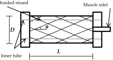
Joseph L. McKibben, in the 1950s, developed the pneumatic muscle actuator (PMA), which is simply made from a latex tube bounded by an expandable sleeve [11]. The simplicity of the McKibben artificial actuator structure presented its use in many applications. Its operational basics are simple: the bounded tension of the inner rubber tube is converted into a vertical pulling force [15]. Different air pressure produces different pulling force values and this axial force is subject to the construction of the PMA Figure1shows the general construction of the pneumatic muscle actuator.
WhereLis the length of the actuator,Dis the diameter, andθdenotes the braided angle, which it is measured between braided strand (b) and the vertical line, its value varies from 0◦to 180◦based on the construction and is the main aspect in the PMA’s actions. The initial values are defined asL0,D0, andθ0, respectively.
The length, diameter, and the braided angle change with the amount of the air pressure inside the muscle until the braided angle reaches 54.7◦, which represents the critical value at which the contraction force is zero [9,11,12].
The contraction pneumatic muscle actuators act similarly to biological muscle: the contraction behaviour occurs when the diameter of the inner rubber tube increases due to the air pressure, which leads to producing a specific amount of pulling force.
Actuators 2017, 6, 32 2 of 15
Despite its distinct positives, the PMA shows extremely nonlinear features [9]. This nonlinearity is caused by the elastic-viscous properties of the inner rubber tube, the compressibility of air, and the structure of the complex behaviour of the PMA outer covering [7]. Furthermore, the hysteresis performance is due to the inner rubber tube, which results in different performances of the PMA during different pressurizing conditions [6]. This behaviour increases the complexity of the system model and its control [4].
Numerous studies have been done to study and model the performances and the characteristics of such types of actuators. Among these studies, Takosoglu, et al. [10] outline the static performance of the PMA. On the other hand, the Tondu and Lopez formula [9] and the Chou and Hannaford model [11] are extensively used. Both models are established on the theory of the virtual works of the cylindrical form and the zero walls of the inner rubber tube and the braided sleeve. Their force formulas have been modified many times to reduce the error between the theoretical and exact force values. The force formula has been enhanced by Al-Ibadi, et al. [12]by considering the amount of the pressure required to establish the tensile force. The hysteresis has been considered by numerous researchers [13,14]. In spite of these works, an exact force and position model do not yet exist. As a result, the control strategies have to be modified to overcome the difficulties for the single actuator, as well as for the multiple PMAs.
In this article, two of the major previous assumptions are considered, the thickness of the actuator and the friction between the inner rubber tube and the braided sleeve. A general structure-based force formula for the contraction actuator is presented, and then a modification of the previous length formula is generalized. Furthermore, the variable stiffness of the inner tube has been clarified it is influencing to the stiffness of the PMA at variety pressurised conditions.
2. Structure of the Pneumatic Muscle Actuator
Joseph L. McKibben, in the 1950s, developed the pneumatic muscle actuator (PMA), which is simply made from a latex tube bounded by an expandable sleeve [11]. The simplicity of the McKibben artificial actuator structure presented its use in many applications. Its operational basics are simple: the bounded tension of the inner rubber tube is converted into a vertical pulling force [15]. Different air pressure produces different pulling force values and this axial force is subject to the construction of the PMA Figure 1 shows the general construction of the pneumatic muscle actuator.
Where L is the length of the actuator, D is the diameter, and θ denotes the braided angle, which it is measured between braided strand (b) and the vertical line, its value varies from 0° to 180° based on the construction and is the main aspect in the PMA’s actions. The initial values are defined as L0, D0, and θ0, respectively.
The length, diameter, and the braided angle change with the amount of the air pressure inside the muscle until the braided angle reaches 54.7°, which represents the critical value at which the contraction force is zero [9,11,12].
[image:3.595.206.395.644.745.2]The contraction pneumatic muscle actuators act similarly to biological muscle: the contraction behaviour occurs when the diameter of the inner rubber tube increases due to the air pressure, which leads to producing a specific amount of pulling force.
Figure 1. The structure of the pneumatic muscle actuator.
Inner tube
Braided strand Muscle inlet
L
ᶿ
D
Actuators2017,6, 32 3 of 15
3. Operation of the PMA
The principle operation of the contraction pneumatic muscle can be fully explained in two situations: (a) variable air pressure at a fixed, attached load; and (b) varying the load with constant air pressure. The diameter of the braided sleeve will increase and, as a result, the diameter of the PMA rises by incrementing the air pressure, while the actuator length will decline to reach the maximum contraction ratio (ε). Equation (1) gives the contraction ratio expression:
ε= L0−L
L0
(1)
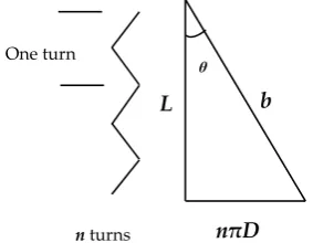
whereL0is the initial actuator length andLis the length of the PMA under the pressurised condition. In Figure2,nrepresent the total amount of strand turns for the whole actuator.nis a constant value for each actuator and it depends on the length and specification of the braided sleeve. The other coefficients, such asL,D, andθ, are varied due to the amount of air pressure and the construction of the air muscle. In the first operation, as is shown in Figure3, the actuator is fixed at the upper end and a specific load is attached to its free end. The air pressure slowly increases from zero bar to a certain value. Due to the similarity between the pneumatic muscle and the biological muscle, the contraction in the first operation is called isotonic, and measuring the contraction at the second operation is called isobaric [10].
Actuators 2017, 6, 32 3 of 15
3. Operation of the PMA
The principle operation of the contraction pneumatic muscle can be fully explained in two situations: (a) variable air pressure at a fixed, attached load; and (b) varying the load with constant air pressure. The diameter of the braided sleeve will increase and, as a result, the diameter of the PMA rises by incrementing the air pressure, while the actuator length will decline to reach the
maximum contraction ratio (ε). Equation (1) gives the contraction ratio expression:
= − (1)
where L0is the initial actuator length and L is the length of the PMA under the pressurised condition.
In Figure 2, n represent the total amount of strand turns for the whole actuator. n is a constant
value for each actuator and it depends on the length and specification of the braided sleeve. The other
coefficients, such as L, D, and θ, are varied due to the amount of air pressure and the construction of
[image:4.595.227.369.354.464.2]the air muscle. In the first operation, as is shown in Figure 3, the actuator is fixed at the upper end and a specific load is attached to its free end. The air pressure slowly increases from zero bar to a certain value. Due to the similarity between the pneumatic muscle and the biological muscle, the contraction in the first operation is called isotonic, and measuring the contraction at the second operation is called isobaric [10].
Figure 2. The parameters of the PMA.
At a definite pressure value P1, a contracting force will start to lift the fixed load until it reaches
[image:4.595.185.412.534.713.2]the balance point; at this point the contraction force is similar to the mass weight [16].
Figure 3. Isotonic characteristic of the pneumatic muscle actuator.
ᶿ
L
nπD b
n turns One turn
V2
P2
M
VminP=0
M
LmaxL2
L1
M
V1P1
Figure 2.The parameters of the PMA.
At a definite pressure valueP1, a contracting force will start to lift the fixed load until it reaches the balance point; at this point the contraction force is similar to the mass weight [16].
3. Operation of the PMA
The principle operation of the contraction pneumatic muscle can be fully explained in two situations: (a) variable air pressure at a fixed, attached load; and (b) varying the load with constant air pressure. The diameter of the braided sleeve will increase and, as a result, the diameter of the PMA rises by incrementing the air pressure, while the actuator length will decline to reach the
maximum contraction ratio (ε). Equation (1) gives the contraction ratio expression:
= − (1)
where L0is the initial actuator length and L is the length of the PMA under the pressurised condition.
In Figure 2, n represent the total amount of strand turns for the whole actuator. n is a constant
value for each actuator and it depends on the length and specification of the braided sleeve. The other
coefficients, such as L, D, and θ, are varied due to the amount of air pressure and the construction of
the air muscle. In the first operation, as is shown in Figure 3, the actuator is fixed at the upper end and a specific load is attached to its free end. The air pressure slowly increases from zero bar to a certain value. Due to the similarity between the pneumatic muscle and the biological muscle, the contraction in the first operation is called isotonic, and measuring the contraction at the second operation is called isobaric [10].
Figure 2. The parameters of the PMA.
At a definite pressure value P1, a contracting force will start to lift the fixed load until it reaches
the balance point; at this point the contraction force is similar to the mass weight [16].
Figure 3. Isotonic characteristic of the pneumatic muscle actuator.
ᶿ
L
nπD b
n turns One turn
V2
P2
M
VminP=0
M
LmaxL2
L1
M
V1P1
Actuators2017,6, 32 4 of 15
The volume of the PMA will rise toV1and the length reduces toL1. An increment in the pressure toP2leads to an increase in the actuator’s volume and creates more contraction toL2, and the air pressure will increase to its maximum value which is subject to the structure of the actuator.
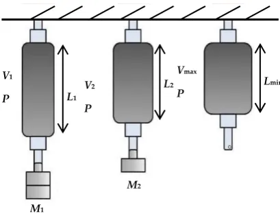
The second action situation is pressurising the PMA at constant air pressure P. Varying the attached load, as shown in Figure4, leads to changes in the behaviour of the PMA. Reducing the load from M1 to M2, and then to no load, will raise the volume and reduce the length of the actuator [16]. The multiple lengths and volumes produced depend on the amount of the air pressure inside the muscle.
Actuators 2017, 6, 32 4 of 15
The volume of the PMA will rise to V1 and the length reduces to L1. An increment in the pressure
to P2 leads to an increase in the actuator’s volume and creates more contraction to L2, and the air
pressure will increase to its maximum value which is subject to the structure of the actuator.
The second action situation is pressurising the PMA at constant air pressure P. Varying the
attached load, as shown in Figure 4, leads to changes in the behaviour of the PMA. Reducing the load
from M1 to M2, and then to no load, will raise the volume and reduce the length of the actuator [16].
[image:5.595.194.399.203.359.2]The multiple lengths and volumes produced depend on the amount of the air pressure inside the muscle.
Figure 4. Isobaric characteristic of the pneumatic muscle actuator.
4. Presented Force Formula
Tatlicioglu, et al. [17] show that, in most engineering systems, it is important to have an accurate model to improve the behaviour of the system. In recent years there have been numerous studies conducted to mathematically model the PMAs. The work was done to relate both the air pressure and the length of the PMA to the generated pulling force of contraction muscles. Numerous factors have major effects on the model, such as the properties of the material used in the PMA construction, length, diameter, braided angle, and air pressure. Understanding the relationship between these factors leads to constructing accurate models, especially for control requirements [16].
Important work was done by Chou and Hannaford [11]. They constructed a model for the contraction pneumatic muscle actuator under the following assumptions: (a) the shape of an actuator is cylindrical; (b) there is always a contact between the braided sleeve and the surface of the inner tube; (c) neglecting the friction between the tube and the braided sleeve; and (d) ignoring the latex forces of the tube.
The second widely-used model was formulated by Tondu and Lopez [9]. Their contraction force formula was derived under the following assumptions: (a) the shape of the PMA is a perfect cylinder with zero wall thickness; (b) there is contact between the inner rubber tube and the braided sleeve; (c) the braided strand length is constant; (d) there is no friction between the tube and the sleeve; and (e) the latex tube force is neglected.
Other research is being conducted to overcome the above assumptions for the presented contractor
force models. Tondu and Lopez [9] modified their model by adding the shape correction factor (q ≤ 1).
There are two options to select the correction factor: (a) the constant value, which depends on the material, and (b) the variable value, which depends on the pressure.
Kang, et al. [18] propose a formula to the correction factor as follows:
= 1 + (2)
where c1 and c2 are positive constants. From this equation, the correction factor becomes 1 at
maximum air pressure, where the actuator shape is cylindrical. M1
V1
P L1
M2
V2
P
L2
Vmax
P
Lmin
Figure 4.Isobaric characteristic of the pneumatic muscle actuator.
4. Presented Force Formula
Tatlicioglu, et al. [17] show that, in most engineering systems, it is important to have an accurate model to improve the behaviour of the system. In recent years there have been numerous studies conducted to mathematically model the PMAs. The work was done to relate both the air pressure and the length of the PMA to the generated pulling force of contraction muscles. Numerous factors have major effects on the model, such as the properties of the material used in the PMA construction, length, diameter, braided angle, and air pressure. Understanding the relationship between these factors leads to constructing accurate models, especially for control requirements [16].
Important work was done by Chou and Hannaford [11]. They constructed a model for the contraction pneumatic muscle actuator under the following assumptions: (a) the shape of an actuator is cylindrical; (b) there is always a contact between the braided sleeve and the surface of the inner tube; (c) neglecting the friction between the tube and the braided sleeve; and (d) ignoring the latex forces of the tube.
The second widely-used model was formulated by Tondu and Lopez [9]. Their contraction force formula was derived under the following assumptions: (a) the shape of the PMA is a perfect cylinder with zero wall thickness; (b) there is contact between the inner rubber tube and the braided sleeve; (c) the braided strand length is constant; (d) there is no friction between the tube and the sleeve; and (e) the latex tube force is neglected.
Other research is being conducted to overcome the above assumptions for the presented contractor force models. Tondu and Lopez [9] modified their model by adding the shape correction factor (q≤1). There are two options to select the correction factor: (a) the constant value, which depends on the material, and (b) the variable value, which depends on the pressure.
Kang, et al. [18] propose a formula to the correction factor as follows:
q Pg=1+c1e−c2Pg (2)
Al-Ibadi, et al. [12] argue that the pulling force of the contractor PMA does not generate an air pressure value less than, or equal to, 0.45 bar.
Referring to Figure 3, and under the virtual work theory, the input work (Win) for the
McKibben’s muscle under air pressure supply is:
dWin=PgdV (3)
wheredVis the volume change. The output work (Wout) occurs when the actuator shortens with the
volume change:
dWout=−FdL (4)
whereFis the contractor (tensile) force andLis the axial (actuator) length. Assuming the lossless actuator has no stored energy, the input work must equal the output work as assumed before, then:
dWout=dWin (5)
thus:
−F dL=PgdV
or:
F=−PgdV
dL (6)
The authors have assumed that the braided strand (b) length fixed during the pressurising process, and the volume of the actuator under cylindrical shape assumption is:
V= 1
4 πD
2L (7)
Referring to the assumption above for the Chou and Hannaford [11], the Tondu and Lopez [9] model, the type of material and its thickness and, as a result, its stiffness, plays a major factor in the force production. For that reason, the volume of the actuator is defined as follows:
V= 1
4 πD
2
inL (8)
and:
Din=Dout− ThD (9)
whereVis the volume in m3,Dinis the inner diameter in m,Lis the length of the PMA in m,Doutis the
outer diameter in m, andThDis twice the value of both the inner rubber tube and the braided sleeve
thickness. Figure5shows the cross-section of the actuator structure.
From Equations (8) and (9) the volume of the PMA is less than the volume of the actuator in Equation (7). Moreover, theWinwill be less and depends on the thickness of the rubber tube and the
braided sleeve. Increasing the rubber tube stiffness leads to increase its resistance and theWoutwill
Actuators2017,6, 32 6 of 15
[image:7.595.144.453.88.266.2]Actuators 2017, 6, 32 6 of 15
Figure 5. The cross-section of the PMA structure. The resistance force is defined as follows:
= ∆ (10)
where frs is the resistance force (N) of the rubber tube, sr is the stiffness (N/m) of the rubber tube, Ain
(m2) is the inner area of the rubber cross-section, and ΔL (m) is the change of the actuator length between the initial length and length at each pressure step.
The losses force due to a contactless between the surfaces of the rubber tube and the braided sleeve is found experimentally as shown in Equation (11):
=0.641
∆ (11)
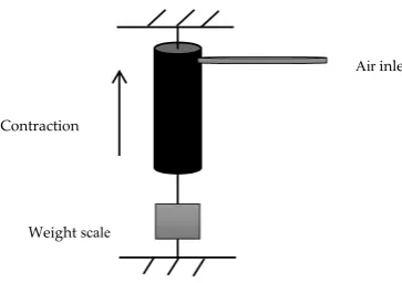
The experiment to find the expression in Equation (11) has been performed as follows:
1. An air pressure is applied to the actuator in Table 1 with step values from 0 to 5 bar. 2. At each step, the input work is calculated from Equations (3) and (8).
3. Subtracting the losses due to the stiffness and the changing in the inner area using Equation (10). 4. Calculating the output work by multiply the pulling force of the actuator by the length change
of Equation (4) (see Figure 6).
5. Repeat this experiment on different actuators.
[image:7.595.205.387.620.748.2]6. Fixed value of work losses are found to be about 0.641 Nm and it is considered to be due to the contactless losses between the inner tube and the braided sleeve, and the force losses decrease when the (∆ ) increases (i.e., the contact occurs when the pressure is increased).
Figure 6. The pulling force of the contractor PMA.
Sleeve thickness
Rubber thickness
Outer diameter Inner diameter
Braided sleeve
Rubber inner tube
Weight scale
Contraction
Air inlet Figure 5.The cross-section of the PMA structure.
The resistance force is defined as follows:
frs= sr∆Ain
L (10)
wherefrsis the resistance force (N) of the rubber tube,sr is the stiffness (N/m) of the rubber tube,
Ain(m2) is the inner area of the rubber cross-section, and∆L(m) is the change of the actuator length
between the initial length and length at each pressure step.
The losses force due to a contactless between the surfaces of the rubber tube and the braided sleeve is found experimentally as shown in Equation (11):
fc= 0.641∆
L (11)
The experiment to find the expression in Equation (11) has been performed as follows:
1. An air pressure is applied to the actuator in Table1with step values from 0 to 5 bar. 2. At each step, the input work is calculated from Equations (3) and (8).
3. Subtracting the losses due to the stiffness and the changing in the inner area using Equation (10). 4. Calculating the output work by multiply the pulling force of the actuator by the length change of
Equation (4) (see Figure6).
5. Repeat this experiment on different actuators.
6. Fixed value of work losses are found to be about 0.641 Nm and it is considered to be due to the contactless losses between the inner tube and the braided sleeve, and the force losses decrease when the (∆L) increases (i.e., the contact occurs when the pressure is increased).
Actuators 2017, 6, 32 6 of 15
Figure 5. The cross-section of the PMA structure.
The resistance force is defined as follows:
=
∆ (10)
where frs is the resistance force (N) of the rubber tube, sr is the stiffness (N/m) of the rubber tube, Ain (m2) is the inner area of the rubber cross-section, and ΔL (m) is the change of the actuator length between the initial length and length at each pressure step.
The losses force due to a contactless between the surfaces of the rubber tube and the braided sleeve is found experimentally as shown in Equation (11):
=0.641
∆ (11)
The experiment to find the expression in Equation (11) has been performed as follows:
1. An air pressure is applied to the actuator in Table 1 with step values from 0 to 5 bar. 2. At each step, the input work is calculated from Equations (3) and (8).
3. Subtracting the losses due to the stiffness and the changing in the inner area using Equation (10). 4. Calculating the output work by multiply the pulling force of the actuator by the length change
of Equation (4) (see Figure 6).
5. Repeat this experiment on different actuators.
6. Fixed value of work losses are found to be about 0.641 Nm and it is considered to be due to the contactless losses between the inner tube and the braided sleeve, and the force losses decrease when the (∆ ) increases (i.e., the contact occurs when the pressure is increased).
Figure 6. The pulling force of the contractor PMA.
Sleeve thickness
Rubber thickness
Outer diameter Inner diameter
Braided sleeve
Rubber inner tube
Weight scale Contraction
Air inlet
Under the principle of virtual work, the pulling forceFcan be defined as follows:
F= Pg∆V
∆L −frs−fc (12)
where∆Vrepresents the volume change between the initial and new value each time the pressure is changed.
To validate this equation, a 20 cm contraction actuator has been built to the specifications shown in Table1.
Table 1.The initial specifications of a 20 cm contraction PMA.
L0(m) Rubber Thickness (m) Braided Thickness (m) Inner Diameter (m) Rubber Stiffness (N/m)
0.2 1.1×10⁻³ 0.5×10⁻³ 12×10−3 363.33
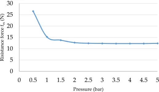
The actuator is pressurised from zero to 5 bar by 0.5 bar steps; at each step, the length of the PMA is recorded. From Equation (10), the resistance force of the inner rubber tube is illustrated in Figure7, as a function of the input pressure.
Figure7shows that the resistance force is very high at low-pressure values (Pg< 0.5 bar) and its
value has been decreased dramatically atPg= 0.5 bar.
The contactless losses at each air pressure step are also calculated and are illustrated against the pressure in Figure8. The friction value atPg< 0.5 bar is significantly high.
Actuators 2017, 6, 32 7 of 15
Under the principle of virtual work, the pulling force F can be defined as follows:
= ∆
∆ − − (12)
where ΔV represents the volume change between the initial and new value each time the pressure is
changed.
To validate this equation, a 20 cm contraction actuator has been built to the specifications shown in Table 1.
Table 1. The initial specifications of a 20 cm contraction PMA.
L0 (m) Rubber Thickness (m) Braided Thickness (m) Inner Diameter (m) Rubber Stiffness (N/m)
0.2 1.1 × 10⁻³ 0.5 × 10⁻³ 12 × 10−3 363.33
The actuator is pressurised from zero to 5 bar by 0.5 bar steps; at each step, the length of the PMA is recorded. From Equation (10), the resistance force of the inner rubber tube is illustrated in Figure 7, as a function of the input pressure.
Figure 7 shows that the resistance force is very high at low-pressure values (Pg < 0.5 bar) and its
value has been decreased dramatically at Pg = 0.5 bar.
The contactless losses at each air pressure step are also calculated and are illustrated against the
pressure in Figure 8. The friction value at Pg < 0.5 bar is significantly high.
Figure 7. The resistance force of the rubber tube against air.
Figure 8. The contactless losses between the rubber tube and the braided sleeve against air pressure.
Figure 9 shows the force of both the experimental and theoretical pulling force and it is explained that there is a substantial matching between them.
0 5 10 15 20 25 30
0 0.5 1 1.5 2 2.5 3 3.5 4 4.5 5
Resista n ce fo rc e frs (N ) Pressure (bar) 0 40 80 120 160 200 240
0 0.5 1 1.5 2 2.5 3 3.5 4 4.5 5
Co nta ct less lo sses f c (N ) Pressure (bar)
Figure 7.The resistance force of the rubber tube against air.
Actuators 2017, 6, 32 7 of 15
Under the principle of virtual work, the pulling force F can be defined as follows:
= ∆
∆ − − (12)
where ΔV represents the volume change between the initial and new value each time the pressure is
changed.
To validate this equation, a 20 cm contraction actuator has been built to the specifications shown in Table 1.
Table 1. The initial specifications of a 20 cm contraction PMA.
L0 (m) Rubber Thickness (m) Braided Thickness (m) Inner Diameter (m) Rubber Stiffness (N/m)
0.2 1.1 × 10⁻³ 0.5 × 10⁻³ 12 × 10−3 363.33
The actuator is pressurised from zero to 5 bar by 0.5 bar steps; at each step, the length of the PMA is recorded. From Equation (10), the resistance force of the inner rubber tube is illustrated in Figure 7, as a function of the input pressure.
Figure 7 shows that the resistance force is very high at low-pressure values (Pg < 0.5 bar) and its
value has been decreased dramatically at Pg = 0.5 bar.
The contactless losses at each air pressure step are also calculated and are illustrated against the
pressure in Figure 8. The friction value at Pg < 0.5 bar is significantly high.
Figure 7. The resistance force of the rubber tube against air.
Figure 8. The contactless losses between the rubber tube and the braided sleeve against air pressure.
Figure 9 shows the force of both the experimental and theoretical pulling force and it is explained that there is a substantial matching between them.
0 5 10 15 20 25 30
0 0.5 1 1.5 2 2.5 3 3.5 4 4.5 5
Resista n ce fo rc e frs (N ) Pressure (bar) 0 40 80 120 160 200 240
0 0.5 1 1.5 2 2.5 3 3.5 4 4.5 5
Co nta ct less lo sses f c (N ) Pressure (bar)
Figure 8.The contactless losses between the rubber tube and the braided sleeve against air pressure.
Actuators2017,6, 32 8 of 15
Actuators 2017, 6, 32 8 of 15
Figure 9. The experimental and theoretical force of the PMA against air pressure.
Since the value of frs and fc is high at Pg < 0.5 bar, the pulling force F cannot be produced and the
generated force increases when the opposing forces are decreased.
To ensure that the Equation (12) can fit for all contraction actuators, another actuator for the specification in Table 2 is constructed.
Table 2. The initial specifications of a high stiffness, 20 cm.
L0 (m) Rubber Thickness (m) Braided Thickness (m) Inner Diameter (m) Rubber Stiffness (N/m)
0.2 2.2 × 10⁻³ 0.5 × 10⁻³ 12 × 10−3 1090
The contactless losses (fc) for this muscle have the same values as the pressure seen in Figure 8,
while the resistance force (frs) is different because it is dependent on the rubber’s stiffness. Figure 10
shows the resistance force against the air pressure. The force of this actuator is higher than the force of the first PMA while the losses are increased because the stiffness is increased.
Increasing the stiffness of the rubber leads to increasing the resistive force, on the other hand, it
decreases the contraction ratio (ε) and, as a result, the input work will be higher.
Figure 10. The resistance force of the high stiffness rubber tube against air pressure.
The two PMAs above are made from the same rubber tube diameter, but with different stiffness values. Therefore, to further verification, an actuator is made to the specifications listed in Table 3.
Table 3. The initial specifications of the new contraction PMA.
L0 (m) Rubber Thickness (m) Braided Thickness (m) Inner Diameter (m) Rubber Stiffness (N/m)
0.2 1.1 × 10⁻³ 0.5 × 10⁻³ 26.5 × 10⁻³ 545
0 50 100 150 200 250 300 350
0 0.5 1 1.5 2 2.5 3 3.5 4 4.5 5
Force (N) Pressure (bar) experimental force theoretical force 0 10 20 30 40 50 60 70 80
0 0.5 1 1.5 2 2.5 3 3.5 4 4.5 5
Resista n ce fo rc e frs (N ) Pressure (bar)
Figure 9.The experimental and theoretical force of the PMA against air pressure.
Since the value of frsand fcis high atPg< 0.5 bar, the pulling force F cannot be produced and the
generated force increases when the opposing forces are decreased.
To ensure that the Equation (12) can fit for all contraction actuators, another actuator for the specification in Table2is constructed.
Table 2.The initial specifications of a high stiffness, 20 cm.
L0(m) Rubber Thickness (m) Braided Thickness (m) Inner Diameter (m) Rubber Stiffness (N/m)
0.2 2.2×10⁻³ 0.5×10⁻³ 12×10−3 1090
The contactless losses (fc) for this muscle have the same values as the pressure seen in
Figure8, while the resistance force (frs) is different because it is dependent on the rubber’s stiffness.
Figure10shows the resistance force against the air pressure. The force of this actuator is higher than the force of the first PMA while the losses are increased because the stiffness is increased.
Increasing the stiffness of the rubber leads to increasing the resistive force, on the other hand, it decreases the contraction ratio (ε) and, as a result, the input work will be higher.
Actuators 2017, 6, 32 8 of 15
Figure 9. The experimental and theoretical force of the PMA against air pressure.
Since the value of frs and fc is high at Pg < 0.5 bar, the pulling force F cannot be produced and the
generated force increases when the opposing forces are decreased.
To ensure that the Equation (12) can fit for all contraction actuators, another actuator for the specification in Table 2 is constructed.
Table 2. The initial specifications of a high stiffness, 20 cm.
L0 (m) Rubber Thickness (m) Braided Thickness (m) Inner Diameter (m) Rubber Stiffness (N/m)
0.2 2.2 × 10⁻³ 0.5 × 10⁻³ 12 × 10−3 1090
The contactless losses (fc) for this muscle have the same values as the pressure seen in Figure 8,
while the resistance force (frs) is different because it is dependent on the rubber’s stiffness. Figure 10
shows the resistance force against the air pressure. The force of this actuator is higher than the force of the first PMA while the losses are increased because the stiffness is increased.
Increasing the stiffness of the rubber leads to increasing the resistive force, on the other hand, it
decreases the contraction ratio (ε) and, as a result, the input work will be higher.
Figure 10. The resistance force of the high stiffness rubber tube against air pressure.
The two PMAs above are made from the same rubber tube diameter, but with different stiffness values. Therefore, to further verification, an actuator is made to the specifications listed in Table 3.
Table 3. The initial specifications of the new contraction PMA.
L0 (m) Rubber Thickness (m) Braided Thickness (m) Inner Diameter (m) Rubber Stiffness (N/m)
0.2 1.1 × 10⁻³ 0.5 × 10⁻³ 26.5 × 10⁻³ 545
0 50 100 150 200 250 300 350
0 0.5 1 1.5 2 2.5 3 3.5 4 4.5 5
Force (N) Pressure (bar) experimental force theoretical force 0 10 20 30 40 50 60 70 80
0 0.5 1 1.5 2 2.5 3 3.5 4 4.5 5
Resista n ce fo rc e frs (N ) Pressure (bar)
Figure 10.The resistance force of the high stiffness rubber tube against air pressure.
The two PMAs above are made from the same rubber tube diameter, but with different stiffness values. Therefore, to further verification, an actuator is made to the specifications listed in Table3.
Table 3.The initial specifications of the new contraction PMA.
L0(m) Rubber Thickness (m) Braided Thickness (m) Inner Diameter (m) Rubber Stiffness (N/m)
The reduced forces due to contactless losses have almost the same values because the material types are the same for both the rubber and the sleeve, whereas the resistance force is different because of the differences in diameter and stiffness of the actuators. From Equation (10) thefrscan be given
as in Figure11. The mean square error (MSE) is listed in Table4and gives the error between the experimental and the proposed force formula to the actuators understudy for the pressure steps from 0 to 0.5 bar and it is calculated according to Equation (13):
MSE= 1
k
k
∑
0
e2 (13)
wherekis the sample numbers andeis the error between the experimental and the theoretical values.
Table 4.The MSE of the three actuators.
Actuator MSE
1 7.23
2 9.31
3 22.68
Figure9and the Table4verify that the proposed force formula in Equation (12) can be used for a variety of actuators, which differ in rubber stiffness and inner diameter.
Actuators 2017, 6, 32 9 of 15
The reduced forces due to contactless losses have almost the same values because the material types are the same for both the rubber and the sleeve, whereas the resistance force is different because
of the differences in diameter and stiffness of the actuators. From Equation (10) the frs can be given as
in Figure 11. The mean square error (MSE) is listed in Table 4 and gives the error between the experimental and the proposed force formula to the actuators understudy for the pressure steps from 0 to 0.5 bar and it is calculated according to Equation (13):
=1 (13)
where k is the sample numbers and e is the error between the experimental and the theoretical values.
Table 4. The MSE of the three actuators.
Actuator MSE
1 7.23 2 9.31 3 22.68
[image:10.595.167.426.372.523.2] [image:10.595.77.403.666.778.2]Figure 9 and the Table 4 verify that the proposed force formula in Equation (12) can be used for a variety of actuators, which differ in rubber stiffness and inner diameter.
Figure 11. The resistance force of the third actuator against air pressure.
5. Structure-Based Length Formula for Contraction PMAs
The length of the contraction PMA decreases, while the applied pressure is raised. However, the
contraction ratio (ε) is not fixed for all actuators and it depends on the type of inner rubber tube, the
diameter of the PMA, and the maximum diameter of the braided sleeve. Al-Ibadi, et al. [12] proposed a length formula as in Equation (14).
Their formula is derived for a range of actuator lengths, from 0.15 m to 0.4 m. Furthermore, similar rubber tube and actuator diameters have been used:
= +
[1 + ( ) ]
− 0.009 (14)
where: =
0.4351 0 0.0183 −0.0003 0.5649
−0.0141 0.5487
0
0 −0.0183 0.0003 0 0.0031 −0.00006 0 −0.0136 0.00007
0.3694 0 0
. 0 5 10 15 20 25 30
0 0.5 1 1.5 2 2.5 3 3.5 4 4.5 5
Risista n ce fo rc e frs (N ) Pressure (bar)
Figure 11.The resistance force of the third actuator against air pressure.
5. Structure-Based Length Formula for Contraction PMAs
The length of the contraction PMA decreases, while the applied pressure is raised. However, the contraction ratio (ε) is not fixed for all actuators and it depends on the type of inner rubber tube, the diameter of the PMA, and the maximum diameter of the braided sleeve. Al-Ibadi, et al. [12] proposed a length formula as in Equation (14).
Their formula is derived for a range of actuator lengths, from 0.15 m to 0.4 m. Furthermore, similar rubber tube and actuator diameters have been used:
L=a+ b
[1+ (Pcg)d]
e −0.009L0
q
Pg (14)
where: a b c d e =
0.4351 0 0.0183 −0.0003
0.5649 0 −0.0183 0.0003
−0.0141 0 0.0031 −0.00006
0.5487 0 −0.0136 0.00007
0 0.3694 0 0
L0 L−00.248
L2 0 L30
Actuators2017,6, 32 10 of 15
where: the parametersa,b,c,d, andeare constants for eachL0and they represent the coefficients of Equation (14).
To present an efficient length formula that is able to track the actual length of the PMA, the initial length (L0), initial diameter (D0), and the rubber stiffness must be considered. While the contraction ratio increases as a pressure increase, and the highest rubber stiffnesssrleads to the lowest stretchable
ability, then:
Lα 1
Pg (15)
Lα 1
sr (16)
and to avoid dividing by zero, an exponential form will be considered as follows:
L=L0− aL0
(1+e−bDosr Pg)6.214
(17)
whereaandbare constants for a fixed structure and the expression to find them depends on the diameter and stiffness of the PMA.
"
a b
#
=
"
0.0126 14882 −2 ×10⁸
2×10⁻⁵ −0.5375 11777
#
1
D
0
sr
D2 0
s2
r
(18)
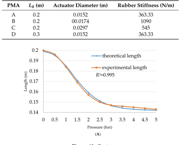
[image:11.595.177.427.336.388.2]To improve the efficiency of this equation, four actuators are made to the specifications listed in Table5and Figure12illustrates the theoretical and the experimental data according to Equation (17).
Table 5.The specifications of the contraction PMAs.
PMA L0(m) Actuator Diameter (m) Rubber Stiffness (N/m)
A 0.2 0.0152 363.33
B 0.2 00.0174 1090
C 0.2 0.0297 545
D 0.3 0.0152 363.33
Actuators 2017, 6, 32 10 of 15 where: the parameters a, b, c, d, and e are constants for each L0 and they represent the coefficients of Equation (14).
To present an efficient length formula that is able to track the actual length of the PMA, the initial length (L0), initial diameter (D0), and the rubber stiffness must be considered. While the contraction ratio increases as a pressure increase, and the highest rubber stiffness srleads to the lowest stretchable ability, then:
1
(15)
1
(16)
and to avoid dividing by zero, an exponential form will be considered as follows:
= −
(1 + ). (17)
where a and b are constants for a fixed structure and the expression to find them depends on the diameter and stiffness of the PMA.
= 0.0126 14882 −2 × 10
2 × 10 −0.5375 11777
1
(18)
To improve the efficiency of this equation, four actuators are made to the specifications listed in Table 5 and Figure 12 illustrates the theoretical and the experimental data according to equation (17).
Table 5. The specifications of the contraction PMAs.
PMA L0 (m) Actuator Diameter (m) Rubber Stiffness (N/m)
A 0.2 0.0152 363.33
B 0.2 00.0174 1090
C 0.2 0.0297 545
D 0.3 0.0152 363.33
0.14 0.15 0.16 0.17 0.18 0.19 0.2
0 0.5 1 1.5 2 2.5 3 3.5 4 4.5 5
Length (m)
Pressure (bar)
theoretical length
experimental length
(A)
[image:11.595.145.449.455.700.2]R2=0.995
Actuators 2017, 6, 32 11 of 15
Figure 12. The experimental and theoretical length of the PMAs. (A–D) represent the length for the PMAs in Table 5 respectively.
While the experimental length is recorded as an average for the length during contraction and elongation, the small deviation remains inside the whole curve.
As an example, Figure 13 shows the length of the actuator B with a contraction and elongation curve.
The length formula in Equation (17) can be used in Equation (12) at any air pressure value to detect the contractor force. Furthermore, the position of a single actuator can be defined at any time for all PMAs under their structure specification.
0.16 0.17 0.18 0.19 0.2
0 0.5 1 1.5 2 2.5 3 3.5 4 4.5 5
Length (m)
pressure (bar)
theoretical length
experimental length
(B)
0.15 0.16 0.17 0.18 0.19 0.2
0 0.5 1 1.5 2 2.5 3 3.5 4 4.5 5
Length (m)
Pressure (bar)
theoretical length
experimental length
(C)
0.2 0.22 0.24 0.26 0.28 0.3
0 0.5 1 1.5 2 2.5 3 3.5 4 4.5 5
Length (m)
Pressure (bar)
theoretical length
experimental length
(D)
R2=0.997
R2=0.993
R2=0.997
Figure 12.The experimental and theoretical length of the PMAs. (A–D) represent the length for the PMAs in Table5respectively.
While the experimental length is recorded as an average for the length during contraction and elongation, the small deviation remains inside the whole curve.
As an example, Figure 13 shows the length of the actuator B with a contraction and elongation curve.
The length formula in Equation (17) can be used in Equation (12) at any air pressure value to detect the contractor force. Furthermore, the position of a single actuator can be defined at any time for all PMAs under their structure specification.
Actuators2017,6, 32 12 of 15
Actuators 2017, 6, 32 12 of 15
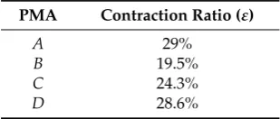
Sárosi, et al. [19] argue that the maximum contraction ratio is about 25%. However, from Equation (17), and as illustrated in Figure 12, the contraction ratio depends on the stiffness and
diameter of the actuator and is not fixed. Table 6 lists the contraction ratio of the actuators (A, B, C,
[image:13.595.146.450.89.276.2]and D), which are according to the specifications given in Table 5.
[image:13.595.220.375.335.401.2]Figure 13. The length of the actuator B with the contraction and elongation curve.
Table 6. The contraction ratio of the PMAs.
PMA Contraction Ratio (ε)
A 29%
B 19.5%
C 24.3%
D 28.6%
Table 6 shows that the contraction ratio has an inverse relationship with the stiffness of the inner
rubber tube, where both A and D actuators have similar values of the contraction ration, while it
decreased for the actuator C, whereas actuator B has the minimum contraction ratio (see Table 5).
[image:13.595.238.358.529.618.2]Since Equation (17) is derived from fitting the length of the actuator at no-load, Table 7 lists the MSE at different load values for the 20 cm contraction PMA, fit for centimetres, for 11 steps of pressure from 0 to 0.5 bar.
Table 7. The MSE of the 20 cm contraction PMA at different loads.
Load (kg) MSE
0.0 0.01982 0.5 0.1405 1.0 0.1995 2.0 0.2363 3.0 0.431 4.0 0.9697
6. The Stiffness of the Contraction PMA
One of the major advantages of the PMA is the variable stiffness performance [20] where the stiffness of this type of actuator is changing with the applied pressure. The stiffness is defined as the length change due to changes in the applied force.
From Equations (12) and (17) the stiffness can be defined as in Equation (19): 0.16
0.165 0.17 0.175 0.18 0.185 0.19 0.195 0.2
0 0.5 1 1.5 2 2.5 3 3.5 4 4.5 5
Length (m)
Pressure (bar)
theoretical average length
experimental average length
length during contraction and elongation
R2=0.993
Figure 13.The length of the actuatorBwith the contraction and elongation curve.
Table 6.The contraction ratio of the PMAs.
PMA Contraction Ratio (ε)
A 29%
B 19.5%
C 24.3%
D 28.6%
Table6shows that the contraction ratio has an inverse relationship with the stiffness of the inner rubber tube, where bothAandDactuators have similar values of the contraction ration, while it decreased for the actuatorC, whereas actuatorBhas the minimum contraction ratio (see Table5).
Since Equation (17) is derived from fitting the length of the actuator at no-load, Table7lists the MSE at different load values for the 20 cm contraction PMA, fit for centimetres, for 11 steps of pressure from 0 to 0.5 bar.
Table 7.The MSE of the 20 cm contraction PMA at different loads.
Load (kg) MSE
0.0 0.01982
0.5 0.1405
1.0 0.1995
2.0 0.2363
3.0 0.431
4.0 0.9697
6. The Stiffness of the Contraction PMA
One of the major advantages of the PMA is the variable stiffness performance [20] where the stiffness of this type of actuator is changing with the applied pressure. The stiffness is defined as the length change due to changes in the applied force.
From Equations (12) and (17) the stiffness can be defined as in Equation (19):
s= Pg∆V ∆L2 −
frs
∆L− fr
∆L (19)
Actuators2017,6, 32 13 of 15
the stiffness for the actuators (A,B, andC) in Table5as a function of air pressure. The stiffness of actuatorDis similar to the stiffness of actuatorAbecause it has the same material specifications and contraction ratio.
= ∆
∆ −∆ −∆ (19)
While both the length and the force of the actuator depending on the structure of the PMA, the stiffness (s) is determined by the structure of the PMA, correspondingly. Figure 14 above describes the stiffness for the actuators (A, B, and C) in Table 5 as a function of air pressure. The stiffness of actuator D is similar to the stiffness of actuator A because it has the same material specifications and contraction ratio.
0 1,000 2,000 3,000 4,000 5,000 6,000
0 0.5 1 1.5 2 2.5 3 3.5 4 4.5 5
Stiffness (N
/m
)
pressure (bar)
experimental stiffness
theoretical stiffness
(A)
0 2,000 4,000 6,000 8,000 10,000
0 0.5 1 1.5 2 2.5 3 3.5 4 4.5 5
Stiffness (N
/m
)
Pressure (bar)
experimental stiffness
theoretical stiffness
(B)
0 2,000 4,000 6,000 8,000 10,000 12,000
0 0.5 1 1.5 2 2.5 3 3.5 4 4.5 5
Stiffness (N
/m
)
Pressure (bar)
experimental stiffness
theoretical stiffness
(C) R2=0.998
R2=0.998
[image:14.595.165.431.137.588.2]R2=0.999
Figure 14.The experimental and theoretical stiffness of the three different PMAs. (A–C) represent the stiffness for the PMAs in Table5respectively.
7. Conclusions
Modelling the nonlinear system, such as that of the pneumatic muscle actuator (PMA) is a challenge and has three major performances; contraction, pulling force, and variable stiffness. An efficient model must describe the full mechanical behaviour. Since the McKibben artificial muscle is applicable for structure differences, the most effective model has to be based on the structure coefficients, such as initial length, initial inner diameter, the thickness of both the inner rubber tube and the braided sleeve and the stiffness of the rubber tube or, in other words, its ability to extend.
Actuators2017,6, 32 14 of 15
show that this model might be considered a general force formula to the contraction PMA, whatever the structure. On the other hand, it overcame two of the previous assumptions: the zero wall thickness, and ignoring the friction. These have a significant impact on the actuator force, especially at low air pressure values.
The contraction length formula has been generalised in this paper in comparison with the previous work in [12], which depended on the initial actuator length for similar inner tube performances. The new formula is validated to different contraction actuators and it has been formulated to fit various constructions. The proposed actuator length formula has been derived from the no-load condition, then, it is validated to different load values.
A general stiffness formula for the contraction PMA has been defined and verified for the PMAs under study. The result has proved the effectiveness of the structure on the PMA stiffness.
These models cause the control of force, contraction length (end position) and the stiffness to easily and clearly describe the behaviour of the contraction PMAs under pressurised conditions, which helps in choosing a suitable structure for the required application.
As a future project, a suitable structure will be selected to design and build an efficient continuum arm for different applications, as well as design the proper control system which depends on the muscle parameters.
Acknowledgments: The authors would like to thank the Ministry of Higher Education (Iraq), University of Basrah, Computer-Engineering Department for providing scholarship support to the first author of this paper.
Author Contributions:Alaa Al-Ibadi designed and performed the experiments; Al-Ibadi and Davis analysed the data; Al-Ibadi wrote the paper; and Samia Nefti-Meziani edited the paper.
Conflicts of Interest:The authors declare no conflict of interest.
References
1. Bicchi, A.; Tonietti, G.; Bavaro, M.; Piccigallo, M. Variable stiffness actuators for fast and safe motion control. InRobotics Research—The Eleventh International Symposium, Springer Tracts in Advanced Robotics; Springer: Berlin/Heidelberg, Germany, 2005; Volume 15, pp. 527–536.
2. Tonietti, G.; Schiavi, R.; Bicchi, A. Design and control of a variable stiffness actuator for safe and fast physical human/robot interaction. In Proceedings of the 2005 IEEE International Conference on Robotics and Automation (ICRA), Barcelona, Spain, 18–22 April 2005; pp. 526–531.
3. Schiavi, R.; Grioli, G.; Sen, S.; Bicchi, A. VSA-II: A novel prototype of variable stiffness actuator for safe and performing robots interacting with humans. In Proceedings of the 2008 IEEE International Conference on Robotics and Automation (ICRA), Pasadena, CA, USA, 19–23 May 2008; pp. 2171–2176.
4. Bartow, A.; Kapadia, A.; Walker, I. A novel continuum trunk robot based on contractor muscles. In Proceedings of the 12th WSEAS International Conference on Signal, Processing, Robotics, and Automation, Cambridge, UK, 20–22 Febuary 2013; pp. 181–186.
5. McMahan, W.; Jones, B.A.; Walker, I.D. Design and implementation of a multi-section continuum robot: Air-Octor. In Proceedings of the 2005 IEEE/RSJ International Conference on Intelligent Robots and Systems, (IROS 2005), Edmonton, AB, Canada, 2–6 August 2005; pp. 2578–2585.
6. Mazzolai, B.; Margheri, L.; Cianchetti, M.; Dario, P.; Laschi, C. Soft-robotic arm inspired by the octopus: II. From artificial requirements to innovative technological solutions. Bioinspir. Biomim. 2012,7, 025005. [CrossRef] [PubMed]
7. Aun, K.K.; Anh, H.P.H. System modeling identification and control of the two-link pneumatic artificial muscle manipulator optimized with genetic algorithms. In Proceedings of the 2007 IEEE International Conference on Control and Automation (ICCA), Guangzhou, China, 30 May–1 June 2007; pp. 501–506. 8. Walker, I.D. Continuous backbone “continuum” robot manipulators.ISRN Robot.2013,2013. [CrossRef] 9. Tondu, B.; Lopez, P. Modeling and control of McKibben artificial muscle robot actuators.IEEE Control Syst.
2000,20, 15–38. [CrossRef]
11. Chou, C.-P.; Hannaford, B. Measurement and modeling of McKibben pneumatic artificial muscles.IEEE Trans. Robot. Autom.1996,12, 90–102. [CrossRef]
12. Al-Ibadi, A.; Nefti-Meziani, S.; Davis, S. Valuable experimental model of contraction pneumatic muscle actuator. Proceeding of the 2016 21st IEEE International Conference on Methods and Models in Automation and Robotics (MMAR), Miedzyzdroje, Poland, 29 August–1 September 2016; pp. 744–749.
13. Aschemann, H.; Schindele, D. Comparison of model-based approaches to the compensation of hysteresis in the force characteristic of pneumatic muscles.IEEE Trans. Ind. Electron.2014,61, 3620–3629.
14. Wickramatunge, K.C.; Leephakpreeda, T. Study on mechanical behaviors of pneumatic artificial muscle. Int. J. Eng. Sci.2010,48, 188–198. [CrossRef]
15. Tondu, B. Modelling of the McKibben artificial muscle: A review. J. Intell. Mater. Syst. Struct. 2012, 23, 225–253. [CrossRef]
16. Kelasidi, E.; Andrikopoulos, G.; Nikolakopoulos, G.; Manesis, S. A survey on pneumatic muscle actuators modeling. In Proceedings of the 2011 IEEE International Symposium on Industrial Electronics (ISIE), Gdansk, Poland, 27–30 June 2011; pp. 1263–1269.
17. Tatlicioglu, E.; Walker, I.D.; Dawson, D.M. Dynamic modelling for planar extensible continuum robot manipulators. In Proceedings of the 2007 IEEE International Conference on Robotics and Automation, Roma, Italy, 10–14 April 2007; pp. 1357–1362.
18. Kang, B.-S.; Kothera, C.S.; Woods, B.K.; Wereley, N.M. Dynamic modeling of Mckibben pneumatic artificial muscles for antagonistic actuation. In Proceedings of the 2009 IEEE International Conference on Robotics and Automation (ICRA’09), Kobe, Japan, 12–17 May 2009; pp. 182–187.
19. Sárosi, J.; Bíró, I.; Németh, J.; Cveticanin, L. Dynamic modeling of a pneumatic muscle actuator with two-direction motion.Mech. Mach. Theory2015,85, 25–34. [CrossRef]
20. Vanderborght, B.; Albu-Schäffer, A.; Bicchi, A.; Burdet, E.; Caldwell, D.G.; Carloni, R.; Catalano, M.; Eiberger, O.; Friedl, W.; Ganesh, G.; et al. Variable impedance actuators: A review.Robot. Auton. Syst.2013, 61, 1601–1614. [CrossRef]