doi:10.4236/cn.2013.52B007 Published Online May 2013 (http://www.scirp.org/journal/cn)
RSSI-based Algorithm for Indoor Localization
Xiuyan Zhu, Yuan Feng*
College of Information Science and Engineering, Ocean University of China, Qingdao, China Email: *[email protected]
Received 2013
ABSTRACT
Wireless node localization is one of the key technologies for wireless sensor networks. Outdoor localization can use GPS, AGPS (Assisted Global Positioning System) [6], but in buildings like supermarkets and underground parking, the accuracy of GPS and even AGPS will be greatly reduced. Since Indoor localization requests higher accuracy, using GPS or AGPS for indoor localization is not feasible in the current view. RSSI-based trilateral localization algorithm, due to its low cost, no additional hardware support, and easy-understanding, it becomes the mainstream localization algorithm in wireless sensor networks. With the development of wireless sensor networks and smart devices, the num-ber of WIFI access point in these buildings is increasing, as long as a mobile smart device can detect three or three more known WIFI hotspots’ positions, it would be relatively easy to realize self-localization (Usually WIFI access points locations are fixed). The key problem is that the RSSI value is relatively vulnerable to the influence of the physical en-vironment, causing large calculation error in RSSI-based localization algorithm. The paper proposes an improved RSSI-based algorithm, the experimental results show that compared with original RSSI-based localization algorithms the algorithm improves the localization accuracy and reduces the deviation.
Keywords: Indoor Localization Algorithm; RSSI-based; WIFI Access Point; Smart Phones
1. Introduction
More than 80% information is related to spatial location, and modern people spend about 80% - 90% time of their whole life indoors. Now along with the popularization of information and communication technology, people’s demands for indoor location information are growing. In some public places, such as shopping malls, airports, exhibition halls, office buildings, warehouses, under- ground parking, prisons, military training bases, people need precise location information. Precise indoor loca- tion information can be used to achieve efficient man- agement of the available space and inventory substances; can help police, firefighters, soldiers, medical staff to complete specific tasks; smart spaces and pervasive computing are also inseparable from the location-based services. So currently, indoor localization is a hot re- search with broad application prospects [9].
Compared with outdoor localization, the difficulty of indoor localization lies in that indoor maps pay more attention to small areas, large-scale, high precision and subtly display of the internal elements [7].
Along with the rapid development of wireless net- works and smart phones, the number of WIFI access points increase dramatically and most WIFI access points’ locations are fixed. This phenomenon suggests a
new direction for indoor localization research in wireless sensor network.
Existing wireless localization algorithms require either special hardware support or complex computing, which consuming valuable battery resources greatly, especially comes to smart phones or sensors. The contribution of this paper is that it proposed a new algorithm,which increase the indoor localization accuracy without any additional hardware support or increasing the computa- tional complexity.
2. Related Work
2.1. Indoor Localization Technologies
There are many wireless localization technologies and solutions. The commonly used localization techniques include infrared, ultrasonic, radio frequency signal, Blue- tooth, and Ultra-Wideband, WIFI, etc.[8], but they are not suitable for indoor localization. Infrared is only suit-able for short-distance transmission, and could easily be influenced by fluorescent lamp or the light in the room, there are limitations on the localization accuracy; ultra-sonic, Bluetooth and Ultra-Wideband require special equipment, the cost is too high, hence they are not widely used; RF signal does not have communication capability, and is not easy to be integrated into other systems.
are open and free. The most widely used localization technology is using WIFI.
2.2. Localization Algorithms
Wireless localization algorithms can be roughly divided into two categories[2], Range-based and Range-free lo-calization algorithms.
Range-based localization algorithms mainly include RSSI-based trilateral localization algorithm, arrival angle algorithm (AOA), arrival time algorithm (TOA) and time difference of arrival (TDOA) algorithm. TOA requires precise clock synchronization; TDOA node is equipped with ultrasonic transmitters and receivers; AOA needs antenna array or microphone arrays. These three algo-rithms’ localization accuracy is high, however with high hardware requirements.
Range-free localization algorithm mainly includes centroid algorithm, DV-hop algorithm, MDS-MAP algo-rithm and convex programming. Range-free algoalgo-rithms mainly use the geometric relationship between neighbor-ing nodes to estimate localization. They have low hard-ware requirements, but the localization accuracy is too low for indoor environment.
Because of its simple, easy-understanding and low cost, RSSI-based trilateral localization algorithm has a wide range of applications.
3. Trilateral Localization Algorithm
3.1. Wireless Signal Propagation Loss Models
In this paper we use the mainstream logarithmic distance path loss model, i.e., log model. The propagation model
points out that whether in indoor or outdoor channel, the average received signal power decreases with the loga-rithm of distance. This model has been widely used. For any T-R distance, the path loss is expressed as:
0 1, 2,...,
i i d L d P i d η
n
(1) or
0 100
10 log di ( 1, 2,..., )
PL dB PL d i n
d
(2)
In the above formula, 0 represents near earth refer-ence distance,
d
0PL d is the signal strength at distance
0 and
d is the signal attenuation factor and its value is between 2 to 6 in different environments.
3.2. Trilateral Localization
Assume there are n anchor nodes, and the location of the
unknown node is ( , )x y , i' is the estimated distance between the unknown node and the anchor node
d
i th
( , )x yi i obtained by using the log-model and
repre-sents the real distance. Then
i
d
' 2 2
0 0
( ) ( ) ( 1, 2,...
i i i
d x x y y i n) (3) The difference between the real distance and the esti-mated distance is expressed as '
i di di
. Because of inevitable error, i cannot be zero, the solution of
ac-quiring the best estimated location is to use the least squares algorithm to make 2
1 n i i
minimum. From (3) we can get n formulas as follows:
2 2 2 2 2
0 0 0 0
2 2
( 1, 2,... )
i i i i i
x y d x x y y x y
i n
(4)
Use the prior n-1 formulas minus the formula
respectively; we can get n-1 new formulas:
nth
2 2 2 2 2
0 0
2 ( )
2 ( )
i n n i n
i n i
i
n
y x y d d
x x x y y y
x
2
0
(5)
Let ;
2 2 2 2 2 2
1 1 1
2 2 2 2 2 2
2 2 2
2 2 2 2 2 2
1 1 1
n n n
n n n
n n n n n n
B
x y x y d d
x y x y d d
x y x y d d
0 X x y ;
1 1 2 2 1 1 2 2( 2 2( 2 2( n n n nn n n n
A
x x y y
x x y y
) )
)
x x y y
,
then we obtain the following equation:
AX b (6)
Usually i in b is unknown, but i composed of
can be estimated by the model mentioned before, so
d d'
' b 2 1 n i i min
means '2
AX
min b , then the resolution of
'
X is as follows:
' ( T ) 1 T
X A A A b' (7) The more beacon nodes there are, the higher localiza-tion accuracy we get, but the greater the cost. In real cases, three anchor nodes are enough to locate an un-known node, so we take n = 3. Figure 1 shows the trilat-eral localization algorithm.
4. The Improved Algorithm
39
4.1. Algorithm Idea
In the original RSSI-based localization algorithm, when measuring the actual RSSI values of the beacon nodes, the error caused by the obstacles (i.e., when the device
holder’s back towards the WIFI node, the device holder is the obstacle) or the antenna direction will be persis-tently substituted into the formula involved in the opera-tion, the error becomes greater with the accumulation. This is one of the main reasons of the big error in RSSI-based localization.
[1] proposes that when a device holder stands with his back towards the WIFI access point, a sharp decline of the WIFI signal appears due to the blocking of body. In the paper, mobile device owners do 6 s uniform mo-tion while collecting data once per second and one revo-lution takes one minute. But in reality, this cannot be done in all circumstances. So we use built-in gyro sensor
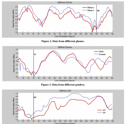
in smart phones to collect intensity value of the gyro-scope while collecting WIFI signal. The rotated angle can be obtained by calculating the gyro sensor values, so that even if our rotation is non-uniform motion, the RSSI value and the rotated angle can be recorded within a shorter time. The observed signal strength profiles with user rotation are shown in Figures 2-4:
0 1
2
3 0 2
3
1
[image:3.595.347.501.180.266.2](a) (b)
[image:3.595.87.505.302.718.2]Figure 1. Trilateration. (a) Measuring distance to 3 anchor nodes; (b) Ranging circles.
Figure 2. Data from different phones.
[image:3.595.94.501.308.428.2]Figure 3. Data from different genders.
Figure 2 shows that the signal profile displays a clear low signal artifact when a user holds different phones. In Figure 3, we repeat the above experiments using differ-ent persons, with varying heights and weights. The same artifact consistently appears. In Figure 4, with different APs, the low signal artifact still comes across clearly in measurement results. This demonstrates that the low sig-nal effect appears stably when the device holder’s back faces the WIFI AP, the RSSI values will decline. Using gyroscope saves time, breaks the restrictions of the uni-form motion, maintains the accuracy simultaneously (the average error is 5°to 15°).
In most cases, when the device holder faces the WIFI access point, the WIFI signal attenuation is minimal. If we can find the direction of facing the WIFI access point and use the RSSI value on this direction as the trilateral localization input, then the accuracy of the subsequent calculations to obtain the position will increase. [1,4,5] have proposed algorithms of looking for WIFI direction. [1] uses sliding window on the RSSI data, while [4] and [5] use RSSI gradient map. Finding WIFI access points make people get faster data transmission rate by shorten-ing the distance to WIFI point, it can also be applied to rescue tasks. Here we combine it with original trilateral localization algorithm to get higher localization accuracy. It is a simple calculation algorithm without requiring any additional hardware support. Because gradient algorithm is more complex than the sliding window algorithm and for mobile devices the battery resource is limited, we decide to use the former.
Let the mobile device holder spins around to collect tetrad
Angles RSSI RSSIj 1j 2jRSSI3j
of one circle.j
Angles stands for thejthrotation angle and
1, 2,3; 1, 2,...
ij
RSSI i j n
represents the RSSI value of the WIFI access point. Use the sliding window to process the col-lected data to obtain the facing angle
th
j ith
. In order not to increase the complexity of the algorithm, we take the average of the RSSI values in the interval
as the input of the trilateral local-ization algorithm. 1 1 n i i j ij AveRSSI RSSI n
Angles
(8)The angle error calculated is between (5 ~ 15 ) . To reduce the error as much as possible, we take β = 15.
Using formula (8) we can obtain AveRSSIi.
Respec-tively, substitute the three values into the log model and get the distances of the mobile phone to the three WIFI APs. Then use the least square algorithm mentioned in
section 3 to get the phone’s position. The experimental results prove that this algorithm can obtain higher accu-racy and less error than the original trilateral localization algorithm without any additional hardware support.
4.2. Experimental Environment Parameter Fitting
The signal propagation is susceptible to the influence of environmental factors, such that under different circum-stances, the degree of signal attenuation differs [3]. We reduce the location deviation caused by environmental factors by fitting out the initial model parameters com-plied with the current environment.
In the experiment, we took (m/km) and col-lected 20 groups of 0
1
d
; 1, 2,...20
ij
RSSI i j
( 1, 2
1, 2,...10
,...10)
at 10 different distances d ii from three routers
respectively. ij represents the RSSI value
at the
RSSI ith
th
i location, and PL
di i dstands for average signal strength at distance .
20 1( 1, 2, 10; 1, 2, 20)
i ij
j
PL d RSSI
i j
(9)
PL d
Let X 0
; 10 1 10 2 10 10
1 10 log ( )
1 10 log ( )
1 10 log ( )
d d Z d And
1 2 10 PL d PL d Y PL d ), then we can obtain the matrix
equation (10) as follows:
0
Z ( 1
Y X d (10) The problem of finding the initial value PL d
0 andattenuation factor that applies to the current envi-ronment turns into computing the value of X that satisfy
the formula (11), to minimize that the sum of the squares of the difference between the calculated function curve and the observed value, we get the following expressed as:
1 12 0 2
0
10 10
2
1 10 log( )
1 10 log( )
,
1 10 log( )
PL d d
min d PL d PL d
PL d
d PL d
[image:4.595.308.543.326.531.2]41
The solution to the formula (11) is ( T ) 1 T
X A A A b. Put X into equation (2) to gain the model that adjusts to
the current environment.
Using the above algorithm, the initial parameters for the experimental environment we get is shown in the following Table 1.
5. Algorithm Evaluation
5.1. Establish the Coordinate System
The size of the laboratory is about . Figure 5 shows the layout of the laboratory. There are three wire-less routings deployed at three non-linear different places. Take the east as the positive direction of the x-axis, and the west-north of the laboratory as the origin.
2 8*7 m( )
5.2. Experiment Results
In Table 2, AFT which represents our algorithm, means AP Faced Trilateral. It shows the statistics positioning result of traditional trilateral and AFT, including the av-erage positioning deviations and positioning deviations under the best and the worst circumstances.
Figure 6 shows the comparison of the positions calcu-lated by using the proposed algorithm and the original algorithm respectively. It can be seen that the computed positions of the improved algorithm are distributed in a circle with a radius of 1m, (3.6, -3.3) as the origin, and the computed locations of the original algorithm are more dispersed.
Figure 7 shows the error comparison that obtained in the 20 tests between the two algorithms. It can be seen that in the vast majority of cases, the improved algorithm
gained the higher accuracy than the original algorithm, and only in a particular case, the presence of the multi-path effects in signal propagation, making the algorithm failed.
Table 1. The fitting arguments for the attenuation model.
Environment PL d
0
LAB 44 3.6
Figure 5. Experiment environment topology.
Table 2. Positioning statistics.
Algorithms AFT Trilateral
Minimum deviation 0.2358 0.3528
Maximum deviation 1.5769 2.9730
Average deviation 0.8562 1.4235
Variance 0.2374 0.7808
Figure 6. The location of the unknown node computed by these two algorithms.
6. Conclusions
Although the experiment results show that the proposed algorithm in this paper raised the localization accuracy without increasing the complexity and cost, but the algo-rithm is still defective. First of all, people can only local-ize themselves where at least there are three WIFI access points around; second, the frequency of mining data can only adopt the minimum value between the gyroscope sampling rate and WIFI scan rate to ensure not collect useless data. Gyroscope is a short-time precision instru-ment, so the gyro accuracy cannot be fully utilized and cannot get more intensive WIFI access points’ data. It will be the further research direction, and if these two problems can be solved, the indoor localization accuracy can be further improved.
7. Acknowledgements
This research is partially supported by National Natural Science Foundation of China under Grant No. 60933011 and 61003238.
REFERENCES
[1] “I Am the Antenna: Accurate Outdoor AP Location using
Smartphones,” MobiCom’11, Las Vegas, Nevada, USA, 2011.
[2] Y. H. Liu, Z. Yang, X. P. Wang and L. Jian,“Location, Localization, and Localizability,” Journal Of Computer Science and Technology, Vol. 25, No. 2, 2010, pp. 274-297.doi:10.1007/s11390-010-9324-2
[3] “Perpendicular Intersection: Locating Wireless Sensors with Mobile Beacon,” Journal Of Computer Science and Technology, Vol. 25, No. 2, 2010, pp. 274-297.
[4] “GUIDE-gradient: A Guiding Algorithm for Mobile Nodes in WLAN and Ad-hoc,” Networks Wireless Pers Communications..
[5] “Access Point Localization Using Local Signal Strength Gradient,” Network Measurement, LNCS 5448, 2009, pp. 91–100.
[6] http://baike.baidu.com/view/1088042.htm
[7] http://www.navinfo.com.cn/news/detail.aspx?id=804&sor t=1
[8] L. J. Wang, L. Q. Tian and C. Hu. “Wireless location technology overview,” Advanced technology research bulletin, Vol. 4, No. 3, 2010.