5th International Scientific and Business Conference—Future Engineering 2019 ISBN: 978-1-60595-632-9
Development Works on Applying Force
Feedback in Robot Control System
Łukasz Mucha
1ABSTRACT
The article presents the design stages, the principles of operation, and the tests of the force that is exerted on the operator. It also includes the developed a laboratory stand for testing the force interactions, concepts and ways of implementing the transfer of tactile stimuli, subsequent variants of the developed devices with the short description of them, the project of the operator-surgeon stand that is based on the assumption that the method of control of this device is compatible with the natural work of the surgeon, and the project of control console that is used to manipulate the surgical robot. This paper presents the actual state of the work and further possible directions of the development of the human-machine interface which is developed within the project LIDER VIII.
Keywords: RobinHand, haptic, force feedback
INTRODUCTION
Nowadays, due to the growing demand of patients and doctors for less traumatic surgical methods, the idea of the operations performed by robots (telemanipulators) has appeared. Medical robotic systems can make surgical and rehabilitation interventions more efficient, accurate, accessible, and reliable. Thanks to that, the load of healthcare systems will be reduced. The need to introduce surgical robots to the operating rooms is caused by the current long waiting times for operations and the decreased group of specialists. The application of the robots not only increases the quality of operations, but also shortens the time of the procedure by using the advantages of the tools that are used during this operation. Medical robotic __________
1
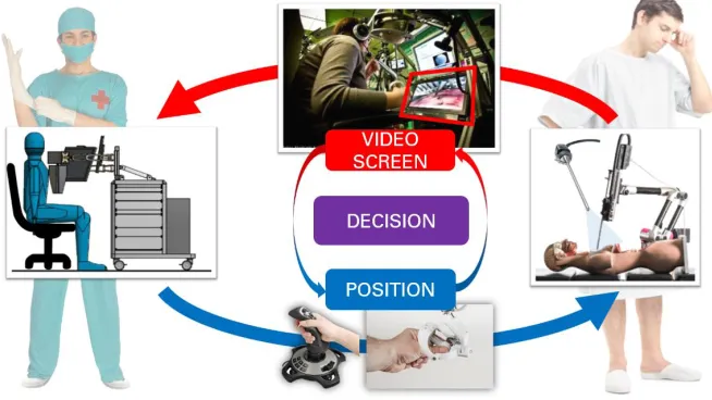
instruments are connected with instrumentations, imaging, and the verification of the tool position in real time. A schematic diagram of surgery using surgical robots is shown in Fig. 1. On the one hand, there is a surgeon with the control console. On the other hand, there is the patient and the telemanipulator. The control console is equipped with special interfaces, which is a motion controller, to manipulate the robot. The surgeon’s knowledge about the current position of the tool is needed for real time controlling. It is possible, thanks to the laparoscopic camera connected to the console monitor screen on which the operator observes the operating area. Based on the currently displayed image, the surgeon decides about the location of the laparoscopic tool inside the patient's abdominal cavity. Thanks to this solution, the surgeon can comfortably carry out surgery in a sitting position. This significantly increases his work comfort [1-5].
Figure 1. A diagram of surgery with using surgical robots.
THE IDEA OF CONTROL
The control system with the force feedback is the one of the most popular methods of controlling the telemanipulators (Fig. 2). The idea of such control procedure includes the following stages:
1. The operator observes the current position of the tool on the monitor screen and at the same time he changes the position of his hand in which he holds the end part of the motion controller.
2. Motion controller is equipped with a measuring system (encoders) that allows identification of the current position of the surgeon's hand in the space.
3. The control signal from the motion controller is transmitted to the telemanipulator, which changes the orientation of his arm by using the servomechanism.
4. Along with the movement of the telemanipulator, the position of the tool also changes, and the manipulation of additional degrees of freedom of the tool and opening or closing the effector jaws are performed.
5. The surgical instrument may be equipped with the additional sensors that allow one to measure the force value. The force measurement can be also done on the robot arm.
6. The force value is transmitted to the motion controller.
7. The motion controller contains of some motors that allow the generation of the force with a given value and direction, which exerts an influence on the operator’s hand and fingers.
[image:3.612.103.494.448.659.2]8. The operator, thanks to the sensory receptors found in the skin of the hand, is able to recognize with what force and in what direction the contact with the organ occurred. Based on the visual observation and sensible forces, the surgeon makes further decisions about manual operations.
The implementation of the force feedback control includes: visual observation of the operating area, repeating the end part of the laparoscopic tool the movements of the surgeon's hands, and also exerting a force vector that affects the hand holding the gripping part of the motion controller.
The particular control interfaces (motion controller) vary in kinematics and work parameters. They were discussed with more details in the author’s works [6-8]. Together with the development of Polish medical robotics and the first industrial implementation of Robin Heart PVA robot in the Foundation for Cardiac Surgery Development (FRK), a tool and motion controller (with the force feedback) dedicated to the Robin Heart robot were developed. The measurement of the force that is necessary for the implementation of the force feedback can be carried out in the following several ways [11-14]:
- By measuring the power parameters of drive motors (e.g., currents) for particular degrees of freedom of the tool and the robot;
- By placing force sensors in the place where the tool is connected to the robot's arm;
- By fixing the sensors on the laparoscopic tube; - By measuring the force in the drive rods; and,
- Through the measurement of the force in the effector of the tool.
COMPLETED WORKS
[image:4.612.103.495.585.666.2]Due to the specification of the tool work (maintaining a constant transition point through the skin layers) and the distance between the actuator of the instrument and the fixed point, the displacement in the Z axis under the project INCITE (Intelligent Catheters in Advanced Systems for Interventions) that is coordinated by the Dutch company Phillips with the cooperation with a team of physicists and engineers from Hungarian Academy of Sciences (EK MFA, 3D Silicon), the Robin Heart robot with the special micro sensor 3D was developed. The laparoscopic tool (grasper) has been integrated with two force sensors in the effector of the instrument. A view of the end part of the tool with the located sensors is shown in Fig. 3. The first of them (SA) enables one to measure the clenching force of the effector's jaw, the other one (SB), which is located in the frontal part of the instrument, enables the measurement of force in X, Y, and Z axes.
A tool equipped with force sensors is mounted on the Robin Heart PVA robot arm. The robot is controlled through a console equipped with a motion controller with the force feedback.
The three prototype versions (H, F, and L of the motion controller RobinHand) were designed taking into account the delta type parallel kinematic structure.
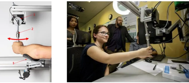
[image:5.612.117.481.437.598.2]In the last version (RobinHand L), the griping part which the operator holds in the hand during the manipulation of the motion controller has been improved. Now it is possible to perform the 7 degrees of freedom (7DOF). The degrees of freedom (ABC) that are used to control the tool/robot with additional articulated parts and the degree of freedom D that performs the opening and closing of the jaws of the instrument are carried out by the gripping part of the motion controller. The ergonomics of the gripping part have also been improved. Currently, it is adjusted to the operator's hands. The lines passing through the centres of the articulation elements intersect at exactly one point, between the operator's fingers. The force feedback is performed in the directions X, Y, and Z and in the jaw clamp D. Thanks to this solution, the manipulation of the motion controller became more intuitive. The construction of such complex shapes required the use of the latest technologies, manufacturing - 3D printing, as well as the connection of individual components (metal-plastic, metal-composite). Thanks to the use of rapid prototyping technology (3D printing with FDM method, used material: PCABS), it was possible to minimize the mass of the subassembly that was manipulated by the operator. This solution also allowed a shorter time for implementation of subsequent prototype versions. The minimum value of the force exerted on the user/surgeon was determined by using a test stand with one degree of freedom (Fig. 4).
Figure 4. Measuring stand for verification of force impacts on the operator.
was placed at the operator’s hand. This sensor recorded the current force exerted by the drive on the user. The position and the current in the motor were also recorded during the experiment. The operator notices the resistance of the arm movement, which he manipulated then he pressed the button under his foot. Tests were carried out on a group of 10 people during the Surgical Workshops organized by FRK. The exemplary results obtained from measurements for left and right movement and two braking strategies are shown in Figure 5. During the left-hand movement, the braking current grew dynamically as a function of the square difference between the actual and the set position. During the right-hand movement, the braking current increased linearly in the displacement function. The braking current was 500, 800, and 1500 mA, respectively. Figure 5 shows the results from a single measurement. The indication for reaching the breaking point is marked with red circles.
Figure 5. Exemplary results from an experiment of subjective sensation of braking.
Thanks to the use of rapid prototyping methods, the several conceptual models for mechanisms that implement the force feedback for displacements in X, Y, and Z axes were made. The laboratory stand to research different types of motors for haptic purposes was also developed. The tests with direct mechanism (the arm of the motion controller mounted on the motor shaft) and indirect mechanism (with using the transmission) were conducted. The tests were carried out including different types of drive systems, i.e. belts, and toothed and friction gears.
Various types of belts were used for the tests, i.e. metallic, plastic, and a combination of metallic and plastic materials.
controller. Reproducibility tests of performed movements (the impact of the material and braid of the cable to the slip) were carried out at the stand with indirect mechanisms. Values derived from encoders located on the active and passive shaft of the drive mechanism were used. The motor DC Maxon 32691 and MOK40-5000-1224-BZ-K from Wobit were used to drive the active shaft. For the purpose of determining the possible slip of the cable on the active pulley, a 24-hour tests research under the loading of 0.5N, 1N, and 3 N were conducted.
[image:7.612.103.488.277.480.2]Based on the conducted analyses, it is possible to conclude that the highest repeatability of the performed movements and minimal wear of the cable was observed for the mechanism with a cable made of plastic that is placed in guide grooves located on the drive wheel. The number of cable braids for the drive wheel was in range from 2 to 8.
Figure 6. Prototypes for variants of transmission: a) with direct drive mechanism, b) with using indirect mechanisms, c) mechanism with toothed belts, d), e) with using a belt drive
that are braided on the drive drum.
For the purpose of implementations of the force feedback in the end part of the motion controller, the various test variants of the part that is held by the operator were made using various mechanisms were made, e.g., belt drives or gear drives (Fig. 7). The tests were for two concepts: with one movable finger (index finger, Fig. 7a), and two fingers (index finger and thumb) working in parallel (Figs. 7b and c) are performed.
Figure 7. Concepts of the gripping part: a) one-sided mechanism, b) parallel jaws system with a belt drive, c) with a gear train.
Figure 8. Robin Heart Tele robot with a control console equipped with motion controller with force feedback.
CONCLUSIONS
[image:8.612.100.496.242.433.2]were obtained for gears with a cable made from plastic that is braided five times on the driving drum. On the driven wheel, the cable from one side is fixed and on the other hand it is tensioned with a spring. To perform the opening-closing action of the jaws of the instrument, the two-finger mechanism that works in parallel during the gripping is the most convenient solution for the operator. A belt drive was also used for this solution. As a part of further work, it is planned to use a belt drive instead the direct mechanisms.
ACKNOWLEDGMENT
This work was done in the frame of the project LIDER/32/0175/L-8/16/NCBR/2017.
REFERENCES
1. Nawrat, Z. 2011. “Robot chirurgiczny Robin Heart: Projekty, prototypy, badania, perspektywy”.
Postdoctoral thesis, Medical University of Silesia in Katowice.
2. Xin, H., J.S. Zelek, and H. Carnahan. 2006. “Laparoscopic surgery, perceptual limitations and
force: A review”, First Canadian Student Conference on Biomedical Computing, Kingston, Ontario, Canada, March 2006.
3. Nawrat, Z., P. Kostka, K. Lis, K. Rohr, Ł. Mucha, K. Lehrich, W. Sadowski, Z. Małota. 2013.
“Interfejs operatora robota chirurgicznego—oryginalne rozwiązania sprzężenia informacyjnego
i decyzyjnego”, Medical Robotics Reports, 2:12-21.
4. Podsękowski, L. 2010. Roboty medyczne—budowa i zastosowanie. Warszawa: WNT.
5. Lis, K., K. Lehrich, Ł. Mucha. 2015. “Robin Heart PortVisionAble - idea, design and preliminary
testing results”. Proceedings of the 10th International Workshop on Robot Motion and Control,
Poznan University of Technology, Poznan, Poland, July 6-8, 2015, pp. 176-181.
6. Mucha, Ł., Z. Nawrat, K. Lis, K. Lehrich, P. Kostka, W. Sadowski, D. Krawczyk, P. Kroczek, Z.
Małota, and Z. Nawrat. 2015. “Postępy budowy specjalnych interfejsów operatora robota
chirurgicznego Robin Heart”, Medical Robotics Reports, 4:49-55.
7. Lis, K., Ł. Mucha, K. Lehrich, Z. Nawrat. 2018. “RobinHand Haptic Device”, in Soft and
Stiffness-controllable Robotics Solutions for Minimally Invasive Surgery: The STIFF-FLOP Approach, J. Konstantinova, H. Wurdemann, A. Shafti, A. Shiva, K. Althoefer, eds. River Publishers, pp. 289-305.
8. Mucha, Ł. 2015. “Interfejs użytkownika robota—przegląd urządzeń zadawania ruchu systemów
sterowania telemanipulatorów”, Medical Robotics Reports, 4:39-48.
9. Mucha, Ł., K. Lis, K. Rohr, Z. Nawrat. 2016. Patent USA: 9393688, “Manipulator of a medical
device with auxiliary motor and encoder”, Current Assignee: Professor Zbigniew Religa Foundation of Cardiac Surgery Development.
10. Mucha, Ł., Z. Nawrat, K. Lis, K. Lehrich, K. Rohr, P. Fürjesb, C. Dücső. 2016. “Force feedback
control system dedicated for Robin Heart Pelikan”, Acta Bio-Optica et Informatica. Inżynieria
Biomedyczna, 22(3):146-153.
11. Nawrat, Z., K. Rohr, P. Fürjes, Ł. Mucha, K. Lis, J. Radó, C. Dücső, P. Földesy, W. Sadowski,
D. Krawczyk, P. Kroczek, G. Szebényi, P. Soós, Z. Małota. 2016. “Force Feedback Control
System Dedicated for Robin Heart Surgical Robot”, Procedia Engineering, 168:185-188.
12. Lee, D.H., U. Kim, T. Gulrez, W.J. Yoon, B. Hannaford, and H.R. Choi. 2016. “A Laparoscopic
Grasping Tool with Force Sensing Capability”, IEEE/ASME Transactions on Mechatronics,
13. Kim, U., D. Lee, W.J. Yoon, B. Hannaford and H.R. Choi. 2016. “Force Sensor Integrated
Surgical Forceps for Minimally Invasive Robotic Surgery”, IEEE Transactions on Robotics,
31(5):1214-1224.
14. Seibold, U., B. Kuebler, and G. Hirzinger. 2008. “Prototypic Force Feedback Instrument for
Minimally Invasive Robotic Surgery”, in Medical Robotics, V. Bozovic, ed. InTech Publishers,

![Figure 3. INCITE tool equipped with force sensors [11].](https://thumb-us.123doks.com/thumbv2/123dok_us/245527.1024412/4.612.103.495.585.666/figure-incite-tool-equipped-force-sensors.webp)