An IPM-CFAPSO based Hybrid Method for Multiple
Objective Minimizations using TCPS
M. Balasubba Reddy
Prakasam Engineering College Kandukur
India
Y.P. Obulesh
Phd, L.B.R. College of Engineering
Mylavaram India
S. Sivanaga Raju
Phd, J.N.T.U.College of Engineering
Kakinada India
ABSTRACT
This paper presents an Interior Pont Method (IPM) and vari-ant of Particle Swarm Optimization (CFAPSO) based hybrid method to solve optimal power flow in power system incorpo-rating Flexible AC Transmission Systems (FACTS) such as Thyristor Controlled Phase Shifter (TCPS) for minimization of multiple objectives. The proposed IPM-CFAPSO algorithm identifies the optimal values of generator active-power output and the adjustment of reactive power control devices. The proposed optimization process with IPM-CFAPSO is present-ed with case study example using IEEE 30-bus test system to demonstrate its applicability. The results are presented to show the feasibility and potential of this new approach.
Keywords
Optimal power flow, Constriction Factor Approach Particle Swarm Optimization, Flexible AC Transmission, and TCPS
1.
INTRODUCTION
The future growth of power system will rely more on increas-ing capability of already existincreas-ing transmission systems, rather than on building new transmission lines and power stations, for economic and environmental reasons. Due to deregulation of electricity markets, the need for new power flow controllers capable of increasing transmission capability and controlling power flows through predefined corridors will certainly in-crease. Ideally, these new controllers should be able to control voltage levels and flow of active and reactive power on transmission lines to allow for their secure loading, to full thermal capability in some cases, with no reduction of system stability security margins [1].
To meet the load demand in a power system and satisfy the stability and reliability criteria, the existing transmission lines must be utilized more efficiently. It provides an economically and technically attractive solution to power system security problem by use of some efficient controls, such as controlla-ble series capacitors, phase shifters, and load shedding, etc., [2]– [6]. Several techniques have been proposed in the past for the adjustment of phase shifter or the adjustment of con-trollable series capacitor to alleviate line overloads [5], [6].
The main method uses the model of series capacitor or phase shifter in power flow program without generation reschedul-ing. It is possible to alleviate power flow violation and en-hance power system security in an electrical power system by use of phase shifter without optimal generation rescheduling. However, it is well known that the phase shifter adjustment under given contingencies may fail to yield convergence. Thus, optimal power flow (OPF) with phase shifter is a good choice.
The goal of optimal power flow is to determine optimal con-trol variables and quantities for efficient power system plan-ning and operation. Several optimization techniques have been proposed to handle the OPF problem [7]–[9]. Recently, the research in OPF such as interior point (IP) using new op-timization techniques, has been gaining wider attention in power system operation [10], [11]. The interior point method is faster and more reliable for achieving feasibility and con-vergence. Due to the limitation of IP, the model of discrete variable such as phase shifter has not been investigated in the common OPF.
Heuristic algorithms, such as genetic algorithms (GA) [12] and evolutionary programming [13], have been recently pro-posed for solving the OPF problem. The results reported were promising and encouraging for further research in this direc-tion. Unfortunately, recent research has identified some defi-ciencies in GA performance [14]. This degradation in effi-ciency is apparent in applications with highly epistatic objec-tive functions, i.e. where the parameters being optimized are highly correlated. In addition, the premature convergence of GA degrades its performance and reduces its search capabil-ity.
Recently, a new evolutionary computation technique, called particle swarm optimization (PSO), has been proposed and introduced [15-18]. This technique combines social psycholo-gy principles in socio-cognition human agents and evolution-ary computations. PSO has been motivated by the behavior of organisms such as fish schooling and bird flocking. Generally, PSO is characterized as simple in concept, easy to implement, and computationally efficient. Unlike the other heuristic tech-niques, PSO has a flexible and well-balanced mechanism to enhance and adapt to the global and local exploration abilities.
This paper presents an IPM-CFAPSO (Interior Point – Con-striction Factor Approach Particle Swarm Optimization) inte-grated hybrid approach to study the OPF with TCPS for mul-tiple objective minimizations. The objective functions of OPF include minimization of real power generation cost, voltage deviation, voltage stability index and real power loss. The proposed approach is examined with the IEEE 30-bus test system with one TCPS at a time.
2.
FACTS DEVICES
Several techniques have been proposed in the past for the adjustment of phase angles of phase shifter to alleviate line overloads [20-22].The optimal power flow (OPF) with phase shifter is a good choice. In order to retain the symmetry of Y bus, the injection model of phase shifter used in [23-24] is adopted in this paper. The proposed approach is tested on an IEEE 30-bus test system with a phase shifters located in a transmission line.
i) Phase Shifter Modelling
[image:2.595.64.283.289.375.2]A flexible power flow model for the phase-shifting transform-er is described in this section. It is dtransform-erived from the two wind-ing, single-phase transformer model, which contains complex taps on both the primary and secondary windings. The Thyris-tor Controlled Phase shifter circuit diagram can be represented by Figure 1. Due to the installation of phase shifter, the sys-tem will have lots of benefits such as overload release, syssys-tem loss reduction and generation adjustment reduction.
Figure 1 Circuit diagram of phase shifter
It is reasonable to assume that the phase-changing facility is
only on the primary side, (i.e.
=0); the primary and sec-ondary windings admittances may be combined together [)]
/(
scp scs scsscp
Y
Y
Y
Y
Y
; and the impact ofmagnetiz-ing branch is negligibly small in the power flow solution.
)
0
(
Y
0
:
m k mm mk km kk m k m kV
V
Y
Y
Y
Y
V
V
Y
j
Y
j
Y
Y
I
I
)
sin
(cos
)
sin
(cos
(1 )Similar to the power flow LTC model, it is assumed in this expression that the primary and secondary sides of the trans-former are connected to bus k and bus m, respectively. Also, the subscripts k and m are dropped in the admittance term and in the phase angle
, respectively. Based on equation (1), equations for the nodal power injections of the phase-shifting transformer, where
is allowed to vary within designrating values (
min
max), are as follows:
cos(
)
sin(
)
2 m k km m k km m k kk k
k
V
G
V
V
G
B
P
(2)
sin(
)
cos(
)
2 m k km m k km m k kk k
k
V
B
V
V
G
B
Q
(3)
cos(
)
sin(
)
2 k m mk k m mk k m mm m
m
V
G
V
V
G
B
P
(4)
sin(
)
cos(
)
2 k m mk k m mk k m mm m
m
V
B
V
V
G
B
Q
(5)Where
).
sin
(cos
),
sin
(cos
,
,
j
Y
jB
G
Y
j
Y
jB
G
Y
Y
jB
G
Y
Y
jB
G
Y
mk mk mk km km km km mm mm kk kk kk (6)Alternatively, substituting equations (6) into equations (2)-(5) leads to the following more explicit expressions:
cos(
)
sin(
)
2
k k m k m k mk
V
G
V
V
G
B
P
, (7)
sin(
)
cos(
)
2
k k m k m k mk
V
B
V
V
G
B
Q
, (8)
cos(
)
sin(
)
2
m m k m k m km
V
G
V
V
G
B
P
, (9)
sin(
)
cos(
)
2
m m k m k m km
V
B
V
V
G
B
Q
, (10)If the phase-shifting transformer is used to control the active power flowing through it at a specified value then the Jacobi-an is enlarged to accommodate one additional equation. In this situation
enters as an extra state variable in the Jacobian equation. If the control is extended at the sending end (bus k)of the phase shifter then
P
kmpsis the target power to be regu-lated.The set of linearized power flow equations for the phase– shifting transformer is,
) ( ) ( ) ( i ps m m k k m k i km m m km k k km m km k km m m m m k k m m m k m k m m k k k k m k k k m m m m k k m m m k m k m m k k k k m k k k i ps km m k m k
V
V
V
V
P
V
V
P
V
V
P
P
P
Q
V
V
Q
V
V
Q
Q
Q
Q
V
V
Q
V
V
Q
Q
Q
P
V
V
P
V
V
P
P
P
P
V
V
P
V
V
P
P
P
P
Q
Q
P
P
(11)where
P
kmps, given by
P
kmps
P
km,reg
P
kmps, is the active power flow mismatch for the phase shifter;P
kmps is the calculated power as given by equation (7);
PS, given by
PS
(i)
(i1), is the incremental change in the phase shifter angle at the ith iteration.3.
MATHEMATICAL MODEL OF OPF
PROBLEM
satisfying several equality and inequality constraints. Mathe-matically, the OPF problem can be formulated as given
Min
J
(
x
,
u
)
(12)Subject to
g
(
x
,
u
)
0
(13)0
)
,
(
x
u
h
(14)where x is a vector of dependent variables consisting of slack
bus power
1
G
P
, load bus voltagesV
L, generator reactive power outputsQ
G, and the transmission line loadingsS
l, Hence, x can be expressed as given]
...
,
...
,
...
,
[
1 1
1 L LNL G GNG l lnl
G T
S
S
Q
Q
V
V
P
x
(15)where NL,NG and nl are number of load buses, number of generators and number of transmission line respectively.
u is the vector of independent variables consisting of generator voltages VG, generator real power outputs
P
Gexcept at the slack bus
1
G
P
, transformer tap settings T, and shunt VAR compensationsQ
C. Hence u can be expressed as given]
...
,
...
,
...
,
...
[
1 2
1 GNG G GNG 1 NT C CNC
G T
Q
Q
T
T
P
P
V
V
u
(16)Where NT and NC are the number of the regulating trans-formers and shunt compensators, respectively. F is the objec-tive function to be minimized. g is the equality constraints that represents typical load flow equations and h is the system operating constraints
4.
OBJECTIVE FUNCTIONS
In this paper, the objective(s)(J)is the objective function to be minimized, which is one of the following:
(i)Objective function-1 ( Fuel cost minimization)
It seeks to find the optimal active power outputs of the gen-eration plants so as to minimize the total fuel cost. This can be expressed as
)
/
($
h
f
J
NG
i i
(17)where
f
i is the fuel cost curve of the ith generator and it is assumed here to be represented by the following quadratic function:)
/
($
2
h
c
P
b
P
a
f
i i G i G ii i
(18)where
a
i,b
i, andc
i are the cost coefficients of thei
th generator.(ii) Objective function-2 ( Voltage profile improvement)
Voltage profile is one of the quality measures for power sys-tem. It can be improved by minimizing the load bus voltage deviations from 1.0 per unit. The objective function can be expressed as
NL i
i
V
J
1
(19)(iii) Objective function-3 (Voltage stability enhancement)
Voltage profile improvement does not necessary implies a voltage secure system. Voltage instability problems have been experienced in systems where voltage profile was acceptable [25]. Voltage secure system can be assured by enhancing the voltage stability profile throughout the whole power system.
An indicator L-index is used in this study to evaluate the volt-age stability at each bus of the system. The indicator value varies between 0 (no load case) and 1 (voltage collapse) [26-28].One of the best features of the L-index is that the compu-tation speed is very fast and so can be used for on-line moni-toring of power system. Enhancing the voltage stability and moving the system far from voltage collapse point can be achieved by minimizing the following objective function
max
L
J
(20)where
L
max is the maximum value of L-index as
L
K
NL
L
max
max
K,
1
,...,
(21)(iv) Objective function-4 (Real power loss minimization)
The optimal reactive power flow problem to minimize active losses can be formulated as
max min
0
)
(
.
)
(
min
g
t
s
f
J
(22)
Where
f
(
)
Objective function for active losses)
(
g
Nonlinear vectors function rep-resenting power flow equations
Tu
x
Vector of decision variables whose components are the vector of state varia-blesx
(voltage phase angles and magnitudes, etc.) and the vector of discrete control variables u (gener-ator terminal voltages, tap position of OLTC trans-formers, number of connected shunt compensation devices etc.).min
and
max vectors modeling operational limits on state and control variables(v) Constraints
Equality Constraints: These are the sets of nonlinear power flow equations that govern the power system, i.e,
0
)
cos(
1
j ij ij i j
n
j i Di
Gi
P
V
V
Y
P
(23)0
)
sin(
1
j ij ij i j
n
j i Di
Gi
Q
V
V
Y
Q
(24)where
P
Gi andQ
Giare the real and reactive power outputs injected at busi
respectively, the load demand at the samebus is represented by
P
DiandQ
Di, and elements of the bus admittance matrix are represented byY
ij and
ij.Inequality Constraints: These are the set of constraints that represent the system operational and security limits like the bounds on the following:
1) generators real and reactive power outputs
P
GiP
GiP
Gi,
i
1
,
,
N
max
min
(25)
Q
Gimin
Q
Gi
Q
Gimax,
i
1
,
,
N
(26) (26)2) voltage magnitudes at each bus in the network
V
iV
iV
i,
i
1
,
,
NL
max
min
(27)
3) transformer tap settings
T
imin
T
i
T
imax,
i
1
,
,
NT
(28)4) reactive power injections due to capacitor banks
Q
Cimin
Q
Ci
Q
Cimax,
i
1
,
,
CS
(29)5) transmission lines loading
S
i
S
imax,
i
1
,
,
nl
(30)(30)
6) voltage stability index
Lj
i
Lj
imax,
i
1
,
,
NL
(31)The equality constraints are satisfied by running the power
flow program. The generator bus terminal voltages (
V
gi), transformer tap settings (t
k) and the reactive power genera-tion of capacitor bank (Q
Ci) are the control variables and they are self-restricted by the representation itself. The activepower generation at the slack bus (
P
gs), load bus voltages (Li
V
) and reactive power generation (Q
gi), voltage stability (j
L
-index) are state variables which are restricted through penalty function approach.(vi) FACTS devices constraints:
i) TCPS constraints
max min
Pi Pi Pi
Phase angle constraint of TCPS (32)where
Pi= Phase shift angle of TCPS at line imax min
,
Pi Pi
= Lower and upper phase shift angle limits of TCPS at line i5.
OVERVIEW OF PSO
The PSO technique is an evolutionary computation technique, but it differs from other well-known evolutionary computation algorithms such as the genetic algorithms. Alt-hough a population is used for searching the space, there are no operators inspired by the human DNA procedures applied on population. Instead, in PSO, the population dynamics sim-ulates a ‘bird flock’s’ behavior, where social sharing of in-formation takes place and individuals can profit form the dis-coveries and previous experience of all the other companions during the search for food.
Thus, each companion, called particle, in the popu-lation, which is called swarm, is assumed to ‘fly’ over the search space in order to find promising regions of the land-scapes. For example, in the minimization case, such regions possess lower function values than other, visited previously. In this context, each particle is treated as a point in a D-dimensional space, which its own ‘flying’ according to its flying experience as well as the flying experience of other particles (companions). In PSO, a particle is defined as mov-ing point in hyperspace. For each particle, at the current time step, a record is kept of the position, velocity, and the best position found in search space so far.
6.
Constriction Factor Approach PSO
(CFAPSO)
The basic system equation of PSO (33, 34 and 35) can be considered as a kind of difference equation.
)
(
*
)
(
*
2 21 1
1 k
i k
i i k
i k
i
wv
c
rand
pbest
s
c
rand
gbest
s
v
(33)iter
iter
w
w
w
w
max
((
max
min)
/(
max))
*
(34)
s
ik1
s
ik
v
ik1 (35)
)]
(
*
)
(
*
*
[
1 1 2 21 k
i k
i i k
i k
i
K
v
c
rand
pbest
s
c
rand
gbest
s
v
(36)
,
4
2
2
2
K
(37)where
c
1
c
2,
4
where
and K are coeffi-cients.7.
OVERALL COMPUTATIONAL
PRO-CEDURE FOR SOLVING THE
PROB-LEM
The implementation steps of the proposed IPM-CFAPSO based algorithm can be written as follows;
Step 1: Input the system data for load flow analysis
Step 2: Run the power flow
Step 3a: Select a FACTS device and its location in the system
Step 3b: At the generation Gen =0; set the simulation parame-ters of IPM-CFAPSO parameparame-ters and randomly initialize k individuals within respective limits and save them in the archive.
Step 4: For each individual in the archive, run power flow to determine load bus voltages, angles, load bus voltage stability indices, generator reactive power outputs and calculate line power flows.
Step 5: Evaluate the penalty functions
Step 6: Evaluate the objective function values and the corre-sponding fitness values for each individual.
Step 7: Find the generation local best xlocal and global best
xglobal and store them.
Step 8: Increase the generation counter Gen = Gen+1.
Step 9: Apply the IPM-CFAPSO operators to generate new k individuals
Step 10: For each new individual in the archive, run power flow to determine load bus voltages, angles, load bus voltage stability indices, generator re-active power outputs and calculate line power flows.
Step 11: Evaluate the penalty functions
Step 12: Evaluate the objective function values and the corre-sponding fitness values for each new individu-al.
Step 13: Apply the selection operator of IPM-CFAPSO and update the individuals.
Step 14: Update the generation local best xlocal and global best xglobal and store them.
Step 15: If one of stopping criterion have not been met, repeat steps 4-14. Else go to stop 16
Step 16: Print the results
8.
SIMULATION RESULTS
The simulation results of the proposed hybrid OPF method with TCPS for different objective functions (i.e. fuel cost minimization, voltage profile improvement, voltage stability enhancement, and real power loss minimization) have been applied to IEEE-30 bus system with NR-load flow, Newton-OPF Interior Point-Newton-OPF and IPM-CFAPSO with TCPS meth-ods. The approach can be generalized and easily extended to large-scale systems.
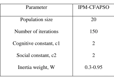
[image:5.595.331.525.367.500.2]The IEEE-30 bus system consists of six generators, four trans-formers, 41 lines, and nine shunt capacitors. In this PSO vari-ant method, the total control variables are 25: six unit active power outputs, six generator bus voltage magnitudes, four transformer tap settings, and nine bus shunt admittances. The proposed algorithms are implemented using MATLAB 7.1 running on Pentium IV, 2.66GHz, and 512MB RAM personal computer. The IPM-CFAPSO parameters used for the simula-tion are summarized in Table 1
Table 1
Optimal parameter settings for IPM-CFAPSO
Parameter IPM-CFAPSO
Population size
Number of iterations
Cognitive constant, c1
Social constant, c2
Inertia weight, W
20
150
2
2
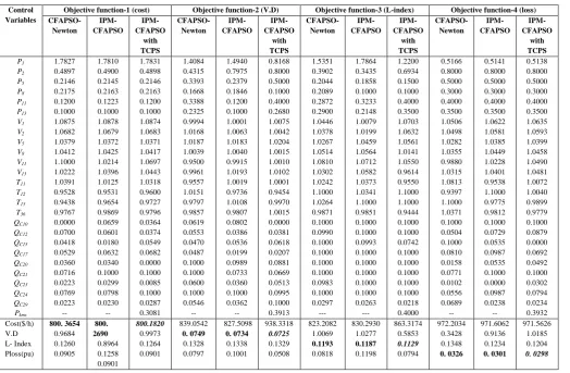
Table 2 Optimal settings of control variables of IEEE 30-bus system in CFAPSO based OPF method
Control Variables
To test the ability of the proposed hybrid algorithms along with TCPS for solving optimal power flow problem to reduce specified objective function, it was applied on selected bus system. One TCPS is installed. TCPS is installed at line con-nected between buses 15 and 18 with line real and reactive power settings of TCPS, Pmk = 0.10, Qmk = 0.01 and –п/4 ≤
pi≤ п/4. Four objective functions are considered for the
min-imization using the proposed hybrid algorithm namely cost of generation, voltage profile improvement, voltage stability enhancement and real power loss minimization.
The best results for CFAPSO method combined with NR-load flow, Newton-OPF, and Interior Point method are compared and results are tabulated in Table 2. In this table, the optimal settings of the control variables and various performance pa-rameters with four objective functions are presented. From Table 2, it was found that all the state variables satisfy lower and upper limits. From the results it is evident that proposed IPM-CFAPSO hybrid method along with TCPS outperforms in achieving minimum of the specified objective when com-pared with other optimization methods.
9.
CONCLUSION
In this paper, a new IPM-CFAPSO hybrid method has been presented to solve the optimal power flow problem with a FACTS device. The proposed method introduces the voltage source model of FACTS devices into a conventional AC op-timal power flow problem to exploit the new characteristic of FACTS devices. Case studies on IEEE-30 bus test system show the potential for application of IPM-CFAPSO to achieve different objectives with FACTS. It has been shown that the FACTS devices can effective in achieving the specified objec-tives.
10.
ACKNOWLEDGEMENT
There are several people we would like to thank. First, we would like to thank Dr. Kancharla Ramaiah, correspondent and secretary of Prakasam Engineering College,Kandukur, India for his encouragement and support and providing us with the facility for completing this paper.
11.
REFERENCES
[1] O. Alsac, and B. Sttot, ‘’Optimal power flow with steady-state security”, IEEE Trans. on Power Systems, Vol. 93, 1974, pp. 745-751.
[2] N. Srinivasan, K. S. Prakaesa, and S. S. Venkata, “On-line computation of phase shifter distribution factors and line load alleviation,” IEEE Trans. on Power Systems, vol. PAS-104, no. 7, pp. 1656–1662, 1985.
[3] B. Stott and E. Hobson, “Power system security control calculations using linear programming—Part I,” IEEE Trans. On Power Systems, vol. PAS-97, pp. 1713–1719, 1978.
[4] R. Baldick and E. Kahn, “Contract paths, phase shifters, and efficient electricity trade,” IEEE Trans. on Power Systems, vol. 12, no. 2, pp.749–755, 1997.
[5] M. R. Iravani and D. Maratukulam, “Review of semicon-ductorcontrolled (static) phase shifters for power system applications,” IEEE Trans. on Power Systems, vol. 9, no. 4, pp. 1833–1839, 1994.
[6] T. K. P. Medicherla, R. Billinton, and M. S. Sachdev, “Generation rescheduling and load shedding to alleviate
line overloads— Analysis,” IEEE Trans. on Power Sys-tems, vol. PAS-98, pp. 1876–1884, 1979.
[7] A. D. Papalexopoulos, C. F. Imparato, and F. F. Wu, “Large scale optimal power flow: Effects of initialization decoupling and discretization,” IEEE Trans. on Power Systems, vol. 4, pp. 748–759, 1989.
[8] O. Alsac and B. Sttot, “Optimal power flow with steady-state security,” IEEE Trans. on Power System, vol. 93, pp. 745–751, 1974.
[9] J. Z. Zhu and G. Y. Xu, “A new real power economic dis-patch method with security,” Electric Power Systems Re-search, vol. 25, no. 1, pp. 9–15, 1992.
[10] S. Granville, J. C. O. Mello, and A. C. G. Melo, “Appli-cation of interior point methods to power flow unsolva-bility,” IEEE Trans. on Power System, vol. 11, pp. 1096– 1103, 1996.
[11] J. A. Momoh, L. G. Dias, S. X. Guo, and R. A. Adapa, “Economic operation and planning of multi-area inter-connected power system,” IEEE Trans. on Power Sys-tem, vol. 10, pp. 1044–1051, 1995.
[12] Lai LL,Ma JT. Improved genetic algorithms for optimal power flow solutions under both normal and contingent operation states.Int J Elec Pwr Syst 1997;19(5):287-92.
[13] Yuryevich J,Wong KP.Evolutionary programming based optimal power flow algorithm. IEEE Trans Pwr Syst 1999;14(4):1245-50.
[14] Fogel DB.Evolutionary computation toward a new phi-losophy of machine intelligence.New York:IEEE Press, 1995.
[15] Kennedy J.The particle swarm: social adaptation of knowledge.Proc 1997 IEEE Int Conf Evol Comput ICEC,97,Indianapolis,IN,USA 1997:303-8.
[16] Angeline P.Evolutionary optimization versus particle swarm optimization:philosophy and performance differ-ences.Proc 7th Annu Conf Evol Prog 1998:601-10.
[17] Shi Y,Eberhart R.Parameter selection in particle swarm optimization.Proc 7th Annu Conf Evol Prog 1998:591-600.
[18] Ozean E,Mohan C.Analysis of a simple particle swarm optimization system.Intel Engng Syst Artif Neural Net-works 1998;8:253-8.
[19] N.Acharya, A.Sody-Yome, N.Mithulananthan, Facts about flexible ac Transmission systems(FACTS) control-lers: Practical installations and benefits, in: Australasian Universities Power Engineering Conference (AUPEC),Australia, September 25- 28,2005,pp.533-538
[22] M.R. Iravani, and D. Maratukulam, “Review of semicon-ductor-controlled (static) phase shifters for power system applications,” IEEE Trans. on Power Systems, Vo1.9, No.4, 1994, pp 1833-1839
[21] J.A. Momoh, J.Z. Zhu, and J.L. Dolce, “Optimal load shedding study of space station power system using gen-eralized Lagrangian multipliers,” Proceedings of 1998 Large Engineering Systems Conference on Power Engi-neering, LESCOPE’98, Canada, 7-10 June, 1998.
line overloads - analysis,” IEEE Trans. on Power Sys-tems, Vol.PAS-98, 1979, pp. 1876-1884.
[23] N. Srinivasan, K.S. Prakaesa, and S.S. Venkata, "On-line computation of phase shifter distribution factors and line load alleviation," IEEE Trans. on Power Systems, Vol.PAS-104, No.7, 1985, pp 1656-1662
[24] B. Stott, and Eric Hobson, "Power system security con-trol calculations using linear programming, Part I," IEEE Trans. on Power Systems, Vol. PAS-97, 1978, pp 1713-1719.
[25] Overbye T. and DeMarco C., “Voltage Security En-hancement Using Energy Based Sensitivities”, IEEE Trans. On Power Systems, Vol. 6, No. 3, August 1991, pp. 1196-1202.
[26] Kim S., Song T., et al, “Development of Voltage Stabil-ity Constrained Optimal Power Flow (VSCOPF)”, Power
Engineering Society Summer Meetings, 2001 IEEE, Vol. 3, 15-19 July 2001, pp. 1664-1669.
[27] Tuan T.Q., et. al., “Emergency Load Shedding to Avoid Risks of Voltage Instability Using Indicator”, IEEE Trans. On Power Systems, Vol.9, No. 1, February 1994, pp. 341-347.
[28] Kessel P. and Glavtisch H., “Estimating the Voltage Stability of a Power System”, IEEE Trans. on Power De-livery, Vol.1, No.3, 1986, pp. 346-354.
[29] Kennedy J, Eberhart R. Swarm intelligence. San Mateo, CA: Morgan Kaufmann; 2001.