Displacement on Non-Linear Analysis in Different
Construction Stages of Bakun CFRD
Mohd Hilton ~ h m a d ' and Jamaloddin ~oorzaie' ,Fayda A1 ~ b a d i ~
I
Structural and Material Engineering Dept, Faculty of Civil and Environmental Engineering, Universiti Teknologi Tun Hussein Onn Malaysia (UTHM),
86400 Parit Raja, Batu Pahat, Johor.
2
Civil Engineering Department, Faculty of Engineering, Universiti Putra Malaysia (UPM), 43400 UPM Serdang, Selangor.
Email: [email protected]
,
[email protected]Abstract - Bakun Concrete Faced Rockfill Dam (CFRD) become second highest CFRD in the world is analyzed for its structural response due to its self-weight by using Finite Element Method. Non-linear Duncan-Chang hyperbolic Model is used to study the structural response of the dam in respect to the deformation and stresses of Main dam of Bakun's CFRD project. The model was modeled as 2-D and analyzed as plain strain problem by using isoparametric elements, interface elements and infinite elements to represent the entire element been meshed. Dead-Birth-Ghost element technique was used to simulate sequences of construction of the dam. The comparison of rigid and flexible foundation on the behaviour of the dam was discussed. The maximum horizontal and vertical displacement of the cross section at different stages of construction was founded and the distribution of them were discussed in form of graphs and contours.
Key words : CFRD dams, non-linear analysis, Finite
element method, flexible foundation, construction stage
Dams form as a part of controlled irrigation system,. flood control, hydroelectric power generation and also as soil conservation. There are a few factors need to be taken care .of when designing a dam, i.e. safety, economy, efficiency and appearance. Safety and economy are factors that contradict to each other; however, we may design an economical dam without sacrificing the safety of the dam. In this paper, Bakun Dam which become the second highest Concrete Faced Concrete Dam (CFRD) in the world when expected to be completed in early 2010 is analyzed to its safety by using finite element method. Dam structure often store huge quantity of water at great potential energy and if in the case of failure does pose an imminent threat to population and property downstream. There are many cases reported due to dam failure and it cause very severe damages.
To date, a common assumption in modeling soil-structure interaction by earlier researchers and particularly [2-61, CFRD researchers is that they simulated their program with the foundation as rigid foundation (boundary fixation at the base of the dam), which leads to ignoring differential ground motions and its effects to the dam. This reduces the complexity of the problem (i.e. the number of additional degrees of freedom for accounting for the interaction), and make it possible to present general results.
However, this does not present the actual situation, where a dam must rest on the foundations. Therefore, this study will include the effect of foundation (flexible foundation) with infinite elements.
The study of structural response of the dam is based on horizontal and vertical displacement which is the principal safety evaluation of Bakun Dam structure. By using provided 2-D program, the study of structural response of Bakun CFRD is being done. The written program has simulation of Birth, Dead and Ghost element techniques, input parameters for the material linear analysis, contact between any different material represent interface behavior, and simulation of loading during dam construction and reservoir filling. This paper will discuss the result obtained from the analysis at few specified stages of construction which compares the analysis of Bakun Dam in two cases i.e. Main Dam with rigid foundation as well as with flexible foundation.
The finite element method (FEM) is a powerful tool for numerical procedures for analyzing structures and continua. Problems involving long bodies, whose geometry and loading do not significantly in the longitudinal direction, are refereed to as the cases of plane strain. Finite element analysis has been used to study the behaviour of rockfill and to predict strains in various portions of the rockfill. The results so far obtained are promising and the method would be used more widely in future.
The isoparametric formulation makes it possible to generate elements that are non-rectangular and have curved sides. In formulating isoparametric elements, natural coordinate systems must be used f (i; rl) Whereby, displacements are expressed in terms of natural coordinates, but must be differential with respect to global coordinates x, y and z.
respect to and q may be expressed in matrix form as
The rockfill embankment in CFRD represents by eight- noded isoparametric elements or in CFRD analysis known as parabolic elements. This element gives a quadratic variation of strain. The trapezoidal element containing eight nodes can give solutions for eight unknowns. This element gives a quadratic variation of strain. The stiffness matrix is the summation of the quantities at nine integration points (Gaussian Points). Here, the stiffness matrix in the local coordinates is written as
In general, CFRD dam built on the soil. Modulus of elasticity of soil (ESoi3 and concrete (Cco,J is totally different. Thus need a surface between these two elements which is known as "INTERFACE". Two parameters been introduced in interface element which is Kss, denotes the shear stiffeness and K,,, is the normal differential displacements. The stiffness matrix of the interface element can be written as:
Development of infinite elements has helped in proper physical modeling of the far field behaviour and also reduction in number of elements and also the computational cost. There are two types of infinite elements, namely, mapped type and decay type. However mapped typ:d always been used. Improved infinite element based on mapping for modeling of unbounded domain problem. By mapping of -1 5 g 2 +I , the following expression will be obtained;
MODELLING OF BAKUN CFRD
A. Bakun CFRD Features
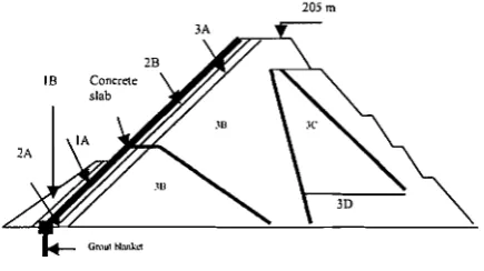
The Bakun Hydroelectric Power Dam, which is located on the Balui River in Belaga District in Sarawak Malaysia, which costs RM5.8 billion. The Bakun dam will be 205 metres high with an approximate crest length of 748.85 metres and fill volume of approximately 17,000,000m3. The face of this Concrete Face Rockfill Dam is essentially a slab of concrete placed against rockfill on the upstream slope that extends from the dam crest to the plinth. Excavation of earth and soil is camed out before the plinth is constructed from concrete. A 7.5m high "L" type
concrete parapet wall at the upstream of the crest to serve as access road with a dam slope of 1V:1.4H at the upstream and lV1.3H at the downstream. Based on Sarawak Hidro Sdn. Bhd. 2003 [I], the dam consists of different zones as shown in Fig. 1.
IB Concrete
Fig. 1 : Different zones in Bakun Dam
B. Pre-processing stage
This dam is modeled as two-dimensional structure and then divided into few layers and each layer discrete into few elements comprising of nodes depending on types of element. The geometry of the dam and the material properties in each section of the dam is designed based on actual data. Each element is discretized accordingly to respective layer and fit the type of material comprising in respective section of the dam model. For soil-structure interaction problems, in our case layer between main dam and concrete face were based that there is no slip between the structures and the soil or that there is no possibility for shear stresses to develop (interface is perfectly smooth). There are two cases of dam been considered; namely rigid foundation and flexible foundation as shown in Fig. 2.
Both cases are modeled as follows:-
(a) Dam without Foundation (Rigid Foundation)
In this case, the dam is designed on a fixed base or rigid foundation. The dam is divided into eight layers, divided into 28 layers, and then each layer discrete into 936 elements gave a total of 2870 nodes. There are 3 types of isopaametric elements used in this case; namely 8 noded isoparametric element, 6 noded isoparametric element, and interface isoparametric element. In this case, the boundary condition is fixed at the base of the dam.
(b) Dam with Foundation (Flexible Foundation)
For the case of dam with foundation, the model of main dam is same as prior case and adding the foundation at the bottom of the main dam. The foundation is divided into four layers, and each layer has infinite elements on both sides. Addition to the 4 layers of foundation gave increment of 170 elements and 508 nodes gave sum of 1103 elements and 3378 nodes. The dam which divides into 32 layers is assumed to be fixed at 40m below the foundation level. Addition of infinite element gave total of 4 types of elements in this case.
[image:2.595.316.534.119.241.2]geotechnical problems like high B a h n dam, the non- linearity arises from the stress dependence of the stress- strain material parameters. The isotropic hyperbolic model which is implemented in this study can directly capture the non-linear behaviour and pressure-dependency effects and generate the E, at each level of loading, which includes constitutive parameters according to E-B parameters such as K, n, Rj p, Ap, Kb, K
,,,,
m are listed in Table 1 (Sarawak [image:3.594.304.537.49.174.2]Hidro Sdn. Bhd.).
Table 1 : Parameters for Duncan's E-B Model
The Birth, Dead and Ghost element techniques which used by Norzaie has been used in Finite element program to simulate the sequence of construction of the dam and each layer is loaded with stage of construction. At reservoir filling stage analysis, At the end of B a h n dam construction, it is planned to impound water after the completion of dam body, and in the analysis the reservoir was considered to be filled in a single stage. Water loading applied normal to the upstream face.
ANALYSIS AND RESULTS
A. Analysis of Non-Linear During Sequence of
construction
In static analysis, the response of structure or material is directly proportional to the load applied, where Hooke's Law applied, or in simple relationsh~p (F = K x 6) and
deflection is easily obtained by dividing force (F) by
stiffness (K). However, many real physical situation
exhibit a behaviour where is Hooke's Law is no more applicable (F f K x 6) and these are described as 'non-
linear problems'. For the analysis purposes, for case without foundation, the specified stages are stage lS', 41h, 61h, gth, 131h, 16Ih, 21St, 241h and 281h. On the other hand, for with foundation, stages have been specified as lS', 4Ih, 8Ih,
loth, 131h, 17Ih, 2oth, 2sth, 28Ih, and 32nd stage.
The stages for both cases are parallel on each other. From all the graphs displayed, we can notice a down-curved hyperbolic (resemljle to a deflection shape) which signifies the maximum displacement occurred almost at the middle point along the x-axis in all signified elevation level as shown in Fig. 2. This shape also same to the linear analysis (only different is the intensity of deformation). By comparison between cases of analysis, flexible foundation gave bigger value compared to rigid foundation. This may because of the properties of soil that can heave from sides.
I Vertical Displacement olBakun Dam alone the diitame fmmx-axis at
Foundation Level (Om). With Foundation I
'
0 0'
E1
z 4 5 ; -101 a
1 g-15 $ - 2 0 p - 2 5
+
4 0 s3 5
-- -
+% 32 Slg 28 - s t g 2 5
t Sfg 20
-
Slg 17 Is g to
- - -
1 - - -
- S f g B - - s 1 g 4
- - - - - -- - - - -- -1 -- - -
Fig. 2: Vertical Displacement at foundation level at different stages of construction for with and without (rigid)
foundation.
The plot of Y/H (height specified over the total height)
versus vertical displacement are shown in Fig. 3. It shows the plots of vertical displacement along the centerline of the dam (x = 284.6m). For the case of flexible and rigid
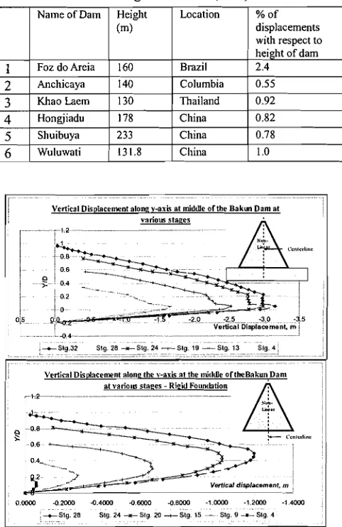
foundation, the maximum value of vertical displacement at the midheight is given as 3.2m and 1.25m respectively and placed almost close to the foundation level and mid-height of the dam respectively. The percentage of displacements respect to the height of B a h n dam is given as 1.7 1 % and 0.61% respectively. This is considers good result comparing with observed and computed values of the existing dams in the world shown in Table 2. The ratio of
Y/H where these maximum displacements occurs is 0.15
[image:3.594.309.550.411.782.2]and 0.5 respectively.
Table 2: Ratio's of Maximum Vertical Displacements (in terms of height of the dam, Y/H)
-
Vertical Displacement alanz v-axis at middle ofUle Bakun Dam at
variola staqes
I
t S l g 32 Stg 28 t S l g 24 -Slg 19
-
Slg 13 Slg 4- - - I
- - - - - --
- - - -
- I
VellimlDisplacement alone the \,-axis at the mirldle oftheBakunDan1
at variola staces - Rieid Founclation
00000 4 2 W O 44000 O M 0 0 4 8 W O - 1 M m 42000 -14WO
Fin. 3: Vertical Displacement at the middle cross section in y-axis at different stages of construction for flexible
(top) and rigid foundation (bottom).
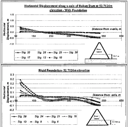
For horizontal displacement along y-axis at the centreline of the dam is shown in Fig. 5. Basically, horizontal
-
-
- displacement gave more stiff, thus gave smaller value of displacement compared to vertical displacement in static analysis. This o w k g to the movement bf dam downwards because of weight of the dam which filled by rockfill mass. This is called "overburden" phenomena. The maximum value of horizontal displacement is given by 0.2m for rigid foundation and 0.4m for flexible foundation. Both of the values given at 52.7 m elevation as given in Fig. 4. From Fig. 5, it the later stage of construction (stage 25 and above), the biggest displacements occur at the downstream face for elevation more than 1 10. lm. This is different from elevation less than 52.7m as shown in Fig. 4, the larger horizontal displacement occurs closer to the upstream side compared to the downstream side.-- - - - - -- -
TI
D b d r e n n t alonr x-ails o I B a k u n D m a1 12 7I2Imelevation
-
\Wth Fo~mclal~oni 1 5 ,
----
I-+-Slg 32 Slg 28 -Slg 25 -Slg 20j
1
---... ..
/ - Slg 17 SIg 13
.
Slg 70I . - .-
- -- --
[image:4.594.307.536.48.272.2]- - - -- -> 1
Fig. 4: Horizontal Displacement at 52.7126m elevation at different stages of construction for with (top) and without
foundation (bottom).
There is almost no displacement (very small value) at the middleline of the dam, increases as it goes towards the upstream and downstream faces as shown in Figure 5. However, the value of displacement does not symmetrical on both sides. At the downstream side, it shows more displacement value. This may due to the geometry of the dam itself. Maximum values are given at Y/H = 0.6 for
flexible foundation and Y/H = 0.62 for rigid foundation.
Maximum values of displacement are given as 0.125m and 0.06m respectively. At the stage of 24lh and 28lh, it gave for rigid foundation and flexible foundation respectively the biggest value of horizontal displacement. As we can see, the displacement at the upstream face is less than downstream face for both cases because of existence of concrete face at the upstream slope and shown its stiffness behaviour.
Honmnlal cbsplacrmcnt alonR ,-axis tn mlddlc oIBakun Dam nlth vanour
stnets- M t h Foundation
t S I g 32 Stg 28 +-St9 24
1 Stg 19 - Stg 13 Stg 3
,
- -- -.
- --- -- -
Horizontal D a d n c e m n t alone y-axis at the middle orthe damn>th
various slaeer - Rkid Foundation
-.( 2 .--. - -- -- I
i
I . .. -. -
Fig. 5: Horizontal Displacement at the middle cross section in y-axis at different stages of construction for with
(top) and without foundation (bottom).
Fig. 5 tabulates the distribution patterns of vertical displacement at the centerline of the dam of the y-axis at x = 284.6m. This studies involves all types of analysis that we have been analysis earlier i.e., single shot loading, linear and non-linear analysis at the end of construction as well as non-linear analysis end of reservoir fillings; and combined them in a single graph shown above for with Foundation and without Foundation.
Normal stress a, alone the x-axis of Balun Dam at the foundnlion level
10 m)-\Nth Foundation
.
ll
4WO -
I
.mo
'---
.-- . . . . - - -- ---- - --
+Slg 32 Slg 28 +Slg 15 +Slg 20
-
Slg 17 Slg 13L
-Slg 10 r Slg 8 -Slg 4
--- -
- - - - - - -
- - -- - - -
Rield Foundntion - Foundnl~on l e ~ e l
+ srg 2 8 sfg 24 + s f g 21
,
+Slg 16 - Slg 13-- ---- - - ---- - - -
ig. 6: Graph of vertical displacement comprising of types of analysis at the centerline of the dam.
[image:4.594.56.277.291.508.2] [image:4.594.312.531.415.679.2]analysis considers the actual behaviour properties of soil (by using latest hyperbolic model) which obtained from the experimental data.
At the end of reservoir fillings, due to extra force which exerted by water onto the face of the dam's upstream, it has considerable effects to the vertical displacements. For the single shot loading, for with foundation case, the highest value is 3.31m given at the crest of the dam. For the linear and non-linear analysis, maximum value of vertical displacement is 2.27m at 44.57 elevation and 3.21m at 9.4m elevation respectively. Non-linear analysis with reservoir filling gave the highest value of vertical displacement among all the analysis been done, which is 3.59m at 9.4m elevation. For rigid foundation case also showing the same pattern but smaller in magnitude of vertical displacement.
As been observed, the maximum vertical displacement at any of the construction stages occurs at the middle of the dam cross section. The maximum vertical displacement with foundation occurs at the centerline near the foundation level whereas without foundation at midheight of centerline of the dam. In the meanwhile, the horizontal displacement gave its bigger horizontal displacement occurs at the mid-width between zero line and both slope at for rigid foundation, 113 of the height of the dam and for flexible foundation near the foundation level.
[ l ] Bakun Hydraulic Project, Sarawak Hidro (Malaysia) Sdn. Bhd., 2003
[2] Charles, J.A. 1976. The Use of one-diensional compression tests and elastic theory in predicting deformations of rockfill embankments. Canadian Geotechnical Journal, Vol. 13(3), page 189-200. [3] Chen, C., Wang, D. and Tan, J. 2000. Emulating
Analysis for Shuibuya Concrete Faced Rockfill Dam. 20Ih Congress of ICOLD, International Symposium on Concrete Faced, China.
[4] Clough, R.W. and Woodward, R.J., 1967. Analysis of embankment stresses and deformations. A.S.C.E., Journal of the Soil Mechanics and Foundations Division, Vol. 93 (SM4), page 529- 549.
[5] C.V.J. Varma, 1992. Rockfill Dams - Finite Element Analysis to Determine Stresses and Deformations in Membrane Type Rockfill Dam. Central Board of Imgation and Power, New Delhi.
[6] Duncan, J.M. and Chang, C.Y. 1970. Non-linear Analysis of Stress and Strain in Soils. Journal of the Soil Mechanics and Foundations Division, ASCE, 96 (SM5), page 1629-1653.
[7] Hinton, E. and Owen, D.R.J. 1977. Finite Element Programming. Academies Press, London.
[8] ICOLD. 1993. Rock materials for rockfill dams. Bulletin No. 92, International Commission on Large Dams.
[9] Kenneth L.L.., and Izzat M. I. 1975. Static stress by Linear and Nonlinear Methods. Journal of the
Geotechnical Division, Vol. 101, page 87 1-887.
[lo] Marshal, R.J., and Albero, J.A. 1976. Performance of dams built in Mexico. Proceedings of the 12Ih International Congress on Large Dams, Mexico City, ICOLD. Page 791-782.
[I I] Neville 0 . B., 1970. Elastic Analysis for Behaviour of Rockfill. Journal of the Soil Mechanics and Foundation Division, A.S.C.E., Vol. 96, page 1715-
1733.
[12] Noorzaie, J., Golinavaz H. and Pakbas, M.C. 1999. Nonlinear Analysis of Earth and Rockfill Dams Considering the Sequence of Construction. Journal Computational Mechanics for the Next Millennium Solid Mechanics and Fluid Mechanics, Vol. 1. [13] Pinto, N.L. de S., Materon, B., and Lago Marquez,
P. 1982. Design and performance of Foz do Areia concrete membrane as related to basalt properties." 14Ih ICOLD Congress, 4, Q55-R5 1, page 873-905. [14] Poulos, H.G., Booker, J.R. and Ring, G.J. 1972.