International Conference on Mechanical Engineering Research (ICMER2013), 1-3 July 2013 Bukit Gambang Resort City, Kuantan, Pahang, Malaysia Organized by Faculty of Mechanical Engineering, Universiti Malaysia Pahang Paper ID: P130
1
THE EFFECTS OF MOULD DESIGN TOWARDS THE QUALITY OF INTEGRAL HINGES TEST SAMPLES IN INJECTION MOULDING
SIMULATION
M. H. Othman1, S. Hasan1 and Z. Hassan1
1
Faculty of Mechanical and Manufacturing Engineering, Universiti Tun Hussein Onn Malaysia (UTHM),
86400 Parit Raja, Batu Pahat, Johor, Malaysia Email: [email protected]
Phone: +60126185161; Fax: +6074536080
ABSTRACT
This project was conducted to analyze the effects of mould design towards the quality of thermoplastics integral hinges test samples, via simulation. It starts by preparing the Computer Aided Design (CAD) drawing for three types of mould designs. These drawings were then exported to Cadmould 3D-F, as the selected Computer Aided Equipment (CAE) simulation software. This software was used to identify the injection moulding defects and to define the best parameter setting to produce the samples. Three factors were chosen for design selection, which were runner size, gate location and number of cavity. The results show that the mould design with larger runner size (Test 1) can reduce several defects such as sink marks, weld-lines and air traps, as compared with the smaller runner size (Test 2). The best design is Design 1 with one cavity mould; because in terms of defects such as warpage, air traps and weld-lines, it has less value compared to others design. The best processing parameter was also obtained for this design. As for the conclusion, the findings of this project will be a good guidance in designing a mould that produced artefacts with integral hinges with minimum defects.
Keywords: Mould design; injection moulding; integral hinges; simulation; quality
INTRODUCTION
This project is about an analysing the effects of mould design towards the quality of thermoplastics samples consisting of integral hinges via simulation process. Even though injection moulding was known as a complex manufacturing process, in the other hand the outcomes of this process were highly efficient production in terms of producing large variety of thermoplastic products with extreme tolerances and intricate shapes (Zhai et al. 2005). Besides that, injection moulding has many advantages, such as short production cycles, achievable accuracy, good strength-to-weight ratio, good appearance and surface definition (Shi et al., 2003). However, the disadvantages of injection moulding was detected in terms of higher mould cost (because the mould can cost hundreds of thousands dollars) as well as the machine cost was also expensive (Rees, 2006).
2
more gates to fill properly, which of course affects the cost of the hot runner. It may be easier to locate the gates with shortest runner length, but the lower strength of the product will be obtained (Menges et al. 2001). In term of gate size, based on the author previous research, smaller gate size produces less weld-line in plastic parts, which was verified through Cadmould 3D-F simulation process (Othman et al., 2012)
In injection moulding, all processing parameters should be selected appropriately to avoid defects. Some of the parameters such as filling time, mould temperature, gate dimensions, melt temperature, packing pressure, and packing time have contributions in determining the quality of injection moulding artefacts. By using injection moulding simulation software, the defect such as warpage, volume shrinkages, air traps and weld-lines can be predicted and obtained (Groover 2011). Previous research by the author has concluded several significant impact of parameter setting towards the quality of injected moulded part (Shamsudin et al. 2012).
There are several researchers which have successfully conducted research linked to injection moulding simulation. Researchers like Nardin et al. (2002); Koszkul and Nabialek (2004); Tatara et al. (2006) and Shen et al. (2008) have studied the processing and the effects of mould design by using several types of injection moulding simulation software. For instance, in the presented research work by Nardin et al. (2002), they have developed software that was able to optimise the part-mould-technology system. Their research provides evidence that the program suits the needs of the laboratory environment as well as of the real production in injection moulding manufacturing process (Nardin et al. 2002). In terms of filling stage simulation, J. Koszkul and J. Nabialek have developed a viscosity model by using simulation of the filling stage in injection moulding process. With some results of the numerical simulation, they have presented different rheological models for processed polymers. (Koszkul and Nabialek, 2004). Tatara et al. (2006) have also conducted a simulation of injection moulding, which was a process of filling a closed mould with polymer resin. The resin is polypropylene and the mould is a dispensing closure, having a body and cap connected with an integral hinge. At the hinge area, the directional orientation of the polymer molecular chains have determined its flexibility and life as the hinge must sustain many cycles of flexing. Special attention is given to this hinge region to analyse the effects of molecular orientation towards filling process (Tatara et al. 2006). As for Shen et al. 2008, they have found the method of using numerical simulations of three-dimensional injection moulding to predict the processing of a thin-walled product. This project points out the processing phenomenon of electronic dictionary battery covers made through injection moulding process. This research emphasizes the gate design for this thin walled product made from materials which were the mix of Polycarbonate with Acrylonitrile-Butadiene-Styrene. The results show that the gate for single point of two sides is suitable and very good enough for a thin-walled injection moulding by numerical simulation (Shen et al., 2008).
METHODOLOGY
3
material is 0.17 W/(mK) and the effective thermal diffusivity is 0.0818 mm² / s. The suitable melt temperature range for this material is from 220°C to 270°C. Polypropylene PPC 8780 is also suitable for extrusion coating.
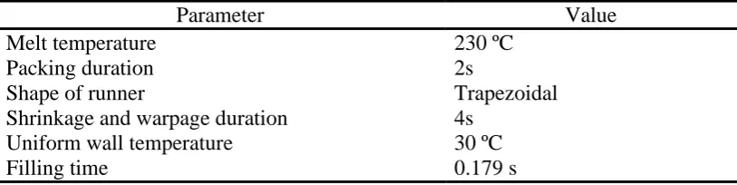
The selected product was designed by using SolidWorks and all analysis was accomplished by using Cadmould 3D-F software . Three factors were considered in this case study which, were runner system, gating system and number of cavity. The initial processing parameters that have been used during simulation were stated in Table 1.
Table 1. Initial Processing Parameters for Injection Moulding Simulation.
Parameter Value
Melt temperature 230 ºC
Packing duration 2s
Shape of runner Trapezoidal
Shrinkage and warpage duration 4s Uniform wall temperature 30 ºC
Filling time 0.179 s
The runner systems convey the melted plastic from the sprue to the gate or part. They are various geometry can use in runner such as full round, half round and trapezoid. Full round and trapezoid shape is recommended in various moulds. Half round runners are not recommended because of their low volume to surface ratio (Menges et al. 2001). In this research, trapezoid runner was selectedas a runner system. The runner size description was displayed in Figure 1.
Test 1 Test 2
a (mm) b (mm) a (mm) b (mm)
[image:3.595.87.494.223.325.2]2.25 1.25 1.75 0.75
Figure 1. Runner size test description.
The gates were used to limit the flow of melted plastic in the mould. The gate must allow melted plastic to flow and fill the cavity easily. The gate types depend on part shape, mould layout and mould systems. The examples of gate types are direct gate, side gate, tab gate, film gate, fan gate, disc gate and pin gate. In this project, a fan or edge gate was chosen as the suitable gate type. It is a common gate located in the sidewall of the part to prevent restriction of resin flow, normally used with multi-cavity; two-plate moulds (Menges et al. 2001). This project use multi-cavities mould as another factors that affecting the quality of the injected mould test samples.
In terms of gate location, it is important to understand that the molecules of molten polymer flows from thin section to thick section, therefore the gate should be located at the thick section to allow the compression of polymer molecules. The fluctuation of molecules size should be avoided, since it was one of the major causes of stress in polymer solidification (Bryce, 1996). The gate location and the cavity features were displayed in Figure 2.
a
4
Design 1 Design 2 Design 3
One cavity and the gate location at the hinges of
product.
Two cavities and the gate location at the middle edge
of product.
Three cavities and the gate location at the end of
[image:4.595.80.517.84.275.2]product.
Figure 2. Types of mould design based on number of cavity and gate location.
RESULTS AND DISCUSSION
Runner Size Analysis
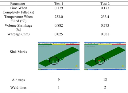
This analysis consists of two tests that have been carried out for two different runner sizes. Results of runner analysis for Test 1 and 2 were displayed in Table 2.
Table 2. Result of runner analysis for Test 1 and 2
Parameter Test 1 Test 2
Time When Completely Filled (s)
0.179 0.173
Temperature When Filled (°C)
232.0 233.4
Volume Shrinkage (%)
0.882 0.773
Warpage (mm) 0.025 0.031
Sink Marks
Air traps 9 13
[image:4.595.81.499.433.737.2]5
The first test used the larger runner and the second test by using the smaller runner. The result shows that the smaller runner (Test 2) takes 0.173s when it was completely filled, while the larger runner (Test 1) takes about 0.179s. In the other hand, the temperature when the molten polymer filled in the mould for Test 1 is lower than the temperature for Test 2.
As for the quality evaluation, the volume shrinkage for Test 1 is higher than Test 2, but the shrinkage value for Test 1 is lower than Test 2. The larger runner (Test 1) produces only a small sink marks as compared with the smaller runner (Test 2). This condition happens due to the molten plastic was good in flow condition. Therefore sink marks can be avoided. As for number of air traps, Test 1 produce less air traps which is only 9 as compared with Test 2 that produces 13 air traps. In terms of weld-line, Test 1 produced better number of line which is only 1, whereby Test 2 produced 2 weld-lines. Since quality issues are much more important than the processing conditions, therefore the larger runner size (Test 1) was chosen as the best runner size.
Gate Location and Number of Cavity Analysis
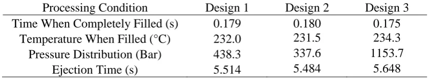
[image:5.595.82.500.446.523.2]This analysis was conducted to evaluate the best design for a mould which was consisting of an integral hinge test sample. Table 3 shows that the comparison of processing conditions based on each design. It shows that the design of 2 cavities produced good results because it has lower temperature when filled, lower pressure distribution and the fastest ejection time. However, the main evaluation depends on the quality evaluation.
Table 3: Result of Processing Conditions based on each design.
Processing Condition Design 1 Design 2 Design 3 Time When Completely Filled (s) 0.179 0.180 0.175
Temperature When Filled (°C) 232.0 231.5 234.3 Pressure Distribution (Bar) 438.3 337.6 1153.7
Ejection Time (s) 5.514 5.484 5.648
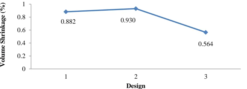
However, the quality of the test sample is much more important in this project. The quality characteristic for this project is “Smaller is better”, whereby the smaller value indicates the part have a better quality. Figure 3 shows the volume shrinkage percentage versus design. Design 3 produces 0.564% of volume shrinkage, which is the best value among the design. In term of warpage, Design 1 has the least warpage with the value if 0.025 mm. Design 3 in the other hand produced the worst warpage with the value of 0.148. Figure 4 shows the trends of warpage based on the selected design.
6
[image:6.595.115.523.318.469.2]Figure 3. Volume Shrinkage (%) versus Design
Figure 4. Warpage (mm) of test samples versus Design
Design 1 Design 2 Design 3
Number of Air Traps : 9 Number of Air Traps : 19 Number of Air Traps : 30
Figure 5: Air traps defects base on number of cavities.
Based on Figure 6, Design 1 produced only 1 line. To minimize the weld-lines, the low speed is needed. The design of 3 cavities with gate location at the end of product will be produce more weld-lines because the design has 3 gates. The number and location of gate are very important to reduce the defect such as weld-lines. Another method to minimize the effect of weld-line is to use the Flow Analysis Network (FAN)
0.882 0.930
0.564
0 0.2 0.4 0.6 0.8 1
1 2 3
V
ol
ume
Sh
ri
nk
age
(%
)
Design
0.025
0.068
0.148
0 0.02 0.04 0.06 0.08 0.1 0.12 0.14 0.16
1 2 3
Warpage
(m
m
)
[image:6.595.79.515.524.657.2]7
method, whereby this method is applicable to relatively narrow gap cavities of any shape. It permits the computation of the advancing front of melt at any time, as well as prediction of weld‐line location (Broyer et al. 1975).
As the final outcomes, based on the quality evaluation, Design 1 was chosen as the best mould design for an integral hinge test sample. The evaluation was made base on the wrapping up of defect numbers, in terms of warpage, air traps and weld-lines. As the final result, Figure 7 shows the best design for integral hinges test sample with defects outcomes. The findings of this project will be a good guidance for the mould manufacturer in terms of designing a mould for a product which consists of integral hinges component, with minimum defects.
Design 1 Design 2 Design 3
[image:7.595.79.512.237.375.2]Number of Weld-lines: 1 Number of Weld-lines:10 Number of Weld-lines:5
Figure 6: Weld-lines defects base on number of cavities
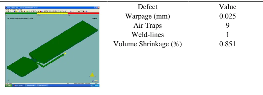
Defect Value
Warpage (mm) 0.025
Air Traps 9
Weld-lines 1
Volume Shrinkage (%) 0.851
Figure 7. The best design for integral hinges test sample with defects outcomes.
CONCLUSION
[image:7.595.82.508.422.576.2]8
brand of software such as MoldFlow, Moldex and other software for validation purposes. As for verification of this finding, it is good to fabricate the real mould and carry out the real practical injection moulding process with the same parameter setting, for comparison of findings.
ACKNOWLEDGEMENTS
The authors would like to deliver their greatest acknowledgements to the Ministry of Higher Education (MOHE) Malaysia and University Tun Hussein Onn Malaysia (UTHM) for providing the fund and facilities for this research.
REFERENCES
Beaumont, J. P., Nagel, R., and Sherman, R. 2002. Successful injection molding. Hanser Publishers.
Broyer, E., Gutfinger, C., and Tadmor, Z. 1975. A theoretical model for the cavity filling process in injection molding. Journal of Rheology, 19, 423. doi: http://dx.doi.org/10.1122/1.549379
Bryce, D.M. 1996. Plastic Injection Moulding, Manufacturing,Process, Fundamentals. Volume 1: Fundamentals of Injection Moulding Series. Society of Manufacturing Engineers.
Gordon Jr., M.J. Total Quality Process Control for Injection Molding. New Jersey: John Wiley & Sons Inc.
Groover, M.P.2011.Principles of Modern Manufacturing. SI Version. John Wiley & Sons Inc.
Koszkul,J. and Nabialek,J. 2004.Viscosity models in simulation of the filling stage of the injection moulding process. Journal of Materials Processing Technology, 157-158: 183-187.
Menges, G., Michaeli, W. and Mohren, P. 2001. How to Make Injection Moulds. Verlag: Hanser
Nardin, B., Kuzman, K. and Kampus, Z. 2002.Injection moulding simulation results as an input to the injection moulding process. Journal of Materials Processing Technology, 130-131: 310-314.
Othman, M. H., Shamsudin, S., and Sulaiman, H. 2012. The Effects of Parameter Settings on Shrinkage and Warpage in Injection Molding through Cadmould 3D-F Simulation and Taguchi Method. Applied Mechanics and Materials, 229: 2536-2540. doi:10.4028/www.scientific.net/AMM.229-231.2536
Rees, H. and Catoen, B. 2006. Selecting Injection Moulds: Weighting Cost versus Productivity. Munich: Hanser
Shamsudin, S., Hasan, S., Othman, M. H., & Rahman, M. N. A. 2012. The Effects of Injection Moulding Processing Parameters and Mould Gate Size towards
Weld-line Strength. Advanced Materials Research, 488:801-805. doi:
10.4028/www.scientific.net/AMR.488-489.801
Shen, Y.K. Wu, C. W. Yu, Y. F. and Chung, H. W. 2008. Analysis for optimal gate design of thin-walled injection molding. International Communications in Heat and Mass Transfer, 35(6):728-734
9
Tatara,R.A., Sievers, R. M. and Hierzer, V. 2006. Modeling the injection molding processing of a polypropylene closure having an integral hinge. Journal of Materials Processing Technology, 176(1-3): 200-204.