ISSN: 1992-8645 www.jatit.org E-ISSN: 1817-3195
PID IMPLEMENTATION ON REAL TIME 3-PHASE
INDUCTION MOTOR CONTROLLING AND MONITORING
1ANSAR SUYUTI, 2 INDAR CHAERAH GUNADIN., 3 NURHAYATI
1,2,3
Department of Electrical Engineering, Hasanuddin University, Indonesia E-mail: [email protected], 2 [email protected], [email protected]
ABSTRACT
This research aims to compare and determine the real time influences of tuning PID on the 3-phase induction motor real time using INFOU SCADA and monitor the alterations of frequency, current, voltage and power as well using PQM II. Tuning PID determination based on trial and error method then the curve were displayed on INFOU SCADA and motor data were showed from PQM II. The results of this research are the great influences of PID controller on induction motor. The composite of controlling P, I, and D is able to improve the time rise and offset level. By setting the valu of SV on 1500 rpm and PID value, such as P = 1, I = 10, and D = 0, the motor response displayed on INFOU SCADA graphic was good where time for PV to get SV was fast enough 11 seconds. While motor data monitored on PQM panel showed optimum speed of motor and did not exceed motor capacity that is on its name plate. Frequency, current, voltage and active power were 50 Hz, 1 Ampere, 151 Volt, and 0.06 kW respectively. The effect of tuning PID on speed of 3-phase induction motor is seen on the graphic that are showed on INFOU SCADA while the other variables are seen on the INFOU SCADA and PQM II panel connected with 3-pahse induction motor.
Keywords: 3-Phase Induction Motor, PID, PQM II
1. INTRODUCTION
Production system in the industrial sector is an important issue and often becomes complex because of unintended conditions. Those conditions are caused by the bad readibility of control system on production proses. In order to obtain the desired results, while producing, the readibility of equipment must be kept.
In the operation of an electric motor , the motor speed respon is definitely desired to be constant even if load changes. This problem can be
overcome by using a system controller
proportional, integrative, and derivative (PID) which can be created on the ladder diagram KGL_WIN. It provides PID controller. The relationship between the process of controlling three-phase induction motor and the PID algorithm controller can use the system supervisory control and data acquisition (SCADA). SCADA has some fiturs like cimon, intellution fix 6.1, info_u and so on. The program used to control the three-phase induction motor is SCADA info_u. It is chosen because it easely read the motor respons. Moreover it does not need the ladder diagram.
The influences of PID controller to the three-phase induction motors, such as current, voltage, and power can be seen in the PQM II panel or the SCADA infou display. Then it simplifies the process of collecting data. Based on this reason, research about the influences of PID controller is important to be done.
Some problems that will be discussed in this paper are how to control three-phase induction motor using PID, how to determine the effect of PID on the three-phase induction motor, and how to display implementation of the PID controller on the three-phase induction motor speed.
Some studies about the implementaion of PID have done before. One of those is The Intelligent self tuning PID controller using hybrid improved particle swarm optimization for ultrasonic motor (USM). This research was done because of the complexity of the mathematical models and the characteristic changes of ultra sonic motors during operation. By using Hybrid Particle Swarm Optimization (PSO), the accuration of position and speed convergence USM can be determined.
ISSN: 1992-8645 www.jatit.org E-ISSN: 1817-3195 babies who are prematurely born so they can
survive and adapt to the outside temperature [2]. By using fuzzy algorimh in MATLAB simulation PI was also applied in order to control The switched reluctance motor (SRM). The conclusion of this research was that the fuzzy PI algorithm was reliable in a wide range of torque load profile and protecting the motor from overcurrent and overload [3].
The other research was about PID controller implementing Genetic Algorithm for voltage stability on sincronous machine. This method applys GA as the scale of input and output factor, error change, and action control from fuzzy PID controller. The result of this application is compared with the sincronous generator that was not controlled. Integral Square Error (ISE %) is used to determined the respons of sincronous machine. This research resulted in the efectivity of GFPID controller that is able to control the respon of voltage terminals, increasing respons, and decresing the steady-state error, rise time, and settling time as well. Type GFPID-2 with the gave the best transient respon compared with other types of controllers. Furthemore, ISE has striclty alleviated from 27.4 without controller until 1.076 with new controller or ISE % greatly cut down from 96,05%. The ZN tuning methode clearly prove that it has the obvoiously short settling time of relative controller.[4]
A Fuzzy Gain Porportional Integrative (FGPI) controller is used for controlling the output voltage of an AC/DC converter. In the proposed system, the converter is composed of isolated CUK power factor correction circuits those parallel-connected for increasing power capacity. For the flexibility and modularity purpose, each converter module employs an individual microcontroller to control the power converter operation and communicate among other converter modules for load current sharing. The microcontroller in each module communicates to each other via RS485 serial communication bus. To avoid the data collision on the communication bus, a synchronization signal is used to synchronize the time slot of microcontrollers in the system for sending and receiving data. The FGPI controller is used to improve dynamic response of the output voltage loop while an analog hysteresis current controller is used to control the input current of each converter. Three-250 W/module AC/DC converters are designed and built to verify the operation of the proposed system. The experimental results show that the proposed system provides fast response of the output voltage control, and that current sharing
of each module is quite good and that a high input power factor is achieved [5].
This research is different with the previous researches. It used trial and error method by comparing between its graphic for every sampling on SCADA Infou and the results of monitoring displayed on PQM II in order to get PID values that are suitable with the optimum speed of 3-phase induction motor. There are some advantages of this study. First of all, we can directy define the implementation of PID controller on motor. Second, it can monitor every alteration of motor speed, voltage, current, daya, and frequency as well. Third, we are definitely able to determine the range of each controller value (kp, ki, and kd) that affec time rise, settling time, oscilation, and overshoot on the 3-phase induction motor. And the last one, by using SCADA expected data on the 3-phase induction motor can easily know and display them on the graphics.
2. FUNDAMENTAL THEORY
2.1 Three-phase induction motor
An induction motor is an electrical machine that converts electrical energy into mechanical energy. The principals of three-phase induction motor operation: when the 3-phase AC power is supplied to the motor’s stator, magnetic field rotates with synchronous speed, ns = 120 f / p. Where ns is synchronous speed (meter/second (m/s)), f is frequency (hertz (Hz)), and p is the number of magnetic poles. The rotating magnetic field passes through the rotor conductor. So on the rotor electromotive force (emf) will be created with equation e = 4,44 f n φ. Where e is electromotive force (joule/coulomb(j/c)), f is frequency (Hz), n is number or windings, and φ is flux (Wb). Since rotor winding is close loop, it resultes in current (i). The current inside of magnetic field creates force (f) on the rotor [6].
2.2 PID Controller
PID is a controller that can correct error in order to provide stabile output. The PID system keep objects (output) standing on set value (SV) and the value on the detected object is known as present value (PV). PID controls both of them in the same value. Then the difference between SV and PV is named deviation E. Subsequently, it will give manipulate value (MV) to actuator in order to force the object going back to set value (SV). PID components consist of Proportional, Integrative, and Derivative [7].
E = SV – PV………. (1)
ISSN: 1992-8645 www.jatit.org E-ISSN: 1817-3195 E = Deviasi
SV = Set Value
PV = Present Value
MV(t) = Pout + Iout + Dout ………… (2)
Dimana :
P Kp = proportional constantan
I Ki = integrative constantan = ʃ = = Ki/s
D Kd = derivative constantan = Td
Or the general equation :
Kp+ ʃe(t)dt+Td = Kp[e(t) + +
Td ]……….. (3)
2.2.1 Characteristics of PID Controller Before the characteristics of PID controller are further explained, forms of output response that becomes targeted changes must be well known. They are showed on the picture below :
Figure 1:Kinds of Output Responses
Table 1: Characteristics of PID controller
CL Response
Rise Time
Over Shoot
Settling
Time S-S Error
Kp Decrease Increase Small
Change Decrease
Ki Decrease Increase Increase Eliminate
Kd Small
Change Decrease Decrease
Small Change
2.3 Power Quality Meter
PQM ( Power Quality Meter ) is a tool that functions to determine the quality of the motor power. it needs a PLC (Programmable Logic Control) for controlling the system.
2.4 Infou SCADA
SCADA (Supervisory Control and Data
Acquisition) is a system that gathers information or
data from field and afterward sends them to a center computer that manages and controls those data.
SCADA Infou has some advantages. Firstly it provides stabile and effective interface communication and component of graphic X active object. It enables users to design a graphic. Second, Action trigger and VB script are reliable and
flexible. And the last, it provides more than 1000 symbols on its library[8].
3. METHODOLOGY
Some items that were analzed in this research were the analysis of ladder diagram on KGL WIN and the analysis of PID design and implementation for 3-phase induction motor on SCADA Infou.
3.1 Diagram Blok
Figure 2 : Blok Diagram of controlling the speed of 3-phase induction motor using PID
Diagram Blok above includes of 1. Computer / Notebook 2. PLC LG
3. Analog I/O 4. Inverter
5. 3-phase induction motor 6. Tachogenerator
7. Power Quality Meter
Figure 3: Controlling And Monitoring 3-Phase Induction Motor
ALTERNATING CURRENT
Type: SE2662-5K
Volts : 380 V KG : 19 H.P : 1.1
Hz: 50 A : 3/2.4 RPM:
ISSN: 1992-8645 www.jatit.org E-ISSN: 1817-3195 3.1 Flow Chart
Figure 4: flow chart of controlling system
3.2 Open Loop Test
Figure 5: System Control Open Loop
[image:4.612.78.534.65.715.2]3.2 Close Loop Test
Figure 6: System Control Close Loop
4. ANALYSIS
The specifications of 3-phase induction motor used on this research :
4.1 Open Loop Test
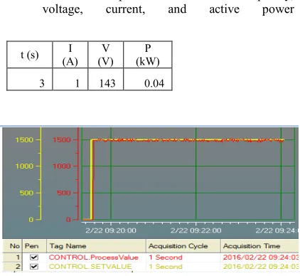
[image:4.612.315.526.172.366.2]The results of controlling and monitoring the three-phase induction motor are pointed out in the table 2.
Table 2. Data of the 3-phase induction motor frequency,
voltage, current, and active power
When numbering equations, enclose
Figure 7: Graphic of Open Loop Test
On the open loop test, the motor speed with set value (SV) 1500 rpm and frequency 50 Hz can be quickly reached by the present value (PV) The response displayed on the INFOU SCADA showed unstabile graphic, oscilation, and irregular refraction.
4.2 Close Loop Test
This research used tuning PID where KP = KI, KP > KI, KP < KI, union of KP, KI, and KD. The data of monitoring 3-phase induction motor that was got from PQM II can be seen in table 3
Table 3. Monitoring Frequency, Voltage, Current and active Power Motor Induksi 3 Fasa Pada KP =
t (s) I
(A) V (V)
P (kW)
3 1 143 0.04
PID
F (Hz)
T (s)
V (V)
I (A)
P (kW)
KP KI =1 50 6 147 1 0.06
KP KI = 10 50 17 150 1 0.06
KP KI = 100 50 7 143 1 0.05
[image:4.612.334.527.599.657.2]ISSN: 1992-8645 www.jatit.org E-ISSN: 1817-3195
Figure 8. Graphic KP = KI = 1
Figure 9. Graphic KP = KI = 10
Figure 10. Graphic KP = KI = 100
Table 4. Monitoring Frquecy, Voltage, Current, and active Power,3-phase induction motor KP < KI
PID
F (Hz)
T (s)
V (V)
I (A)
P (kW)
KP 1 KI 10 50 11 151 1 0.06
KP10 KI 100 49 175 152 1 0.08
Figure 11. Graphic KP=1 KI=10
Figure 11. Graphic KP=1 KI= 10
Figure 12. Graphic KP=10 KI= 100
Table 5. Monitoring Frquecy, Voltage, Current, and active Power,3-phase induction motor KP > KI
PID
F (Hz)
T (s)
V (V)
I (A)
P (kW)
KP 10 KI 1 50 6 151 1 0.06
KP100 KI 10 48 9 167 1 0.63
Figure 13. Graphic KP=10, KI=1
Figure 14. Grafik Nilai KP=100, KI=10
Table 6. Monitoring Frequency, Voltage, Current, and active Power,3-phase induction motor KP < KI on the KP, KI, and KD composite
PID
F (Hz)
T (s)
I (A)
V (V)
P (kW)
PID=1 50 7 1 144 0.06
P100 I1 D1 50 5 1 150 0.06
P10 I100 D1 48 274 1 154 0.06
P1 I1 D100 39 - 3 158 0.89
P100 I1 D100 38 46 4 159 0.62
P1 I100 D100 25 600 3 147 0.55
P100 I100
ISSN: 1992-8645 www.jatit.org E-ISSN: 1817-3195
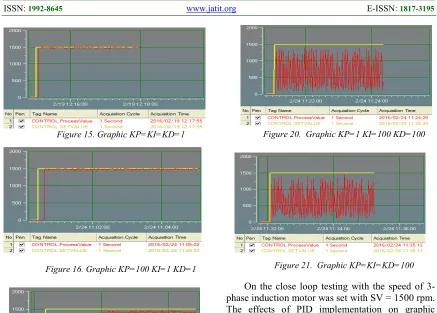
[image:6.612.87.524.73.386.2]Figure 15. Graphic KP=KI=KD=1
[image:6.612.100.290.357.712.2]Figure 16. Graphic KP=100 KI=1 KD=1
Figure 17. Graphic KP=1 KI=100 KD=1
[image:6.612.96.290.612.715.2]Figure 18. Graphic KP=1 KI=1 KD=100
Figure 19. Graphic KP=100 KI=1 KD=100
Figure 20. Graphic KP=1 KI=100 KD=100
Figure 21. Graphic KP=KI=KD=100
On the close loop testing with the speed of 3-phase induction motor was set with SV = 1500 rpm. The effects of PID implementation on graphic response, frequency, time, current, voltage, oscilation, and power are explained :
1. KP, the higher the KP value was; the higher the fequency was, the faster the speed of PV reached SV value, the higher the Power and oscilation, and the more stabile the voltage and current were. 2. KI, if KI had so high value, the frequency
would fall down, the voltage would be high, and current and power would become stabile. KI was applied to make PV rapidly getting SV value. Furthermore it could minimize the oscilation.
3. KD, if KI was more than 1, oscilation occured it could help PV to get SV value but it needed much time. The current, voltage, and power became higher but the speed of motor was not stabile.
5. CONCLUSION
Implementation of PID on the 3-phase induction motor could keep the speed of motor more stabile. It was showed on the SCADA INFOU. By the open loop test, oscilation became higher. Meanwhile on the close loop test, by setting the tuning PID on KP = 1, KI = 10 and KD = 10, oscilation could be minimized.
ISSN: 1992-8645 www.jatit.org E-ISSN: 1817-3195 improve the voltage (151 V), power (0.06 kW)
whereas on the open loop test, they were lower. Moreover frequency and current were constant on 50 Hz and 1 A respectively.
REFRENCES:
[1] Alrijadjis, Tanaka Kanya, and Nakashima Shota, “Intelligent Self-Tuning PID Controller Using Hybrid Improved Particle Swarm Optimization for Ultrasonic Motor”, Journal of Theoretical Applied Information Technology, Vol. 66, No. 1, 2014.
[2] Adhi Ksatria Theopaga, Achmad Rizal, and Erwin Susanto, “ Design and Implementation of PID Control based Baby Incubator, Journal of Theoretical Applied Information Technology, Vol. 70, No. 1. 2014.
[3] Khalid Grari, Jamal Bouchnaif, Mohammed Azizi, Hicham Fadil, and Anas Benslimane, “ Sensorless Control of Switched Reluctance Motor with Fuzzy-PI Controller”, Journal of Theoretical Applied Information Technology, Vol. 83. No. 1, 2016.
[4] Saad Mohd Sazli, Hisha,Uddin Jamaluddin and Intan Zaurah Mat Darus, “Implementation of PID Controller Tuning Using Differential Evolution and Genetic Algorithms”, International Journal of Innovative Computing Information and Control, Vol. 8, No. 11, PP 7761 – 7779, 2012.
[5] Kanthaphayao Yutthana, Viboon Chunkag and Uthen Kamnarn, “Fuzzy Gain Scheduling of PI Controller for Distributed Controll of Parallel AC/DC Converters”, International Journal of Innovative Computing Information and Control, Vol. 7, No. 12. PP 6757 – 6751, 2011.
[6] Nurhayati, “Study Pengontrolan Motor Induksi 3 Fasa menggunakan PID berbasis INFOU”, Skripsi Universitas Halu Oleo, 2013.
[7] Sumiati ruzita, “Analisis Penggunaan Motor DC
menggunakan Logika PID dengan
Mikrokontroller ATMega 8535”, Jurnal Teknik Mesin, Vol. 6 No.2, 2009.
[8] Sulasno dan Thomas Agus Prayitno, Teknik Sistem Kontrol, Yogyakarta: Graha Ilmu, 2006. [10] Gaing Zwee Lee, “A Particle Swarm
Optimization Approach for Optimum Design of PID Controller in AVR System”. IEEE Transaction On Energi Convertion, PP. 1 – 9, 2014.
[11] Setiawan Iwan, “Programmable Logic Controller ( PLC )b dan Teknik Perancangan Sistem Kontrol”, - Ed.1. – Yogyakarta : ANDI, 2007.
[12] Petruzella D. Frank, “Industrial Electronics”, Diterjemahkan oleh Sumanto, Yogyakarta: Andi, 1996.