493
DESIGN PROTOTYPE OF ROBOT EXPLORER TERRAIN
NATURAL DISASTERS FOR MAINLAND FIELD
1
GIVA ANDRIANA MUTIARA, 2GITA INDAH HAPSARI
1,2
Telkom University, Department of computer engineering, Telkom Appliance Science
E-mail: [email protected], [email protected]
ABSTRACT
Nowadays, robots are used as alternatives tool to replace human activities in various fields. The case of the evacuation of disaster victims is one of good example where robots became one of the best choice because the heavy and dangerous terrain that mostly appear at disaster area was proved to be harmful and dangerous for humans operator. The idea of using robots is to become the instrument that can be controlled remotely, over difficult terrain and provide information for the evacuation team before taking further action. The robot used is wheeled robot designed and controlled wirelessly by the joystick. Cruising terrain information gathering is done using IP camera with wireless transmission media. Camera catches are then displayed in a web application on a personal computer (PC). Tests performed include testing the servo motor, servo motor control is wireless, wireless transmission range, IP camera, transmitting streaming video, and streaming video transmission range. The test results indicate that the functionality of the motor and the camera has been in accordance with the purpose only to be enhanced wireless coverage.
Keywords: Robot explorer, field land, IP Camera, Wireless, Video Streaming
1. INTRODUCTION
In many case of a natural disaster, rescue teams often have to trace the victims in the area with difficult terrain and inaccessible by humans. An
earthquake disaster sometimes created this type of condition which requires a Search and Rescue (SAR) to find victims among rubble or rocks piles. In other cases sometimes SAR team need to find alternate ways for evacuation and need to gather more information regarding the state of the fields for minimum loss. So in this case, we need a tool that can assist or replace humans for exploring any possible harsh terrain and provide any needed information regarding circumstances and situation in the disaster area.
Robot design variation depends on its function and application.
Embedded systems are used to control the robot as part of the control hardware and mechanics, which build by using microcontroller [1]. By using the embedded system, the design engineer can perform the optimization of the size and cost of the product, and may increase the capabilities and performance of the device.[2]
The purpose of this study was to design a prototype robot that could help a rescue team by its ability to explores, records and send terrain information remotely. The robot movement will be controlled by joystick using wireless system and the information will be recorded in a form of video
format that can be accessed using web application streaming.
2. SYSTEM DESIGN AND IMPLEMENTATION
There are few parameters that must be considered for designing robot for outdoor used. First most common aspect is the environment where the robot will take its operation. Another aspect is the appearance of noise or obstacle generated by the surrounding environment which could interfere with signal transmission. [3]
To achieve the basic need for all the parameters mentioned, the prototype of the robot will have a system that has the following specifications:
1. 4 wheeled robot with a 2 DC motors on the rear wheels controlled by joystick
using wireless transmission.
Microcontroller used to control motor movements is ATMEGA 8.
2. 1 piece robot with integrated camera mounted on the top of the robot and can be routed to the left or right by using the motor. Camera used is IP Camera IC-3005WN Wireless 802.1.1n dual mode and used motor is a servo motor.
494 and transmitted wirelessly and released on a web-based application. The software used is XMPP Control Panel and Plug in. War shark software used to test the parameters of delay on streaming video. 4. For wireless control the Robot designed to
have power supply from a 9 Volt batteries.
Figure 1 describes the design of the overall system prototype robot natural disasters which consists of 2 parts:
1. Mechanical and mechanical control module 2. Camera module and video streaming
applications
Figure 1: Design of Robot System Natural Disaster
Mechanical and control module is a module that handles all motors and mechanic movement of the robot using a joystick for its input.Camera module and video streaming application is a module that handles video capture on camera and display it in a web base application form.
Figure 2: Module mechanics and mechanical control
In Figure 2, the keystrokes of a mechanical joystick on the control module generate an electrical signal that activates a specific channel and then forwarded to transmitter circuit. The transmitter circuit changes this signal to data signal and sends it using wireless media. After this data signal received by the receiver in the robot, it
convert to an electrical signal, and forwarded to the microcontroller. Transmitter and receiver have using the frequency of 27 MHz and 40MHz. Microcontroller then process the data signal and convert it into a control signal for motor movement. Figure 3 describe the flowchart for this function. The output of the receiver connected to port C as input. Each different keystrokes will activate different channels so that data is transmitted and received by the receiver will produce a different movement.
The command set for robot movements consists of two groups of movements. Four body movements for the DC motor at the rear wheels which include forward motion, backward, right and left. Two servo motors movements for camera which include left and right rotation.
Figure 3: Flowchart for motor movements
The microcontroller used for processing the data in the receiver circuit is ATMEGA 8 from ATMEL
co.
The programming software is C
odeVision AVR microcontroller (CV-AVR) and programmed by using the C programming language. Figure 4 shows the mechanical build of the robot.
495 recording device that has the ability to process audio as well as visual which could accessible to PCs directly, or through LAN, internet , and mobile phone networks. The camera module handles IP address configuration and streaming video data to be sent over the Internet
Figure 4 : The Prototype of Robot explorer Terrain [4]
The application for video streaming modules is built on laptop via a web browser using the IP address. Applications built using web-based program for more dynamic and portable use. Flowchart in Figure 6 shows the application consists of two parts: the client and admin.
Figure 5 : Camera module and streaming camera
At user client interface in Figure 7, there are several tabs menu that could be accessed by user. The home menu leads to streaming video visualization of road / terrain that traversed by the robot. In the image menu, the user can view the captured images and video recordings that are controlled by the admin. In the user interface admin, admin can change the password, recording images and videos as well as view and delete the data record.
Interface Web Browser
Camera Active?
Capture Picture/ Video?
Yes
Picture Yes
Video No
Ambil gambar
Picture Capture
Picture Storage
See Picture Delete ?
Delete Picture Yes
Show Picture Ya
Video Capture
Save
Video Storage
Watch Video
Video Show
Ya
Delete ?
Delete Video
Yes Start
End Interface User
Active
No No
No No
Yes
No No
Gambar 6 : Flowchart for User Interface Application[5]
496
3. HARDWARE AND SOFTWARE DESCRIPTION
3.1 Microcontroller AVR ATMEGA 8
AVR is a series of 8-bit CMOS microcontroller Atmel artificial, based on RISC architecture (Reduced Instruction Set Computer). The features of the AVR microcontroller ATmega8 are as follows [6]:
1. Maximum clock frequency at 16 MHz. 2. 32 ports I/O channels in 4 groups: port A,
port B, port C, and port D.
3. 10 bits of Analogue to Digital Converter (ADC) with 8 inputs.
4. 3 Timer/counters.
5. 8 bit CPU with 32 registers.
6. Watchdog timer with internal oscillator. 7. SRAM internal: 1K byte.
8. 16K byte flash memory read while writes. 9. Interrupt internal & externals.
10. Communication Port SPI EEPROM (Electrically Erasable Programmable Read Only Memory) : 512 byte.
11. Analogue Comparator. 12. 2.5 Mbps Serial USART.
3.2 IP Camera
IP Camera is a technology was developed to maintaining security and monitoring a room or space. IP camera is a CCTV (Closed-Circuit television) cameras use Internet Protocol to transmit image data and control signals over Fast Ethernet links.. A number of IP cameras are usually placed together with a Digital Video Recorder (DVR) or Network Video Recorder (NVR) to a video surveillance system.
3.3 DC Motor and Servo Motor
Servo motors are DC motors which have high quality, already equipped with control systems in it. Servo motor applications are often used as a closed-loop control to handle the change in position precisely and accurately and also have speed and acceleration settings. Servo motor cabling system consists of three parts, namely Vcc, Gnd, and Control (PWM).The use of PWM at servo motor is different with the use at DC motors. In the case of servo motor, giving values to the PWM will make the servo motor moves in a certain position and then stopped (control position). Settings can be performed by using delay on any displacement of the starting position into the end position.
There are two type of Servo motors: continuous servo motors and un continues servo motors.
Continuous servo motor can rotate a full 360 degree allowing it to perform rotational motion.
3.4 Programming Language
Code Vision AVR is a software C-cross compiler, using C language for writing its program codes. Code Vision AVR has complete IDE (Integrated Development Environment), where programming, compiling, manufacturing of machine code (assembler) and downloading the program into the AVR chip can be performed on Code Vision. It has terminal facility to perform serial communication with programmed microcontroller.
4. TESTING AND ANALYSIS
Whole system testing performed on two phases, module test and integrated test.Module test is done by testing the functionality of each module while the integrated testing done by integrating both the module and test the performance and functionality of a system prototype robotic rover field of natural disasters.
4.1 Module Test
The test of mechanical modules consists of motor movement test and wireless coverage test. The motor movement test is done by connecting all the devices on the mechanical module and mechanical control and observes the synchronization between motor movements and key stroke on the joystick. Test result in Table 1 show that the control module could function well.
Table 1: Motor Control Movement Test Result
No Push
Button
Movement
1 Forward Move Forward (rotates clockwise on both DC motor)
2 Backward Move Backward (rotates counter
clockwise on both DC motor) 3 Turn Left Move Forward (rotates clockwise on
right DC motor)
4 Turn Right Move Forward (rotates clockwise on left DC motor)
5 Camera
Look Right
Rotate Right (rotates clockwise servo motor)
6 Camera
Look Left
Rotate Left (rotates counterclockwise servo motor)
497 signal amplification to increase the coverage of the wireless signal.
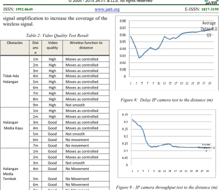
Table 2: Video Quality Test Result
Obstacles Dist anc e
Video quality
Wireless function to distance
1m High Moves as controlled
2m High Moves as controlled
3m High Moves as controlled
Tidak Ada 4m High Moves as controlled
Halangan 5m High Moves as controlled
6m High Moves as controlled
7m High Moves as controlled
8m High Moves as controlled
9m High Not smooth
1m High Moves as controlled
2m High Moves as controlled
Halangan 3m Good Moves as controlled
Media Kayu 4m Good Moves as controlled
5m Good Not smooth
6m Good No movement
7m Good No movement
1m Good Moves as controlled
2m Good Moves as controlled
3m Good Not smooth
Halangan 4m Good No Movement
Media
Tembok 5m Good No Movement
6m Good No Movement
7m Good No Movement
Camera module test performed by testing the quality and streaming range of the video based on delay and throughput parameters. Tests range of streaming delivery is done by measuring the quality of the resulting video on the application based on distance and obstacles.
Video streaming application module test performed by checking the compatibility of the application programs with various web browsers and also test its functionality. In addition it also conducted the testing range on the streaming delivery of video quality based on the distance the prototype robot with the user.
Test results in Table 2 shows that video quality does affected by distance and obstructions. The farther the distance between the user laptop and the camera will lower the quality of the video. The data also shows that video quality also affected by the obstacles that appear between user laptop and the camera.
[image:5.612.84.522.63.443.2]Figure 8: Delay IP camera test to the distance (m)
Figure 9 : IP camera throughput test to the distance (m)
Video quality testing performed on delay and throughput parameters using the software Wireshark. From the test results in Figure 8 and 9 demonstrated that the greater the distance the delay will be longer and bandwidth that occurs will be smaller.
4.2 Integrated Testing
[image:5.612.89.341.112.448.2]498
Tabel 4 : Movement test on a variety of terrain [4]
No Terrain Movement Notes
1 Sandy Soil Mainland Smooth Succeed
2 Gravel land Not smooth Skid Tires
3 Bumpy Ground Not Smooth Hiccough
4 Slick surface Not Smooth Skid Tires
5 Pool of Water (3cm) Smooth Succeed
The quality of video test provides the similar outcome as the camera module test which means that video quality would be lower for at farther distance. The test limited to the distance of 9 meters due to the limit of controlling signal for control module and show that the video quality still displayed properly on the web application within this distance.
5. CONCLUSION
Prototype Robot cruising terrain natural disasters that are designed and implemented have the functionality to suit the purpose that it can take the difficult terrain roaming and can provide information in the form of streaming video over the internet. Mechanical module can function properly in accordance with the given control via a joystick. Only upon passing cruise uneven terrain, the robot runs less smoothly. This can be done by adding the motors on the front wheels. Part transmitter and receiver work well in handling wireless delivery. Only wireless coverage achieved is less good so the need for signal amplification in order to reach its maximum coverage area. The control module is functioning at its best when there are no obstacles between the robot and the control joystick. IP Camera functions properly and can provide images with good enough quality in the range of wireless coverage.
REFERENCES:
[1] Ramya, V., Palaniappan, B., “Web Based Embedded Robot For Safety and Security Application Using Zigbee”, International Journal of Wireless&Mobile Network (IJWMN), 4(6), 2012, pp 155-174
[2] Siagian, C., Chang, C, K., Itti, L., “Mobile Robot Navigation System in Outdoor Pedestrian Environtment Using Vision Based Road Recognition”.
[3] Roberts, R., et. Al., “Learning Outdoor Mobile Robot Behaviour By Example”, Center for robotics and Intelligent Machines Georgia Tech Atlanta
[4] Hartoko, Motor Design for Robotic Explorers Natural Disasters, 2013, Telkom University [5] Fatra Yudis Epri Pratomo, Visual Sensing
Robot With IP Address, Telkom University [6] Gadre, Dhananjay V, Programming and
Customizing The AVR Microcontroller, 2000. Mc Graw Hill, New York
[7] Teguh Iman Raharjo, Design and Implementation of wireless communication system on the robot explorers natural disasters, Telkom University
[8] Fauzy, R.R., Sistem Pengendali Robot Mobil berbasis Mikrokontroler ATMEGA16 dengan Antar Muka RJ45, 1(1), Halaman 9
[9] Schuler, McNamee, Industrial Electronic and Robotic 1986, McGraw Hill, New York [10]V. Ramya, B. Palaniappan, and Subash