DESIGN IMPROVEMENT OF FIXABLE CLAMPING JIG FOR MILLING
MACHINE BASED ON SURFACE ROUGHNESS
N. Ab Wahab
1, AziziArif Bin Onn
1, Abdul Khahar Bin Nordin
1, M. Zahari
2, N. Abd Mutalib
2, R. Mohd Nor
2and N. Syuhada Nasir
11
Faculty of Mechanical and Manufacturing Engineering Technology, Universiti Teknikal Malaysia Melaka, Hang Tuah Jaya, Durian Tunggal, Melaka, Malaysia
2
Faculty of Electric and Electronic Engineering Technology, Universiti Teknikal Malaysia Melaka, Hang Tuah Jaya, Durian Tunggal, Melaka, Malaysia
E-Mail: [email protected]
ABSTRACT
Jigs provide a means of manufacturing interchangeable parts since they establish a relation with predetermined tolerances, between the work and the cutting tool. Jigs are used on drilling, reaming, tapping, milling and tapping. The objective of this project is optimizing and analyse of the fixable clamping jig for milling machine. The method is modified clamp mechanism of the previous jig, optimize the design of the fixable clamping jig for milling machine, and analyse the result of fixable clamping jig in term of surface roughness. The result of the experiment will be evaluated base of surface roughness by using Portable Surface Roughness Tester, SJ-401. Then, the result will compare with current vise result and fixable clamping result. From the results that have get, the average of Ra value using current vise as a clamping method is higher than using fixable clamping as a clamping method which are 3.468 when using current vise and 1.657 when using fixable clamping for Delrin as a work piece. While for aluminum as a work piece, the average of Ra value using current vise as a clamping method is lower than using fixable clamping as a clamping method using current vise is 3.069 compared to using flexible clamping is 5.908.
Keywords: milling, fixable clamping, work piece, jig, surface roughness.
INTRODUCTION
Mass production of work-piece is based on the concept of interchangeability according to which every part produced within an established tolerance. Jigs provide a means of manufacturing interchangeable parts since they establish a relation with predetermined tolerances, between the work and the cutting tool. Once the jig is properly set up, any number of duplicate parts may be readily produced without additional set up .Although jig methods have also advanced considerably, the basic principles of clamping and locating are still the same especially milling machine. Jigs are used on drilling, reaming, tapping, milling and tapping. There are many advantages for using jigs in production. Jigs eliminate individual making, positioning and frequent checking. This reduces operation time and increase productivity.
The fixture designing and developed is well-thought-out as complex process that demands the understanding of dissimilar areas, such as geometry, tolerances, dimensions, procedures and manufacturing processes. While designing this work, a better number of literature and titles written on the subject by well-known authors are bring up. All outcomes and conclusions gained from the literature review and the interaction with fixture designers are used as guide to design the current research work. (Goutham.N and Ramesh Babu.K, 2007).
While, the operations that often used by a manufacturer in a milling machine is face milling, end milling, slotting, thread milling, plain milling and side milling, etc (Vukelic et al., 2012).
Most of the industries are using the milling machine to produce the die, aerospace, automotive and
machining operation, most of the individual trained by convectional milling machine before they use the CNC milling machine.
The problem that have at previous jig show that the angle of the clamping has some error which is lifted up 4-degree error of clamp for this problem, the result for the clamped product and quality of the product will be reduce. Second problem from the previous jig is the thickness of the base jig. The base of the jig is too thick which is 50 mm When the thickness is high the weight of the jig will be increase and make the jig difficult to remove to another machine. The cost for making the jig also will be lower.
The clamping of this machine also has its own weakness which is only limited surface of the work-piece can be cut in one clamp. This can increase the time setup of the clamping during machining process. Hence, this flexible clamping was developed and the objectives are:
a) To modified clamp mechanism of the previous jig. b) To optimize the design of the fixable clamping jig for
milling machine.
c) To analyse the result of fixable clamping jig in term of force.
RESEARCH METHODOLOGY
Figure-1. System development life cycle (SDLC) of the project.
A. Optimization of design Part 1 (clamping vice)
In this stage, previous jig show that the angle of the clamping has some error which is lifted up 4-degree error of clamp for this problem, the clamp mechanism will be chance from the previous jig.
Next, a sketch of the product is drawn to solve the problem statement. Then, the sketch is re-draw by using Solidwork software. Figure-2 shows the final expected product to be process.
Figure-2. New design clamping vice using Solidwork.
Part 2 (Base)
Second problem from the previous jig is the thickness of the base jig. The base of the jig is too thick which is 50 mm. When the thickness is high the weight of the jig will be increase, so to reduce the weight, the thickness will be reduced to 35 mm.
Next, a sketch of the improvement product is drawn to solve the problem statement. The sketch is redrawing by using Solidwork software. Figure-3 shows the final expected product to be process.
Figure-3. New base part design.
B. Optimization of the result
The previous thesis, the result was evaluated base on the surface roughness of the material that use the jig. The dry cutting condition was used for this project because it is a milling process where as the liquid is not used during the machining process.
C. Analyse of the result
The last objective for optimize and analyse of the fixable clamping jig for milling machine state that to analyse experiment result base on surface roughness of the work pieces.
To analyse the result, the experiment will be done by using Portable Surface Roughness Tester, SJ-401.
There are two types of material is used in this testing which is aluminium and Delrin.
The result for surface roughness will analyse using statistical method which is take arithmetic mean surface roughness.
RESULT AND DISCUSSIONS
Figure-4 below shown fixable clamping that have been optimize after go through all machining process that has planned before. The fixable clamping function well and the problem have been optimized.
Figure-4. Fixable clamping.
Optimization product and process (Base Part)
In this part, the changes are in its shape and use one material to make this base as shown in Figure-6 below. It is because the base part in the previous clamping is use two part. So, the usage of the material is higher and the cost also increase. Process for making the previous base is too many and time to make it is long and increase cost.
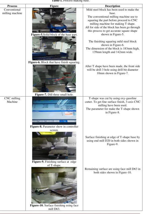
Table-1. Process making base.
Process Figure Description
Conventional milling machine
Figure-5.Solid block of the base part.
Figure-6. Block that have finish squaring.
Figure-7. Dill three small hole.
Mild steel block has been used to make the base.
The conventional milling machine use to squaring the part before proceed to CNC milling machine for making T shape. All for side of the block has been go through
this process to get accurate square shape shown in Figure-5.
The finishing squaring mild steel block shown in Figure-6.
The dimension of the block is 183mm high, 139mm length and 142mm wide.
After T shape have been made, the front side will be drill 3 hole using drill bit diameter
10mm shown in Figure-7.
CNC milling Machine
Figure-8. Parameter show in controller screen.
Figure-9. Finishing surface at edge of T-shape.
Figure-10. Surface finishing using face mill D63.
T-shape was cut by using oxy-gasoline cutter. To get fine surface finish, 3-axis CNC
milling have been used.
The parameter for make the T-shape shown in Figure-8.
Surface finishing at edge of T-shape base by using end mill D20 in both sides shown in
Figure-9.
(Clamp Part)
All the part in clamping vise are using conventional milling machine. The process that have been use are squaring, slotting and pocketing. The part in the clamping vise that have been changing and making improvement are clamp jaw and beam of the vise. The clamping jaw have been change shown in Figure-13.
Figure-11.Clamping jaw improvement.
For the beam of the vise have improve from previous beam shown in Figure-12 by go through slotting process to make the clamping vise can attach with the beam of the vise. Slotting process have been using end mill D10.
Figure-12. New beam of vice.
(Full assemble finish part)
After the clamping part was assembled, clamping part and base was assembled each other by inserting the pin and nut at the clamping part into the base part. Next, the rod at the base part was move into the clamping part until both assembled parts was tightened as shown in Figure-13.
DISCUSSIONS
During the process making the product, that have some problem occur and the change of the design and the diameter of the part. The part that have go through improvement from the planning before is clamp vise and add nut at the rod.
The nut was put at the rod for lock the rotation on any degree. This solution occur for the problem for miscalculate for the drill D10 to D11at 3 point shown in
Whennut not be add at the rod, the vice will be vibrate and effect the surface finish of the work piece because the gap between lock pin and pin hole. Lock add with the rod to lock the rotation can be refer in Figure-15.
Figure-13. Assemble of finish product.
The other problem that have been face in the product after do the machining by doing tapping process is the thread of the screw not reaching area in the end of the hole shown in Figure-16. This finding was unexpected and the problem cause for human error and parallax error because during tapping process the hand not perpendicular to the surface of the base. So, the clamping vice not parallel to the base and cause surface machining have different depth but this problem can be overcome by doing squaring by using this jig.
For initial planning, that the two-analysis process for analyse the product which are product force by using dynamometer and surface roughness. But the analysis process that have been done is surface roughness only. This problem occurs because of the limited time for produce the product.
Figure-15. Nut place at rod.
Figure-16. Tapping process problem.
Table-2. Comparison of Ra value (Delrinas a workpiece).
Reading
Ra value using current
vise
Ra value using fixable clamping
1 3.134 2.174
2 3.728 1.793
3 3.093 1.530
4 3.434 1.592
5 3.544 1.745
6 3.912 1.656
7 3.428 1.112
Average 3.468 1.657
Table-2 shown that the average of Ra value using current vise as a clamping method is higher than using fixable clamping as a clamping method which are 3.468 when using current vise and 1.657 when using fixable clamping. This proves that fixable clamping can be used as a clamping method due to its surface finish is better than using current vise.
Table-3. Comparison of Ra value (Aluminum as a work piece).
Reading Ra value using current vise
Ra value using flexible clamping
1 3.227 6.317
2 1.655 4.216
3 3.319 5.703
4 2.875 5.961
5 2.866 7.374
6 4.815 5.959
7 2.724 5.829
Average 3.069 5.908
Table-3 shown that the average of Ra value using current vise as a clamping method is lower than using fixable clamping as a clamping method using current vise is 3.069 compared to using flexible clamping is 5.908. This proves that the surface finish when using current vise is better than using fixable clamping as a clamping method.
CONCLUSIONS
accomplished, the outcomes demonstrated that Ra value by using fixable clamping is lower than current vice clamp when the work piece is Delrin. While, when the work piece is aluminium, the Ra value for current vice clamp is lower than fixable clamping. This demonstrates the unbending nature of fixable isn't useful for hard material contrasted with delicate material, for example, Delrin.
ACKNOWLEDGEMENT
The authors would like to thank Faculty of Manufacturing Engineering, Faculty of Mechanical, Mechanical and Manufacturing Engineering Technology and Universiti Teknikal Malaysia Melaka (UTeM) for their support that enabled this work to be carried out through the grant of FRGS/2018/FTKMP-AMC/F00387.
REFERENCES
[1] Altin A. 2014. The Effect of the Cutting Speed on the Cutting Forces and Surface Finish When Milling Chromium 210 cr12 Steel Hard facings with Uncoated Cutting Tools. Materiali in Tehnologije. 48(3): 373-378.
[2] Vukelic D., Tadic B., Miljanic D., Budak I., Todorovic P. M.& Randjelovic S. 2012. Novel workpiece clamping method for increased machining performance. Tehnički Vjesnik. 19(4): 837-84.
[3] N.B. Ab Wahab et al. 2017. Development of fixable
rotation clamping method for milling machine. Proceedings of Mechanical Engineering Research Day 2017, 109-110.
[4] N. Ab Wahab et al. 2018. Design and Development of