5848
THE DEVELOPMENT OF INTELLIGENT SYSTEMS FOR
SOLAR PANELS STATION AND METHODS FOR
DETERMINING THE PRECISION OF THE SOFTWARE
TRACKING SYSTEMS , THE USE OF WIRELESS
COMMUNICATION DEVICE
SATYBALDIYEVA F.A1*., BEYSEMBEKOVA R.N1., SARYBAEV A.S2.,ESENBEKOVA G.J3.,
1Kazakh National Research Technical University named after K.I.Satpayev 2 M. Auezov South Kazakhstan State University
3 T.K. Zhurgenov Kazakh National Academy of arts
*Corresponding author’s e-mail: [email protected]
ABSTRACT
Use of wireless communication between detectors, transducers and industrial logical controllers in modern optical SPS heliostat control systems is more advantageous than laying hundreds meters of cable.
To provide power supply, it is proposed to equip each heliostat with a self-contained power supply, since heliostat operates when concentrated solar radiation in the receiver is sufficient for steam generation, while the rest of the time it is in the standby mode. That is why use of a solar battery-powered self-contained power supply is more advantageous than use of centralized power supply from the industrial network. As distinct from other measuring informational systems, the described heliostat control system operates only when tracking parameters deviate towards the maximum permitted values.
Presented in article the model of system of automatic control of the heliostats constitutes one of the varieties of measurement and information and control systems. Unlike other measurement systems described control system of the heliostats works only when the deviation of the tracking parameters in the direction of the maximum. The use of modern control systems, heliostats optical system SES wireless connections between sensors, transducers and industrial logic controllers is advantageous compared to laying hundreds of meters of cables.
Key words: Intelligent Control Systems, Mathematical Model,, Heliostat, Wireless Communication, Power Supply.
1 INTRODUCTION
Interest in alternative energy sources was the highest in the world in connection with the growing needs of the global economy in energy, limited reserves of hydrocarbon resources has exacerbated the problem of the use of renewable sources. Development of renewable energy sources provides environmental and energy security, environment preservation, clean, preservation of hydrocarbon reserves for future generations and the possibility of their use for other non-energy purposes. The main obstacle in the development of renewable energy sources is the high specific capital costs and, consequently, high tariffs for electricity. However, rising prices for electricity produced in the traditional way, the decline in the price of energy from alternative
5849 a serious threat to the existence of future generations. Inefficient use of energy is accelerating the depletion of natural resources, which negatively affects the completion of state revenues that could be used for social needs and infrastructure development
Solar cells were invented and then developed in 1960’s as power provider in space use. It received focus in 1970’s oil crisis in seeking alternative energy sources. Rapidly, the solar cells’ advantage of remote use was highly recognized, and in turn, it promoted the development of the whole photovoltaic industry. The solar cell record efficiency increased, and a silicon cell reached up to 20% efficiency milestone in 1985. In the next decade, a 15% to 20% steady growth rate
was seen of the photovoltaic industry, and reached a 38% in 1997 . Meanwhile an exponential increase of annual solar power installation has been experienced [1]. Currently, the semiconductor materials mostly used are monocrystalline silicon, polycrystalline silicon, amorphous silicon and cadmium telluride, where crystalline silicon PV systems together have more than 85% of today’s market share and thin film technologies (such as CdTe and amorphous silicon) takes most of the rest [1]. The major problem hinders solar cells electricity market share is that solar cell generated electricity lacks economic grid parity with market price. The problem is temporarily addressed by government subsidy and tariff programs, but, the thesis author expects it must eventually be resolved by the technology itself. The Leveled Cost of Electricity (LCOE) is the net present value of total life cycle costs of the project divided by the quantity of energy produced over the system life . Ways to reduce LCOE may be increasing efficiency including good maintenance, reducing cost and lengthening solar cell working lives. One of the ways to increase efficiency is the use of devices and automation devices that collect radiation from continuous tracking of the Sun, increasing the output power and thereby creating an intelligent system for controlling and controlling the elements of the solar panels.
Existing solar energy systems are still very expensive compared to traditional methods of electricity production, due to the material of semiconductors, which are made of PV solar cells (solar cells). Analysis and study of minimizing the prices of PV solar systems show
that the best way is to concentrate the sun's rays. Solar concentrating PV system also require optimization of rates so it is very important to optimize the parameters of solar concentrating PV energy systems, particularly coal misalignment of panels which can be used to create cost-effective solar PV system.
There are several types of support-rotary mechanism (PSM) which distinguishes between a design:
PSM type azimuth (slewing rings rotational movement horizontally;
PSM moves progressively horizontally); PSM the type elevation (OPU with the rotational movement vertically;
Slewing rings in reciprocating vertical); PSM the type of azimuth-elevation (OPU rotating horizontally and vertically;
PSM rotary motion horizontal and reciprocating vertically;
PSM translational movement vertically and horizontally)[2].
The system of tracking the movement of the Sun can be divided into three classes:
A system of tracking the Sun's motion on the basis of sensors (light sensors, image sensors, video cameras);
A system of tracking the Sun's motion on the basis of the calculation of coordinates of the position of the Sun in the celestial sphere by the astronomical calendar;
A tracking system positioning.
The objective of accuracy determination in tracking software systems (TSS), just as in optical tracking systems (OTS), is to determine the misalignment angle between the Sun and the optical axis in concentrators or the set direction of reflection in heliostats.
5850 operates as follows. The control program calculates the Sun's angular position in a coordinate system associated with a concentrator (or heliostat) — the Sun's angular coordinates are determined, based on which the software determines the angles of heliostat turning (the angles of concentrator turning are equal to the Sun's angular coordinates in one CS), the drives receive a signal for handling of these angles. That is, TSS cannot “see” the Sun, and thus there is no compensation of drive errors and rotational axes and, accordingly, control algorithm errors. But here we also obviously need control of concentrator turning angles, i.e. feedback is required as well. This task was considered and solved in the course of development of the Big Solar Furnace (BSF) heliostat software control system; the azimuthal and zenithal drive reducers were equipped with angular sensors at a pitch of about 36 arcsec.
2 THEORY AND CALCULATIONS
As is known, solar cell concentrators (heliostats) must turn (keep track) of the Sun with a certain level of accuracy due to its appar-ent movemappar-ent.
At the initial approximation, the defo-cusing leads to a shift of a concentrated spot at the receiver. The methodical task setting (con-cepts of static and dynamic defocusing modes), as well as experimental and calculation studies of the influence of defocusing, virtually the only ones to the present day, were conducted in [2-5]. In these studies, allowed values for defocusing angles were identified for energy concentra-tors. It was found that must not exceed 16
arcmin at the acceptable flow reduction at the
re-ceiver by 10% for concentrators of solar power plants. At that, along with concentrator’s accura-cy characteristics, tracking accuraaccura-cy is one of the factors influencing the solar radiation concentra-tion, i.e. irradiance variation in the focus and mean concentrations at the receiver. Tracking accuracy, as was determined above, is clearly de-fined by a defocusing angle or by an angular deviation of axial solar beams from either optical axis of the concentrator (the concentrator mode) or predetermined direction of solar beam reflec-tion from the heliostat (the heliostat mode). The issue of permissible defocusing angles also be-comes relevant due to problems of development of software systems for concentrators (heliostats) to keep track of the Sun. Acceptable values of defocusing angles obtained in [2-5] generally
al-low to make the conclusion on possible require-ments for the tracking accuracy, although during the design of tracking systems it is still assumed that the tracking accuracy must not exceed 1
arcmin.
Flow densities at the receiver’s surface elements and subsequently flows will be deter-mined using the model suggested by Grilikhes V.A. [3]. This model assumes that even if beams are reflected from a non-precise concentrator, the angular dimension of the reflected solar cone will not change; and that concentrator inaccura-cies are distributed according to some randomly set rule with the standard angular deviation of normal in relation to normal of a precise concen-trator. In practice, this integral is defined numer-ically and actually is replaced by a sum of the following type. For example, when determining the flow on the area SR of the receiver, it will be
as follows:
ЕА = dS В(а) (nM a )( nA a)d
(1.1.)
SR SC
where В(а) is the brightness of the reflected solar beam from the M point (the surface element of the concentrator in the direction of A point of the receiver (the unit vector а);nMandnA are М and А area normals; d is the elementary solid angle with a vertex in the A point; SR, SC are surface
ar-eas of the receiver and the concentrator.
As stated in [2], the surface area of the concentrator SC and its geometry, specular
reflec-tion factor (Rz), coordinates of M and A points,
orientation of normal nA in the center of the
re-ceiver’s surface element dSA, and incident
irradi-ation parameters (for the Sun, it is usually a vec-tor direction of the axial solar beam с, its angular radius 0 and the angular distribution of
bright-ness f(,0) across the solar disk) shall be set in
order to determine components of the irradiance integral. Based on these formulas, we developed an algorithm as well as software in C++ for cal-culation of both the irradiance and the flow from a paraboloid concentrator based on a flat receiver surface, taking into account the possibility to set the concentrator inaccuracies and the defocusing angle in the software.
The following sun spot radius rP of the
precise paraboloid will be used as the size scale, as well as for the purpose of results summariza-tion [3]:
rP = p*0/[(1+ cosU0)* cosU0]
(1.2)
where p is the focal paraboloid parameter (p =
5851 the solar disk; U0 is concentrator’s opening angle
valid for a circular concentrator and effective for other shapes [4].
Overall influence of the defocusing an-gle on irradiance distribution in the focal plane of a precise parabolic concentrator ( = 0) on a concentrated spot is shown in Fig. 1.1, where for comparison you may also see irradiance distribu-tion for a non-precise concentrator ( = 8 arcmin) for the case of = 0. As we can see, as-sumptions in [1, 10] were confirmed, as suffi-ciently large defocusing angles mainly resulted in the shifting of spot leaving the irradiance curve’s shape unchanged.
Thus, the following typical dimensions of the spot radii may be identified for the given concentrator with U0 = 58.70 for the area radius r in fractions of the image spot radius of the pre-cise concentrator rP: I – the focal up to r/rP
0.05, where C 42,324 (at = 0) and C
18,800 (at = 8); II – the area of high mean con-centration, up to r/rP 0.25 where C 40,440 (
= 0) and C 18,100 ( = 8); III – the border of sharp drop of the irradiance curve, up to r/rP
0.35 where C 38,600 at = 0, while for the non-precise concentrator, it is up to r/rP 0.7
where C 12,200 ( = 8); IV – the border of a sloping part and the irradiance curve, the radius of which for a precise concentrator is equal to
r/rP 0.65 and C 20,500 ( = 0), while for a
non-precise concentrator it is r/rP 1 and C
8000 ( = 8) . That is, even in the case of the non-precise paraboloid concentrator, the average concentrations are quite high within the spot. Moreover, which is important in practice, for the non-precise concentrator the main flow falls into the spot area of the precise concentrator, i.e. in the area of r/rP1.
For the same concentrator tab. 1.1 illus-trates flow changes at these areas depending on the angle of defocusing for both precise ( = 0) and non-precise ( = 8') concentrators. To sum up the results, Fflows at the receiver are shown
in a relative form, as the fractions of flow inci-dent on this area in the absence of defocusing
F=0, i.e. when =0. To allow determination of
the F=0 flow fraction in the total flow, there are
also F=0 values given in fractions of the total
flow FP [5] reflected from the concentrator.
Due to the fact that the flow change de-pending on is quite minor, requirements for tracking inaccuracy С and its impact on reduc-tion of flow F/ F=0 = (1-F/F=0)*100% for the
practical case — the non-precise concentrator
with = 8' — are presented in a tabular form (Table 1). Here we may clearly see the actual dif-ference between the defocusing angle and track-ing inaccuracies or the misalignment angle. Thus, in fact, to ensure the required defocusing angle, it is necessary that actuation angles a and
h or projections of misalignment angle at a = h in the sensor planes were:
a = h = 0.7. (1.3)
TABLE 1:Flow Reduction (F/ F=0, %) At The
Receiv-er Of R/Rp Radius, Depending On The Misalignment
Angle С And Tracking Inaccuracy A =H For A
Non-Precise Concentrator ( = 8').
As Table 1. shows, in the case of track-ing inaccuracy С = 2' (a =h = 1.4'), almost
no reduction of flow and, consequently, concen-tration C occurs, and reduction of about 1% only occurs when С = 4' (a = h = 2.8'). Thus,
tracking accuracy may be at the level of 4' (a =
h = 2.8') for solar furnaces, while for solar
power plants tracking inaccuracy may be up to 7'
(a =h = 4.9') for the caseswhere the receiver
radii (r/rP) are at the level of 0.7-1 with
accepta-ble flow reduction of 3%.
Having determined the software tracking accuracy in the Lab View virtual environment, we considered the model of application of a wireless communication device and self-contained power supply in heliostat units with centralized monitoring and control system.[7,11,12]
С = ,
arcmin
a =h
, arcmin
area radius, r/rP
0.05 0.25 0.7 1.0
F/ F=0 =
(1-F/F=0)*100%
0 0 0 0 0 0 1 0.7 0 -0.1 -0.1
5852
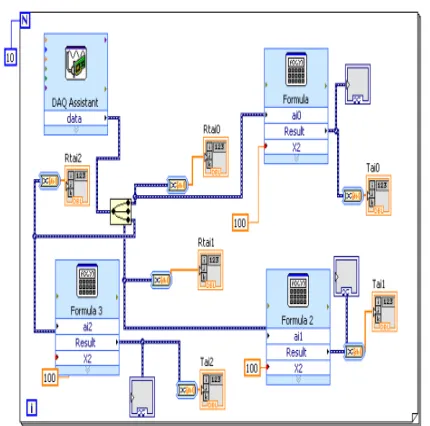
[image:5.612.97.310.173.530.2]Figure 1. Creates a window of the diagram in Lab View
Figure 2. Meteorological Parameters In Labview Format Opened With Graphics Editor National
Instruments Labview
3 EXPERIMENTAL MATERIALS AND METHODS
Currently, three types of heliostat automation systems are used, i.e.:
- the individual automatic control system; - the centralized monitoring and control system;
- the combined monitoring and control system.
The operation concept of the individual automatic control system is that each heliostat
operates individually, independently of each other, and each of them is equipped with tracking, positioning and orientation devices.
The centralized automation system monitors and controls the whole heliostat field from the operator's room.
The combined automation control system includes both of the above control systems [3, 17].
Let us consider the centralized control system for solar power station (SPS) automation. In addition to individual heliostat control system devices, the centralized control system includes centralized control devices with functions of feedback and control of each heliostat's orientation.
When controlling the SPS heliostat field, the control commands (certain codes of analog or digital signals) are sequentially transferred in a group or separately to each heliostat individually: start of operation, movement, stop, end of operation and reset. Control commands (electric signals) are transferred to heliostats via signal cables while power is transferred via power cables. The precise control of a corresponding heliostat is achieved by introduction of a specific system of signal coding and receiver addressing. Accuracy of heliostat control will be mainly determined by accuracy of automatic control system operation.
[image:5.612.98.307.347.543.2]5853
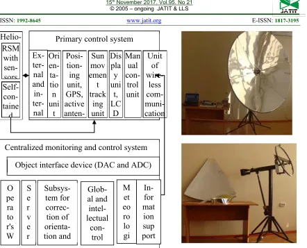
Figure 3- Centralized Monitoring And Control System
In case of use of the above automated control system (ACS) scheme with optical SPSs, each heliostat must be equipped with two electric drives with appropriate reduction gears to ensure zenithal and azimuthal turning and with four position sensors for precise pointing (on each heliostat) [1,8].
[image:6.612.91.533.49.406.2]The considered automatic heliostat control system is one of types of measuring informational and control systems, which are complexes of measuring instruments and information-processing equipment. Their characteristic feature is that they are designed to obtain information on operating parameters values, which are characterized by the “pointed” or “misaligned” states, directly from the controlled (monitored) object. That is why such control systems must be functionally linked with the controlled object and must receive information directly from the object (from heliostat groups).
Figure 3a- Experimental Device For Control System
The matter of remote information transmission, i.e. communication channels, is of special importance for automated control systems on optical SPSs with a great number of heliostats.
The automatic control unit for all heliostats of an optical SPS system deals with signals transmitting information over a distance via wires (communication channels) [11,14]. Their main ,objectives are communication effectiveness and reliability, i.e. transmission of the greatest volume of information using the most economical way with the least distortion caused by various disturbances introduced by the communication channels themselves or due to other reasons.
For sequential control of turning of separate heliostat groups, the control signals must be transmitted via the communication channel in a specific sequence. This function may be performed by a multichannel system with time distribution of the channels. When building multichannel systems, the values of controlled variables are usually represented by a uniform parameter, such as DC voltage, resistance, etc. To transmit values via a communication channel,
Helio-stat
Primary control system
Ex-
ter-nal
and
in-
ter-nal
Ori
en-
ta-tio
n
uni
t
Posi-
tion-ing
unit,
GPS,
active
anten-Sun
mov
emen
t
track
ing
unit
Dis
pla
y
uni
t,
LC
D
Man
ual
con-trol
unit
Unit
of
wire-less
com-
muni-cation
RSM
with
sen-sors
Self-
con-taine
d
Centralized monitoring and control system
Object interface device (DAC and ADC)
5854 the uniform parameter is converted to an intermediate parameter, which ensures the least errors caused by instability of communication channel parameters or disturbances. At the receiving point, the intermediate parameter is converted to direct current or other signals allowing to register the values of controlled variables or reproduce them.
4 RESULTS AND ANALYSIS
Thus, analysis of design, technical parameters of heliostats on operating tower-type SPSs, as well as analysis of the composition, functions and operation of automation systems allow us to make the following conclusions [5,9,15]:
- land area utilization efficiency is not high, as heliostats are bulky and, accordingly, the area occupied by a heliostat field is very large;
- the cost of a heliostat with the reflective surface area of 50 m2, a tower with height of 80
m or more, equipped with a tracking system, position sensors, electronic positioning and orientation devices is relatively high;
- large overall dimensions and weight of heliostats complicate their control in terms of accuracy of sun rays pointing to a receiver (free play, deformation, etc.);
- coordination of the industrial computer with controlled objects requires a great amount of DAC and ADC inputs and outputs;
- high power consumption by automation devices and the monitoring and control system.
In an optical system of tower-type SPS, the communication with the upper level of the automation system is carried out via a signal cable network. Heliostat power supply is arranged via a power cable network. Power and signal cables are laid in special ducts, trays and trenches. Currently, costs of cables and their laying are rather high, and they comprise 10% of the SPS's total cost.
With development of network and telecommunications technologies, wireless communication between detectors, transducers and industrial logical controllers is widely used in modern SCADAs. These devices are small and may be embedded directly into primary automation facilities. These devices are cheap and their application is more advantageous than laying hundreds meters of cable. That is why, to reduce costs and expenses on purchase and laying of signal cables, we propose to use cheap but effective wireless devices.
[image:7.612.325.554.221.356.2]This device can transmit both analog and discrete signals over a distance of up to two kilometers. The transmit and receive speed is 10 Mbit/s, the transmitter's operating frequency is 2.8 mHz. power supply is 5 V. The heliostat is equipped with RSM, electronic RSU motor control unit and wireless receiver and transmitter. To provide them with DC power, we propose to equip every heliostat with a self-contained power supply. [11,12,15]
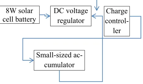
Figure 4: - Block Diagram Of Self-Contained DC Power Supply Composition
This power source (PS) consists of the following units presented in Figure 5.
This PS is cheap and small-sized. The solar panel is installed directly on the heliostat's reflecting surface. Heliostat operates only in weather when concentrated solar radiation in the receiver is sufficient for steam generation, while the rest of the time it is in the standby mode.[15] That is why use of a solar battery-powered self-contained power supply in our opinion is more advantageous than use of centralized power supply from the industrial network. It should be noted that this self-contained PS is designed to supply several adjacent small-sized heliostats.
8W solar
cell battery
DC voltage
regulator
Charge
control-ler
5855
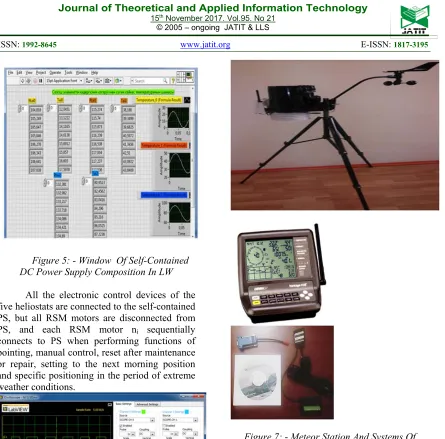
Figure 5: - Window Of Self-Contained
DC Power Supply Composition In LW
All the electronic control devices of the five heliostats are connected to the self-contained PS, but all RSM motors are disconnected from PS, and each RSM motor ni sequentially
connects to PS when performing functions of pointing, manual control, reset after maintenance or repair, setting to the next morning position and specific positioning in the period of extreme weather conditions.
Figure 6: - Calculation Of Parameters
Impulse Sensitive Elements Using Virtual Oscilloscope
Thus, the monitoring and control methods fundamentally change when using a self-contained PS.
[image:8.612.91.301.428.570.2]
Figure 7: - Meteor Station And Systems Of
Wireless
5 CONCLUSIONS
5856 will allow to adapt and combine the functions of control and surveillance into one whole, which will reduce the ratio of the inertia and lag of the tracking system through the use of a combined tracking system. Software management "constantly ahead of the curve" adjusts the coordinates of the position of the Sun and heliostat and thereby less time spent on search of the Sun in the celestial sphere. [15]
Tracking inaccuracy calculations and available conclusions given us the 15% efficien-cy factor based on the defined general relation between the defocusing angle and misalign-ment angle in measuring planes of the optical tracking sensor. [19] It was shown that for cases of both concentrator and heliostat modes of tracking, is always equal to , although the na-ture of their changing as well as their projections may vary, and that in practice the actual tracking inaccuracy in the sensor planes must not exceed
a = h 0.7. [16]
Common link between the defocusing angle and misalignment angle in measuring planes of the tracking optic sensor has been determined, we demonstrated that = always, both in the concentrator and in the heliostat tracking mode, though the nature of their variation and their projections may differ, and in practice the actual tracking inaccuracy in sensor planes must not exceed a = h 0.7.
As distinct from other measuring informational systems, the described heliostat control system operates only when tracking parameters deviate towards the maximum permitted values. Thus, the considered diagram provides a much simpler way of comparing the obtained parameters against the preset parameters.
In contrast to existing foreign analogues we have developed the automation system has a centralized tracking system, the intelligent part of the system automation performs a logical analysis of the weather condition and independently produces the mode selection optical system. Monitoring and control between the automation system and the optical system is carried out by wireless digital communication.
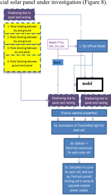
Simulation Algorithm Design The simulation is designed using MATLAB©. The model in-takes data at an hourly base for a typical meteorological year; builds up geometric structures of sky dome, ground as reflector, panels and their racking posts; checks the ray blocking and shading due to the geometry; and outputs the annual energy generated by a
[image:9.612.331.523.96.433.2]bi-facial solar panel under investigation (Figure 8).
Figure 8 The Top-Layer Scheme Of The Bifacial Solar Panel Simulation Algorithm
First of all, although this simulation intends for South Kazakhstan implementation, it can be applied to anywhere in south hemisphere. This simulation model set up a complicated scenario model with detailed consideration of various aspects.
More speeches are detailed below:
X Contrary to expectations, the posts of the casting shades of the beam significantly impact the panel annual energy yield.
X Intelligent system boosts about 13% of the annual yield from the mono-facial solar panel of the same quality when set south facing, latitude tilt and 1 meter clearance.
The simulation model may be used as a platform, more analysis may be executed in the future, and also more performance and functionalities may be built upon.
Based on the existing model, further investigation topics may include but not limited to the following:
5857 its physics and automatic working principles;
X OPU is an important factor in photon absorption thus increase output;
Electricity generation from solar energy has great potential because it relies mainly on abundant and clean source. However, there is a lot of mutable and immutable factors that can drive the PV module efficiency. Dust is one of the environmental factors, location-dependent, which fall under unchangeable factors. This can decrease the efficiency of PV panels, causing physical damage, weakening incoming solar radiation and increase in temperature, which leads to changes in electrical characteristics. In the future continues to develop intellectually clean the panels with a support swivel mechanisms.
6. ACKNOWLEDGEMENTS
We would like to express a gratitude to reviewers for valuable comments.
REFERENCES:
[1] Chu Tu Li Development of Field Scenario Ray Tracing Software for the Analysis of Bifacial Photovoltaic Solar Panel Performance// School of Electrical Engineering and Computer Science University of Ottawa, Canada, 2016
[2] U. Thein Lin stepper motor control system for moving the frame of the solar power plant. Natural and Technical Sciences. - M .: "The company Sputnik +". № 1. 2009.- pp 292-295.
[3] Sarybaev S.A.Satybaldyieva F.A Sarybay M.A. Kultas A.K .Principles of controlling the orientation of the solar solar plants №3 (30) 2014 Almaty Herald KBTU 2014 pages 80-84
[4] Sarybaev A. Research and development of an automated control system of heliostats to extend the functionality of a large solar furnace capacity of 100kV. Abstract of Cand. Ph.D. T .: 2006. 25c.
[5]. Klychev SI Simulation of optical-power characteristics of solar radiation concentrators. Solar technology, 2002, № 3 - pp 59-63
[6] Wolf R. Efficiency and Peak Capacity Gains through Solar-Thermal Feed Water Pre-Heating and Steam Generation using Compact Linear Fresnel Reflectors. Solar
Heat & Power Europe GmbH. Mulheim/Ruhr. Germany. 2008. E mail:[email protected].
[7] Beysembekova R.N.,Sarybaev A.S. Schematic diagrams of the automated control systems, geolocation, and the equations of motion of solar installations for the position of the sun. II International Scientific and Practical Conference "Information and telecommunication technologies: education, science and practice", 2015.
[8] Masafumi Yamaguchi A, Tatsuya Takamoto B, Kenji Araki C, Nicholas Ekins-Daukes. A Multi-junction III-V solar cells: current status and future potential. Solar Energy. 2005. V. 79. pp.78-85.
[9] Beysembekova R.N. Sarybaev A.N.Kocherova A.N. Software Development of an automated experimental solar control system. №5.2014 Bulletin of the Kazakh Academy of Sciences Almaty 2014 pp 188-198
[10] Zahidov RA Mirror concentration of radiant energy system. T .: "FAN". 1986 - 173s. [11] S.U. Ismailov, F.A., Satybaldiyeva, R.N.
Beysembekova, A.S. Saribaev, A.A., Musabekov, A.S. Ismailov Electronic circuit based on pic microcontroller for heliostat departments with a support rotating mechanism for tracking the sun. REPORTS OF THE NATIONAL ACADEMY OF SCIENCES OF THE REPUBLIC OF KAZAKHSTAN 2016 • 3
[12] Sarybaev A. Research and development of an automated control system of heliostats to extend the functionality of a large solar furnace capacity of 100kV. Abstract of Cand. Ph.D. T .: 2006. p 25
[13] Archer В. Comments on "Calculating the position of the sun". Solar Energy. 1980. V. 25. p. 91.
[14] Joseph J. MichalskyThe Astronomical Almanac's Algorithm For Approximate Solar Position (1950-2050) Solar Energy. 1988. V. 40. № 3. pp. 227-235.
5858 UNIVERSITY GANDHINAGAR- 382007, GUJARAT, INDIA 2016, pp. 31-40
[16] S. AlFaify, Y. S. Rammah, H. Y. Zahran, F. Yakuphanoglu, Mohd. Shkir,Optical Properties of Nano-Rods PTCDA Thin Films: an Important Material for Optoelectronic Applications Natural Sciences Publishing (NSP)OrganoOpto-Electronics (OOE) Vol. 2 Jul. 2016
[17] Yurchenko A.V., Kozlov A.V. The long-term prediction of silicon solar batteries functioning for any geographical conditions Proceedings of 22st European PV Solar Energy Conference and Exhibition. Milan 3-7 September. 2003-7. pp. 3019-3022.
[18] Aipov P.C., Yarmukhametov W.R. Improving the efficiency of solar power plants. Mechanization and electrification of SH 2007.- №9 -C. 29-30.
[19] Witzke A. Neuman J. Kaluza. Test of Device Accelerated Ageing of Polymeric Material in High Concentrated Sunlight at the DLR Solar Furnace. //5th Cologne Solar Symposium. 2001. pp. 152-158.