ORIGINAL RESEARCH ARTICLE
DESIGNING THE EFFICIENT DFIG SYSTEM BACK-TO- BACK
CONVERTER TO REPLACE LCL WITH LLCL FILTER
Sandhya Rani Ganipalli and Vidhya Fulmali
Electrical & Electronics Engineering Dept IES, IPS Academy Indore, Indore, India
ARTICLE INFO ABSTRACT
This report gives the proper understanding of conceptual power control by using direct space vector control technique and its power quality improvement conducted with DFIG. A higher order passive power filter (LLCL-filter) for the back to back converter is becoming attractive for industrial applications due to the possibility to reduce the cost of the copper and the magnetic material. It is concluded that the back to back converter compared with the LCL-filter, the proposed LLCL-filter can not only save the total filter inductance, but also reduce the damping power losses for a stiff grid application. The proposed BTB with LLCL-filter having lesser THD percentage and lesser converter losses compared with LCL-filter. Finally in this report back to back converter with both the filters are compared and all the results are simulated by MATLAB/SIMULINK software with FFT analysis.
*Corresponding author
Copyright ©2017,Sandhya Rani Ganipalli and Vidhya Fulmali. This is an open access article distributed under the Creative Commons Attribution License, which permits unrestricted use, distribution, and reproduction in any medium, provided the original work is properly cited.
INTRODUCTION
A Doubly fed induction generator (DFIG) is also called as wound rotor induction generator. Doubly-Fed means, it having both the stator and rotor of an induction machine with a wound rotor is connected to electrical sources. This is popular for the power generation applications to present generations with limited variable speed range. This DFIG can produce or consume power from both stator and rotor of the machine depending upon the speed of the shaft (VijayaRaju Vasipalli, 2015). Depending upon the value of a slip s, the operation of a DFIG can be classified in three different modes (Phipps, 1997).
< … s > 0..., Sub synchronous mode > … s < 0..., Super synchronous mode = … s = 0..., Synchronous mode
The operation and control of a Doubly-fed Induction Generator (DFIG) system. This DFIG system is currently the system of choice for multi-MW wind turbines. The aero-dynamic system must be capable of operating over a wide range of wind speeds in order to achieve an optimum aerodynamic efficiency by tracking the optimum tip-speed ratio. Therefore, the rotor of the generator must be able to operate at a variable rotational speed. Back to back converter is a two stage of converter, which converts AC-DC-AC. The AC-DC conversion is rectifier stage this converter is called as grid side converter (GSC) and the DC-AC conversion is inverter stage this converter is rotor side converter (RSC).Both converters are connected “back to back” with a DC link capacitor between them. Dc link capacitor puts voltage at constant for efficient inversion. RSC controls the torque or speed of the DFIG and also controls the power factor of the
ISSN: 2230-9926
International Journal of Development Research
Vol. 07, Issue, 08, pp.14363-14368, August,2017
Article History:
Received 19th May, 2017
Received in revised form 27th June, 2017
Accepted 10th July, 2017
Published online 30th August, 2017
Citation: Sandhya Rani Ganipalli and Vidhya Fulmali. 2017. “Designing the Efficient DFIG System Back-to- back Converter to Replace LCL with LLCL Filter”, International Journal of Development Research, 7, (08), 14363-14368.
ORIGINAL RESEARCH ARTICLE Open Access
Keywords:
Doubly fed induction generator (DFIG), Back to back (BTB) Converters;
DSVM control Schemes; Total Harmonic Distortion (THD);
Rotor-Side Converter (RSC); and Grid-Side converter (GSC);
Fig.1. DFIG System with BTB
stator terminals but the GSC only puts DC link voltage at constant GSC works at grid frequency but RSC works at different frequencies according slip speed variations. Back to back converter converts variable voltage; variable frequency into constant voltage, constant frequency or constant voltage, constant frequency into variable voltage, variable frequency in “back to back” directions (John Fletcher and Jin Yang, 2010).This three-phase AC-DC-AC converter is also included in the induction generator rotor circuit through filter topology. The power electronic converters need only be rated to handle a fraction of the total power, and the rotor power is typically about 30% nominal generator power (John Fletcher and Jin Yang, 2010). Therefore the losses in the power electronic converter can be reduced, by using different filter topologies such as LC, LCL and LLCL-filters, compared to a system where the converter has to handle the entire power and the system cost is lower due to the power electronic devices. DSVM CONTROL TECHNIQUE
Rotor Side Converter (RSC) Control
This section will detail the vector-control techniques used for the independent control of torque and rotor excitation current in the DFIG and decouple control of the active and reactive power supplied to the grid. The vector control for the generator can be embedded in an optimal power tracking controller for maximum energy capture in a wind power application. By controlling the active power of the converter it is possible to vary the rotational speed of the generator as well as the speed of the rotor of the wind turbine shaft. This can be used to track the optimum tip-speed ratio as the incident wind speed changes, thereby extracting the maximum power from the incident wind. The grid-side converter control gives potential for optimizing the grid integration with respect to steady-state operation conditions, power quality and voltage stability.
Voltage Source Inverter Control
The Inverter provides the excitation for the induction machine rotor. With this PWM converter it is possible to control the torque hence the speed of the DFIG and also the power factor at the stator terminals. The Inverter provides a varying excitation frequency depending on the wind speed conditions. The induction machine is controlled in a synchronously rotating dq-axis frame, with the d-axis oriented along the stator-flux vector position in one common implementation. This is called stator-flux orientation (SFO) vector control. In this way, a decoupled control between the electrical torque and the rotor excitation current is obtained. Consequently, the active power and reactive power are controlled independently from each other. To describe the control scheme, the general Park’s model of an induction machine is introduced.
Using the motor convention in a static stator-oriented reference frame, without saturation, the voltage vector equations are
(5.12)
(5.13) Where is the stator voltage imposed by the grid. The rotor voltage is controlled by the rotor-side converter and used to perform generator control.
The flux vector equations are
(5.14)
(5.15) Where Ls and Lr are the stator and rotor self-inductances: Ls=Lm+ Lls, Lr=Lm+ Llr
Under stator-flux orientation (SFO), in dq-axis component form, the stator flux equations are:
(5.16)
Defining leakage factor and equivalent inductance as
The rotor voltage and flux equations are (scaled to be numerically equal to the ac per-phase values):
(5.17)
(5.18) Where, the slip angular speed is ωslip = ωs - ωr.
The stator flux angle is calculated from
(5.19) Where, θs is the stator-flux vector position.
control. The reference q-axis rotor current irq*can be obtained either from an outer speed control loop or from a reference torque imposed on the machine. These two options may be termed a speed-control mode or torque-control mode for the generator, instead of regulating the active power directly. For speed-control mode, one outer PI controller is to control the speed error signal in terms of maximum power point tracking. Furthermore, another PI controller is added to produce the reference signal of the d-axis rotor current component to control the reactive power required from the generator. Assuming that all reactive power to the machine is supplied by the stator, the reference value ird
*
may set to zero. The switching dynamics of the IGBT-switches of the rotor converter are neglected and it is assumed that the rotor converter is able to follow demand values at any time.
The control system requires the measurement of the stator and rotor currents, stator voltage and the mechanical rotor position. There is no need to know the rotor-induced EMF, as is the case for the implementation with naturally commutated converters. Since the stator is connected to the grid, and the influence of the stator resistance is small, the stator magnetising current ims can be considered constant (Pena et al., 1996). Rotor excitation current control is realised by controlling rotor voltage. The ird and irq error signals are processed by associated PI controllers to give vrd and vrq, respectively, from the rotor voltage equations
(5.20) To ensure good tracking of the rotor dq-axis currents, compensation terms are added to v′rd and v′rq to obtain the reference voltages vrd* and vrq* according to
(5.21)
The electromagnetic torque is
(5.22) For the stator-voltage oriented control the above equation is an approximation. However, for stator-flux orientation, the stator flux current ims is almost fixed to the stator voltage. For torque mode control, since it is difficult to measure the torque, it is often realised in an open-loop manner. The torque can be controlled by the q-axis component of the rotor current irq. Therefore, the q-axis reference current, irq
ref
can be determined from the reference torque Teref as
Grid Side Converter (GSC) Control
GSC maintains the DC link voltage constant and also controls the power factor.
FILTER TOPOLOGY
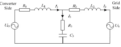
[image:3.595.330.541.190.272.2]Design of LCL Filters
Fig a. presents the schematic diagram of an LCL filter which is inserted between a PWM converter and the grid. Where, UO is terminal voltage of PWM converter, US is grid voltage, L1is the converter side inductor, R1is the equivalent resistance of L1, L2 is the grid side inductor, R2is the equivalent resistance of L2, C3is the capacitor, R3 is the damping resistor in series with C3.
Fig a. LCL filter equivalent circuit diagram (9)
Ignoring R1and R2, the LCL filter can be viewed as L2and C3paralleled, then, together they are in series with L1.
The transfer function between the input voltage UO and the output current I2is:
[image:3.595.309.557.419.534.2]
LLCL Parameter Design Procedure
Fig b. LLCL filter equivalent circuit diagram (12)
Converter-Side Inductance L1
Being placed at the converter immediate output, L1 must be sized such that its peak-to-peak current ripple at the converter switching frequency fs does not exceed α times of its peak rated current Iref. According to (Phipps, 1997) α can be up to 60% for an LLCL filter with better harmonic attenuation at the converter switching frequency. Based on the derivations presented in (Phipps, 1997), L1 can then be sized with
, where Udc is the dc-link voltage marked in Fig. b.
Capacitance Cf
Cf can be computed after deciding on L1, fs=1/(2π ) and a
value for frc ≥ fs / (4λ) (= fs / 6 if λ = 1.5) that satisfies the robust
stability criterion. Value for Cf is therefore not unique, but varies with
parameters used for computing it. Where Cf in p.u. is shown to
increase with smaller fs and bigger λ. A further constraint should
therefore be introduced, which in most cases, is to select Cf such that
In terms of its base value, Cf is then constrained according to Cf ≤
5% × Cb, which for the implemented filter.
Inductance Lf
After deciding on Cf, inductance Lf can be computed immediately since they form a series trap at the converter switching frequency of fs = 10 kHz. The extent of attenuation introduced by the series trap is however influenced by its quality factor Q expressed as.
Q= (1)
n= (2) Where Rf represents the combined equivalent series resistance of Lf and Cf. Quality factor Q therefore depends on both Rf and n defined in (eq.2).
Grid-Side Inductance L2
Inductance L2 of the LLCL-filter is the final parameter to design. Its value can be comparably small since it carries no dominant harmonics around the switching frequency, which instead, have been diverted away by the middle LfCf trap. Inductance L2 therefore needs to attenuate only harmonics around the second integer multiple of the switching frequency to be lesser than 0.3%. The overall range of system resonance frequency fr variation can then be computed using (15) by substituting the two probable extreme values of the grid inductance L2. The lowest fr computed will however still be higher than frc. By further placing them (frc and fr) above fs / 6, (15) will always be met, implying that the designed LLCL -filtered converter will always be robustly stable regardless of how L2 varies (13).
BTB with LCL-filters in DFIG System
BTB with LLCL-filters in DFIG System
Converter losses in LCL & LLCL
FFT analysis for LCL & LLCL
Output Results of BTB with filter
System Parameters LCL LLCL
Losses 600W(Average) 120W(Average)
THD (%) 33.98% 0.03%
Voltage Mag. at fundamental freq.
0.8139 (pu) 0.8985(pu)
Current Mag. at fundamental freq.
0.9967 (pu) 1.159(pu)
Base Power 9 (MW) 9 (MW)
Total output power 12.15 (MW) 14.04(MW)
Conclusion
From both the filters it can be observed that LLCL-filters were efficient one to design the back to back converter with DFIG system for variable wind speeds. In order to track maximum power, back to back converter adjusts the induction generator terminal frequency, and thus the turbine shaft speed. MATLAB simulation and analysis results show that the THD of the current after filtering of BTB with LCL is 33.98% and 0.03% with LLCL-filter respectively, which verified the
effectiveness of the designed filters in attenuating harmonics produced by the back-to-back converter. Compared LLCL with the LCL-filter, an advantage of the A higher order passive power filter (LLCL-filter) for the grid-tied converter is becoming attractive for industrial applications due to the possibility to reduce the cost of the copper and the magnetic material. It is concluded that compared with the LCL-filter, the proposed passive damped LLCL-filter can not only save the total filter inductance but also reduce the total power losses for a stiff grid application.
REFERENCES
Bloemink, J. M., Green, T C. 2011. “Reducing Passive Filter Sizes with Tuned Traps for Distribution Level Power Electronics,” in Proc. IEEE EPE, Aug. 2011, pp. 1-9. Bogalecka, E. and Krzeminski, Z. 1993. "Control systems of
doubly-fed induction machine supplied by current controlled voltage source inverter, " in Sixth International Conf. on Electrical Machines and Drives, Conf. Publ. No. 376, Sep, pp. 168 – 172.
Deng, Y., Wang, Y., Teo, K.H., Harley, R.G.” A Simplified Space Vector Modulation Scheme for Multilevel Converters” TR2015-048 March 2016, MITSUBISHI
ELECTRIC RESEARCH LABORATORIES
http://www.merl.com
John Fletcher and Jin Yang 2010. Introduction to the Doubly-Fed Induction Generator for Wind Power Applications, Paths to Sustainable Energy, Dr Artie Ng (Ed.), ISBN: 978-953-307-401-6, In Tech.
Min Huang, Student Member, IEEE, Xiongfei Wang, Member, IEEE, Poh Chiang Loh, and Frede Blaabjerg, Fellow, IEEE “LLCL-filtered Grid Converter with Improved Stability and Robustness”, IEEE Transactions on Power Electronics.DOI10.1109/TPEL.2015.2467185.
Pena, R., Clare, J.C. and Asher, G.M. 1996. "A doubly fed induction generator using back-to-back PWM converters supplying an isolated load from a variable speed wind turbine, " Electric Power Applications, IEE Proc., vol. 143, Issue: 5, Sept. pp. 380 – 387.
Peng Zhan, Student Member, IEEE, Weixing Lin, Student Member, IEEE, Jinyu Wen*, Member, IEEE, Meiqi Yao, Naihu Li .,Member, IEEE” Design of LCL Filters for the Back-to-back Converter in a Doubly Fed Induction Generator” IEEE PES ISGT ASIA 2012 1569538915. Phipps, J. K. 1997.“A transfer function approach to harmonic
filter design,” IEEE Ind. Appl. Mag., vol. 3, no. 2, pp. 68– 82, Mar./Apr.
Prof. Dr.-Ing. Ralph Kennel” Power Electronics Exercise: Space Vector Modulation” https://www.eal.ei.tum.de/ fileadmin/tueieal/.../08_Space_vector_modulation.pdf. Sangin, L., Kui-jun, L. and Dong-seok, H. 2008. "Modeling
and control of a grid connected VSI using a delta connected LCL filter," in Industrial Electronics, 2008. IECON 2008. 34th Annual Conference of IEEE, pp. 833-838.
Space vector modulation - Wikipedia https://en.wikipedia. org/wiki/ Space vector modulation.
SPACE VECTOR MODULATION FOR THREE-LEG VOLTAGE... https:// theses.lib.vt. edu/theses/available/etd-2798-1216/unrestricted/chap2.pdf
VijayaRaju Vasipalli, student, Vikalpkulshrestha, student, Prof.S.P. Phulambrikar. “Power Quality Improvement in DFIG System with MC in Wind Energy Generation with Space Vector Control Techniques” 2015 IEEE International
0 0.02 0.04 0.06 0.08 0.1 0.12 0.14 0.16 0.18 0.2
200 400 600 800 P -l os s (W a tts ) Time (seconds) Converter Pow er Losses (P-loss) With LCL
Offset=0
0 0.02 0.04 0.06 0.08 0.1 0.12 0.14 0.16 0.18 0.2
20 40 60 80 100 120 140 P -los s ( W at t s ) Time (seconds) Converter Power Losses (P-loss) w ith LLCL
Conference on technological Advancements in power and Energy.
Weimin Wu, Shuangshuang Feng, Junhao Ji, Min Huang, Frede Blaabjerg “LLCL-Filter Based Single-Phase Grid-Tied Aalborg Inverter”978-1-4799-6768-1/14/$31.00 ©2014 IEEE.
Zhou, Y., Bauer, P., Ferreira, J.A., Pierik, J. 2009. “Operation of Grid-Connected DFIG Under Unbalanced Grid Voltage Condition” IEEE Trans. Energy Conversion., vol. 24, no.1, pp.240-246.
Zinger, D.S., Muljadi, E.1997. "Annualized wind energy improvement using variable speeds," IEEE Trans. on Industry Applications, vol. 33 , Issue: 6 , pp. 1444 – 1447 Nov.-Dec.