Experimental Analyses of Automatic Single
Plate Clutch in Automatic Transmission and
Its Performance Testing
Priyanka B.Chaudhari#1, Prof. R.Y.Patil*2, Pravin S.Nikam#3, Dhiraj V.Mahajan*4 #1
M.E Scholar SGDCOE Jalgaon (MS), India,
#2
Professor & Head of Mechanical Engg. Department SGDCOE, Jalgaon, (MS), India
#3
Trainee at Hindustan Aeronautics Limited Nasik Division (MS), India
#4
Asst.Maintenanace Engineer Jain irrigation system limited Jalgaon , (MS), India
Abstract-Conventional transmission system uses single plate clutch with a manual transmission gear box. Many methods of automatic clutch control namely electro-magnetic clutch, pneumatic clutch control etc. have been tried but due inherent disadvantages and maintenance problems they have been replaced back by conventional method. The auto-disengagement single clutch employs only one set of compression springs instead of the usual two sets, with this arrangement it is possible to reduce the weights of the centrifugal member .When the clutch is disengaged and the engine is running at idling speed the hinged bob-weights rest against the lower or inward sides of holes in the flywheel. When the engine is accelerated above 700 to 800 rpm , the weights fly outwards and in doing so their lever ends compress the springs so as to engage the clutch plates. When the full engagement pressure between the clutch members has been attained any further increase in engine speed brings the bob weights against the outsides of the flywheel holes, thus limiting the pressure plate action. This arrangement keep the clutch in normally disengaged condition unlike the conventional clutch that is in engaged condition and has to be disengaged by manual Lever.
The modified system utilizes the centrifugal force developed by engine acceleration , where as the temporary dis-engagement of clutch required at the time of gear change is a solenoid actuated by switch in gear change knob. The hold time of the solenoid is only a few seconds thus prolongs solenoid life and reduces power consumption from battery.
The conventional clutches use full ace lining for the clutch meaning that the entire face of clutch is lined with friction material and conventionally the friction lining material used is asbestos base.
ANSYS is used for the calculation of stresses, demo model built up for testing performance of clutch at various speed. This clutch may reduce jerk, transmission losses and increase performance of automatic clutch.
Keywords- Transmission, Single plate automatic
clutch, Bob Weight, ANSYS
.
I.INTRODUCTION-II. TYPES OF FRICTIONAL CLUTCHES-
Disc or plate clutches, Single, plate or disc clutch, Multi plate or disc clutch, Cone clutches, Centrifugal clutches.
A. Single Plate clutch:
A much more power type of clutch is the single-plate clutch as shown in which a single flat circular plate is gripped between the inside face of the flywheel and a clamping plate which is made to grip the clutch plate by means of clamping levers actuated by strong spring. The amount of pressure put on the clamping plate can be varied by adjusting pins on which the end of the clamping levers pivot. The inside face of the flywheel and a clamping plate which is made to grip the clutch plate by means of clamping levers actuated spring.
Fig -1: Single plate clutch
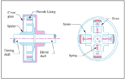
B. Centrifugal clutch:
A clutch is a machine member used to connect the driving shaft to a driven shaft, so that the driven shaft may be started or stopped at will, without stopping the driving shaft. A clutch provides an interruptible connection between two shafts. The centrifugal clutch is usually used into motor pulley. It consists of number of shoe on the inside of a rim of pulley. The outer surface of pulley is covered with friction material. These shoes which can move radialy in guides are held against the boss on the driving shaft by means of springs. The spring exert a radialy inward force which assumed to be constant. The weight shoes when revolving cause it to exert a radialy outward force (centrifugal force).The magnitude of centrifugal force depeded on speed at which shoes is revolving. A little consideration show that when centrifugal force is less than the spring force, the shoes remain same position as when driving shaft was stationary, but when centrifugal force is equal to spring force, spring is floating. When centrifugal force exceed the spring force, the shoe moves outward and comes in contact with driven member and press against it. The force with which the shoe press against the driven member is the difference of the centrifugal and spring force. The increase of speed causes the shoe to press harder and enables to be transmitted.
Fig.2 Components of Centrifugal Clutch
III. EXPERIMENTAL SETUP:
Single Plate Automatic Clutch:-The Single plate automatic clutch employs only one set of compression springs instead of the usual two sets, with this arrangement it is possible to reduce the weights of the centrifugal members.
Fig.3 Principle of Single Plate Automatic Clutch
When the clutch is disengaged and the engine is running at idling speed the hinged bob-weights rest against the lower or inward sides of holes in the flywheel. When the engine is accelerated above 700 to 800 rpm, the weights fly outwards and in doing so their lever ends compress the springs as shown in (fig.4), so as to engage the clutch plates. When the full engagement pressure between the clutch members has been attained any further increase in engine speed brings the bob weights against the outsides of the flywheel holes, thus limiting the pressure plate action.
Working of Single Plate Automatic Clutch:
There are three bob weights (A) are used in the three flywheel holes (B). These weights are carried by levers(C) which can rock on the pins mounted on the axis shown at (D). The ends of these levers engage the driving springs at the points (E). Situated between (E) & (D) is a fulcrum lever. A pin (F), carried by the pressure plate, carries a nut and washer which works over the fulcrum. Working of Single Plate Automatic Clutch:
carried by levers(C) which can rock on the pins mounted on the axis shown at (D). The ends of these levers engage the driving springs at the points (E). Situated between (E) & (D) is a fulcrum lever. A pin (F), carried by the pressure plate, carries a nut and washer which works over the fulcrum.
Fig.4 Out Side View of Single Plate Automatic Clutch
Test Rig Set Up For Single plate Automatic Clutch: In order to demonstrate the functionality of the clutch the test rig set up has developed where in the input shaft or driver shaft of clutch is driven by a variable speed motor of AC type, speed control achieved by means of an continuously variable rheostat.
The output shaft shall carry a dyno brake pulley if the brake dynamometer testing is to be carried out in order analyze the torque transmitting capacity of clutch.
Fig.5 Test Rig Set Up
IV. ANALYTICAL APPROACH:
In this section, Design and analytical process has been discussed,
Input Data, a) Motor Details,
Single phase AC motor Commutator motor TEFC construction Power = 1/15hp=50 watt Speed= 0-9500 rpm (variable) Design of Input Shaft:
MATERIAL SELECTION : -Ref :- PSG (1.10 & 1.12) + (1.17)
fs max = uts/fos = 800/2 = 400 N/mm2
This is the allowable value of shear stress that can be induced in the shaft material for safe operation.
Check for torsional shear failure of shaft Te = fs d3
16
fs act =16 x 0.252 x 103
x 123 fb act = 0.742 N/mm2
As; fs act < fs all
Worm shaft is safe under torsional load.
V.RESULT
A. AFTER LOADING CONDITION:
Fig.6 Result after loading condition
B.OUTPUT SHAFT:
Fig.7 Meshing of Output shaft
Fig.8 Stress Distribution of output shaft
VI.EXPERIMENTATION :
After conducting experiments, several trials have been taken at various speed or RPM of clutch and readings are noted also graph compared with graph of standard single plate clutch.
Fig.9 Torque comparison with manual clutch.
Fig.10 Power comparison with manual clutch.
VII.CONCLUSION
The single plate automatic clutch is having smooth engagement 95% during power transmission because of using single plate for power and torque transmission so that jerk during transmission is eliminated. It is having higher torque/ power transmission capacity and it can be analysed by testing performance of clutch. due to no jerk (only 5%) there is less vibration and less wear during torque transmission and these clutch has higher life as compare to centrifugal / Single plate clutch.
The conventional liners used in single plate clutch are asbestos base with coefficient of friction close to 0.4 resulting in lower ruction force and lower power transmission ability. Hence it is decided to replace the fricition material as FTL094 as moulded lining with non-asbestos base to confirm to the present environmental norms.
Test rig is compact in size and easier to calculate Power Vs Speed, Torque Vs speed, Brake Power Vs Speed readings. We can conclude performance of clutch by comparing reading with standards_reading.
REFERENCES
[1] Rajesh Purohit, Pooja Khitoliya, “Design and Finite Element Analysis of an automotive clutch Assemby”, 3rd
International Conference on Materials Processing and Characterisation [ICMPC 2014].
[2] Ganesh Raut, “Analysis of Multidisc Clutch Using FEA”, International Journal of Engineering Trends and
[3] Nitinchandra R. Patel, “Design of Centrifugal Clutch By Alternative Approaches Used In Different Applications”, International Journal of Innovative Research in Science, April-2013.
[4] Abhijit Devaraj, “Design optimisation of a kevlar 29 single disk friction clutch plate based on static analysis using ansys.”, International Journal of Sciences and research Technology, August, 2015
transmission and its performance testing.” International Engineering Research Journal, octomber, 2015
Report and Manual
[6] Modern Transmission Systems, Arthur W Judge [7] Engg. Mechanism, Erdman and Sandor [8] Machine Design, R S Khurmi [9] P S G Design data Book.