22 & 23.04.2017
In association with
I
nternational
Journal of
Scientific
Research in
Science and
Technology
Design and implementation of control techniques for Zeta
converter
Jajini. M
*1, Vairaprakash P
2*1PG Student, Department of Electrical and Electronics Engineering, Thiagarajar college of Engineering, Madurai, Tamil Nadu, India 2 Assistant Professor, Department of Electrical and Electronics Engineering, Thiagarajar college of Engineering, Madurai, Tamil Nadu,India
Abstract
The model proposed is Zeta voltage converter controller design and its control. The mathematical model of the zeta converter circuit operating in the continuous conduction mode is presented. PI controller, Fuzzy Logic controller and Sliding mode controller are the designed controllers. Analysis and comparison of simulation responses of open loop, close loop fuzzy logic controller and sliding mode controller are made with respect to periodic change in load. The results show that there is a significant performance and improvement in the proposed model.
Keywords : Zeta Converter; Voltage Regulation; State Space Model; Sliding Mode Control, Abbreviations and Acronyms : CCM-Continuous Conduction Mode;VRM-Voltage Regulator Module;SMC-Sliding Mode
Controller;FLC-Fuzzy Logic Controller; D-Duty cycle; e-output error variable
I.
Introduction
As the demand for high-performance, cost-effective systems continues to increase, power system design has become more challenging and complicated than ever before. The trend is DC-DC Converters with high efficiency and power saving capability.
India With the demand for portable electronics growing in India, the role played by DC/DC converters in reducing power consumption in hand-held devices is assuming greater importance. With more devices being designed so as to incorporate more features into them, portable system designers are looking at smaller and efficient DC/DC converters which perform efficiently whileincreasing battery life and system run-times. Improved efficiency, smaller form-factor, higher frequency switching and higher power densities are some of the trends that NXP is observing for DC-DC converters.
There are three main DC/DC converter technologies used with renowned applications. The first of these converters is the buck converter. Buck converters are step-down converters that output a voltage lower than the voltage that is input to the converter. The standard buck converter has an output that is equivalent to the input voltage multiplied by the duty cycle
in out
D
V
V
….. (1)Buck converters work for low voltage applications. The second commonly used converter is a boost converter. Boost converters are step-up converters that output a voltage higher than the voltage that is input to the converter. The standard boost converter has an output that is equivalent to the input voltage divided by the duty cycle.
) 1
( D
V Vout in
.….(2)
However, in many applications, a high boost ratio is required for the DC/DC converter to feed high voltage load or power grid. This cannot be satisfied by basic boost converters. Some limitation in conventional buck boost converter like inverted output, pulsating input current, high voltage stress make it unreliable for wide range of operation. So to get rid of this, ZETA converter is used.
be more with high modulation index. It also helps in reducing harmonics. Switch used is MOSFET, because it has higher speed of operation.
The controller action is provided by three different controllers. The PI controller acts as a comparative device that compares the input set predetermined value. If error is present, controller uses certain variables to correct them. The PI controller has negligible steady state error.
The controllers are fuzzy logic controller and sliding mode controller. Each control technique for the zeta converter is implemented using matlab simulation. The objective of the work is to stabilize and regulate the output voltage of converter under varying load conditions.
II.
Zeta Converter
DC-DC conversion is the stem of Power
Electronics.Many new converter topologies are still created every year. The Zeta converter is one among the new converter topology that provides a regulated output voltage from an input voltage varying above and below the output voltage.
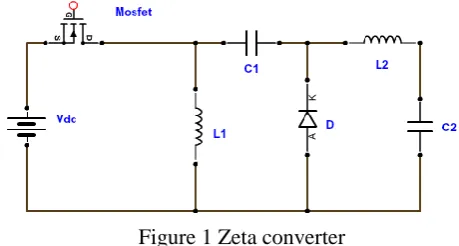
Zeta converter is a fourth order DC-DC converter. The zeta converter shown in Figure 1 is capable of converting input voltage into a non inverted output voltage, having either a lower or higher value than input voltage. The inductor and the capacitors may also have large effects on the converter efficiency and ripple voltage. The energy transfer is controlled by high frequency switching device S (MOSFET).
Figure 1 Zeta converter
A. Operating modes of zeta converter
Zeta converter is capable of operating in both continuous and discontinuous modes.The zeta converter consists of components like switch (S), inductors (L1 and L2), a diode, capacitors (C1 and C2), and a load (R).
MODE 1:
This mode is obtained, when the diode (D) is off and switch(S) is on. As shown in Figure 2 the current through the inductor L1 and L2 are drawn from the source Voltage Vs. The Inductor current iL1 and iL2
increase linearly. This mode of operation is called as charging mode.
Figure 2 Zeta Converter in ON State
MODE 2:
This mode shown in Figure 3 is attained, when the diode (D) is in ON state and switch (S) is in off state. The energy stored in the inductors discharge and is transferred to the load. The current in the inductors decreases linearly. This mode of operation is called as charging mode.
Figure 3 Zeta Converter in OFF State
Advantages of zeta converter:
Unlike a classical buck–boost converter, the zeta converter has a continuous output current. The output side inductor makes the current continuous and ripple free.
Although consisting of same number of components
negative voltage sensing, and hence reduces the complexity and probability of slowdown in system response.
B. Design equations of zeta converter
DUTY CYCLE
D= …..(3)
INDUCTANCE
L1 = …..(4)
L2 = …..(5)
CAPACITANCE
C1 = …..(6)
C2 = …..(7)
III.
Sliding Mode Controller Design
A. State space model of zeta converter
State-space averaging (SSA) is a reknownmethod formodeling switching converter.A state variable description of a system is written as follow
…… (5.1) & (5.2)
Where A is n x n matrix, B is n x m matrix, C is m x n matrix and D is reserved to represent duty cycle ratio.
For a system that has a two switch topologies, the state equations can be describe as
When switch is closed
….. (8) &(9) When switch is open
…..(10)&(11) For switch closed at time DT and open for (1-D)T,the
weighted average of the equations are
…..(12)to(18)
State space equation for on state is expressed as
…..(19)
State space equation for off state is expressed as
…..(20)
The system state space equivalent equation is
As= [0 0 (D1)/L1 0;0 0 D/L2 1/L2;(1 D)/C1 -D/C1 0 0;0 1/C2 0 -1/(R*C2)];
Bs= [D/L1; D/L2; 0; 0]; Cs= [0 0 0 1];
Ds= [0]; Vs= 12;
[Num, den]= ss2tf(As,Bs,Cs,Ds) sys= tf(num,den)
step (sys*Vs) grid
B. Determination of control parameters for SMC
The values of k is obtained by following equation
B A ……(24)
Figure 4 sliding mode control
IV.
Simulated performance of proposed
system
The dynamic performance of zeta converter is analysed using following control techniques:
1. Without feedback controller 2. With PI controller
3. With fuzzy controller 4. With SMC controller
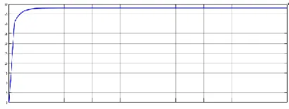
A. Zeta without feedback controller:
In open loop control of dc-dc zeta converter 20V input is fed to which is to be boosted upto 48V as per requirement and it is not obtained in open loop control. A pulse generator is used to apply the gate pulse to the power MOSFET. For open loop duty cycle chosen is 0.70
The desired output voltage 48V is not obtained in open loop circuit. The obtained output voltage is 45.94V.
Figure 5. Open Loop Response
TableI. performance analysis of converter for change in load
B. Zeta with PI controller:
The proportional gain and integral gain values of PI controller are obtained from Ziegler Nichols tuning method. The proportional gain as 0.018 and integral gain as 0.015 is taken to regulate the output voltage of proposed converter.
In PI controller, the actual value of voltage and thereference voltage are compared and the error value is given to the PI controller. The output of PI controller is then given to the relational operator where it is compared with the repeating sequence. Here ramp signal is considered.
Table II. performance analysis of closed loop PI controller
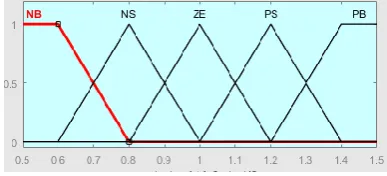
C. Zeta with fuzzy logic controller:
The fuzzy logic controller is used to regulate the output voltage of proposed converter. The error signal and change in error signal are the inputs to the fuzzy logic controller.
Figure 7. Input membership function ( error signal)
Figure 8. Input membership function ( change in error signal)
Figure 9. Output membership function
Figure 10. output voltage of Fuzzy Logic Controller
% of load Output voltage
Output power
100 48.04
95.24
75 48.21
73.56
50 48.23
33.52
25 48.45
23.725
Table III. Performance analysis of closed loop flc controller
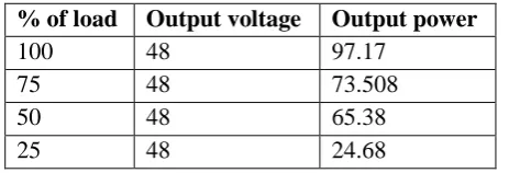
D. Zeta with SMC controller:
Here the current through inductors and voltage across capacitor are considered as the sliding surface. The gain values are calculated until the transient response is satisfactory.The measured capacitor voltages and inductor currents are made to compare with the reference values and the gain calculated are k1=k2=0.0599 , k3=0.0358 and k4=2.9423
% of load Output voltage Output power
100 48 97.17
75 48 73.508
50 48 65.38
25 48 24.68
Table IV. Performance analysis of closed loop smc controller
V.
CONCLUSION
Zeta converter has been designed. Modeling and control of a Zeta converter operating in Continuous Conduction Mode (CCM) has been presented.The output voltage response as an open-loop system has been analyzed. The Zeta converter was simulated with variation in load. The simulation was done for DC-DC Zeta converter with the various controllers such as PI controller, Fuzzy logic controller and sliding mode controller to regulate the output voltage of the zeta converter circuit. The initiative is taken to develop sliding mode control technique for zeta converter.The computation time for the proposed system gains were very short. Hence the system gives better output and is efficient. The future scope of this work is usage of solar source employing effective MPPT algorithm
VI.
Acknowledgment
The authors acknowledge the support provided by the Management, Principal and Faculty of Electrical and Electronics Engineering department of Thiagarajar college of Engineering, Madurai.
VII.
References
[1].RajanKumar, Member, IEEE and Bhinsingh, fellow, IEEE “bldc motor-driven solar pv array fed water pumping system employing zeta converter” IEEE transactions
VOL.52,NO.3,MAY/JUNE2016,PP.2315-2322.
[2].Venkatanarayanan Subramanian †and
SaravananManimaran, “ Implementation of a sliding mode controller for single ended primary inductor converter”, Journal of Power Electronics, Vol. 15, No. 1, pp. 39-53, January 2015.
[3].SubhashChander, ,Pramod Agarwal and Indra Gupta, “ Auto tuned discrete PID controller for
DC-DC converter for fast transient response” 978-1-4244-7882-8/11/$26.00 ©2011/ IEEE.
[4].J.falin, “Designing DC/DC converters based on zeta topology” Analog Applications Journal, Texas Instrumentsincorporated,pp.16-20,2010.
[5].Ali H. Ahmad, Nashwan Saleh Sultan“ Design and Implementation of Controlled Zeta Converter PowerSupply”American Journal of Electrical and Electronic Engineering, 2014, Vol. 2, No. 3, 121-128