302
Performance Evaluation Of Macro & Micro
Mobility In HMIP Networks
Osama Ali Abdelgadir , Amin Babiker A.Nabi Mustafa , Ashraf Gasim Elsid Abdallah
Abstract: Changing the location of mobile node during transmission or receiving of data always caused changing of the address of the mobile node which results in packet loss as well as delay in time taken to locate the new address of the Mobile Node , therefore delay of data receiving is caused, this problem was known as micro-mobility issue. To resolve this problem, and ascurrently, mobile IP is the most promising solution for mobility management in the Internet. Several IP micro mobility approaches have been proposed to enhance the performance of mobile IP which supports quality of service, minimum packet loss, limited handoff delay and scalability and power conservation but they are not scalable for macro mobility. A practical solution would therefore require integration of mobile IP and micro mobility protocols where mobile IP handles macro mobility and HMIP, cellular IP, HAWAII handles micro mobility. In this paper an integrated mobility management protocol for IP based wireless networks is proposed and analyzed.HIERARCHICAL MICRO MOBILITY PROTOCOL is used. To identify the impact of micro-mobility in IP based Wireless Network, to implement selected micro-mobility model of Hierarchal Micro Mobility Protocol in network simulator, and for more analysis and measurements results and for the purpose of performance comparison between both Macro and Micro mobility Protocol Management.. Simulation results presented in this paper are based on ns 2
Index Terms: HMIP, HA, CN, MN, MAP, AR,NS2 simulator
————————————————————
1 I
NTRODUCTIONHMIP stands for Hierarchal Micro Mobility IP, Itis a new technology used in this case to manage and handle IP addresses while Mobile Node(MN) changing location. Three main proposals have been suggested after IP4 and Ipv6 to eliminate this new problem of micro mobility; however all of them are cleared to be extortions of MIP not replacement to the basic system. HAWAII, Hierarchical AND CELLULAR IP are the new supporting protocols of the network system that offers better performance whenever micro mobility appears specially for real time applications such as VoIP Voice over Internet Protocol that is high effected by stability of the system. In this study a simulation of a micro-mobility and macro-mobility models using hierarchical mobile internet protocol was done.“HMIPv6” in a network simulator to test, study and analyze the performance and parameters of the system and the enhancement over MIPv6.
2
M
ICROM
OBILITYI
SSUEThe micro mobility expression stands for the changing of the location of the mobile node in a network. This kind of movement happened some times during the transmission and receiving of data which leads to the change in the node address and that is described as a handoff.
For IPv4 protocol, the recent verified address is contained within the home agent and this is the same case in mobile
Ipv6 which causes many problems. As a result of the late informing of the home agent with the new location of the node after or during the handoff the network suffers from the loss of information while sending or receiving (packet loss), this is considered as the main issue of Ipv6 and Ipv4.This has negative effect specially in the case of applications that are time sensitive such as audios and videos because of the time taken while transmitting or receiving to know the new address and this causes the loss of all the data and the need to start all over the changing the address. The time delay is also an issue faced by micro mobility.
3 H
MIPA
RCHITECTUREThis hierarchical Mobile IPv6 scheme introduces a new function, the (MAP)Mobility Anchor Point, and minor extensions to the mobile node operation. The correspondent node and home agent operations will not be affected. Just like Mobile IPv6, this solution is independent of the underlying access technology, allowing mobility within or between different types of access networks. A mobile node entering a MAP domain will receive Router Advertisements containing information about one or more local MAPs. The MN can bind its current location (on-link CoA) with an address on the MAP's subnet (RCoA). Acting as a local HA, the MAP will receive all packets on behalf of the mobile node it is serving and will encapsulate and forward them directly to the mobile node's current address. If the mobile node changes its current address within a local MAP domain (LCoA), it only needs to register the new address with the MAP. Hence, only the Regional CoA (RCoA) needs to be registered with correspondent nodes and the HA.
_______________________
Osama Ali Abdelgadir is currently pursuing masters degree program in Communications and Data Networks in Elneeelain University, Sudan, PH-+249912994072 E-mail: [email protected]
Amin Babiker A.Nabi Mustafa ,department of
computer engineering in Alneelain University ,Sudan, E-mail:[email protected]
School of Electronics, College of Engineering, Sudan University of Science and Technology, Khartoum, Sudan
(E-mail:[email protected] ;
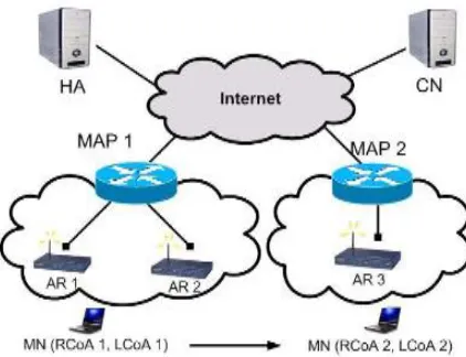
303 Fig. 1.1. The Hierarchical Mobile IPv6 protocol
(Micro–mobility & macro-mobility)Conceptual paradigm
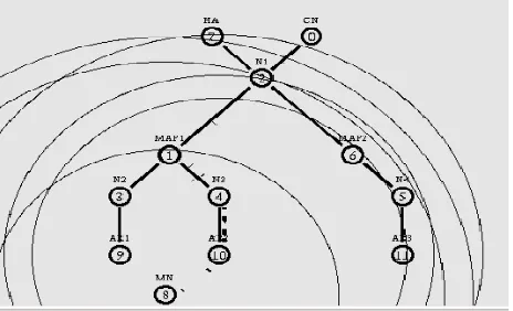
Fig. 1.2. Mobility Management in HMIPv6 Network
4 HMIPV
6
4.1 HMIPv6 Terminologies
The list of terminologies used in HMIPV6 can be listed as follow
Access Router (AR)
The AR is the mobile node's default router. The AR aggregates the outbound traffic of mobile nodes.
Mobility Anchor Point (MAP)
A Mobility Anchor Point is a router located in a network visited by the mobile node. The MAP is used by the MN as a local HA. One or more MAPs can exist within a visited network.
Regional Care-of Address (RCoA)
An RCoA is an address allocated by the MAP to the mobile node.HMIPv6-aware Mobile Node an HMIPv6-aware mobile node is a mobile node that can receive and process the MAP option received from its default router. AnHMIPv6-aware mobile node must also be able to send local binding updates (binding update with the M flag set).
On-Link Care-of Address
The LCoA is the on-link CoA configured on a mobile node's interface based on the prefix advertised by its default router. this is simply referred to as the care-of address. However, in this memo LCoA is used to distinguish it from the RCoA. Local Binding Update
The MN sends a local binding update to the MAP in order to establish a binding between the RCoA and LCoA.
4.2 HMIPv6 Operation
The network architecture shown in Figure 11.2 illustrates an example of the use of the MAP in a visited network. In Figure 11.2 , the MAP can help in providing seamless mobility for the mobile node as it moves from Access Router 1 (AR1) to Access Router 2 (AR2), while communicating with the correspondent node. HMIPv6 improves the handover management of basic Mobile IPv6 by introducing the new protocol agent MAP. MAP splits the management of the handover process into macro-mobility and micro-mobility and deals with them separately. HMIPv6 improvement over Mobile Ipv6 is noticeable especially in the micro-mobility where the coverage area is small and the handover is frequent. HMIPv6 reduces the signaling over radio interface and supports more efficient handover. Macro-mobility handover happens when
MN movesglobally from one MAP to another MAP that is located far away from each other while micro-mobility handoverhappens when MN moves locally between access router within one MAP domain. In HMIPv6, MN is assigned two addresses, regional care of address (RcoA) and on-link care of address (LcoA). These two addresses are very useful for managing. Macro-mobility and micro-mobility.
5.1Micro Mobility Problem
The micro mobility expression stands for the changing of the location of the mobile node in a network. This kind of movement happened some times during the transmission and receiving of data which leads to the change in the node address and that is described as a handoff. The characteristics considered in evaluating the methods use to solve IP micro mobility issues:
The delay at each and the time taken to send the IP packets to recent location (Signaling delay)
Lost packets through handoff.
The required signaling traffic between visited and home networks
Whether a support is needed between the foreign agent and the mobile node from routers or communication media, and does it required any particular support of the visited network. So the main objective is to improve mobility management of Ipv6, ensure full transmission of data and minimize the delay
5.2 IPMicro-Mobility
304
of service can be experienced in data exchange between mobile devices owing to packet loss or delay delivery. This delay can occur owing to round trip registration mechanism used by Mobile IP, as registration request is frequently dispatched to Home Agent and response is returned back to the Foreign Agent. Although route optimization can override such performance degradation factors to some extent, they cannot eliminate them completely.
Examples of some well known IP micro-mobility is HAWAII (Handoff-aware wireless access Internet infrastructure), Cellular IP and HMIP (Hierarchical Mobile IP). When a mobile node becomes highly mobile, the signaling overhead due to the registration becomes excessive in Mobile IP. In order to reduce this signaling overhead and provide smooth handoff, many micro-mobility protocols have been proposed. But they still suffer from problems such as scalability inefficiency in packet exchanges addresses assigned in the case of micro-mobility
Fig. 2.1. describes the movement of MN and the
6
HMIPV
6
MOBILITY6.1 Hierarchical Mobile IPVersion 6 ( HMIPV6 )M
acro-Mobility Management
Macro-mobility handover happens when MN moves globally from one MAP to another MAP that is located far away from each other while micro-mobility handover happens when MN moves locally between access router within one MAP domain. In HMIPv6, MN is assigned two addresses, regional care of address (RCoA) and on-link care of address (LcoA). These two addresses are very useful for managing macro-mobility and micro-mobility. The HMIPv6 macro-mobility management is explained by modeling the routing scheme for every message exchange between MN and its correspondent agent (CN). The over-all delay is dependent of the time required for each step in the registration operation which in-turn depends mainly on the transmission time between the nodes. The message exchange for this operation is shown in Fig.11.4. assumed the scenario that the MN is currently receiving packets from CN and starts to move to a new MAP domain. After the MN receives router advertisements, it acquires two new addresses, the RcoA2 and LcoA2.
6.2 Hierarchical Mobile IP Version 6 micro-mobility management (HMIPV6 )
The aim of introducing the hierarchical mobility management
model in MIPv6 is to enhance the network performance while minimizing the impact on MIPv6 or other IPv6 protocols. This is achieved by using the MIPv6 protocol combined with layer 2 features to manage both IP micro and macro mobility, leading to rationalization and less complex implementations in the MN and other network nodes. This hierarchicalMIPv6 scheme introduces a new function, the Mobility Anchor Point (MAP), and minor extensions to the MN and the Home Agent operations.The CN operation will not be affected. The introduction of the MAP concept minimizes the latency due tohandoffs between access routers. Furthermore, the addition of bicasting to a MAP allows for Fast Handoffs which will minimize the packet losses due to handoffs and consequently improve the throughput of best effort services and performance of real time data services. over the radio interface. Just like MIPv6, this solution is independent of the underlying access technology, allowing Fast Handoffs between different types of access networks. Furthermore, a smooth architectural migration can be achieved from Hierarchical MIPv4 networks, since a dual operation of IPv4 and IPv6 Hierarchies will be possible making use of the similarity in architecture. The introduction of the MAP concept will further diminish signaling generated by MIPv6 over the radio interface. This is due to the fact that a MN only needs to perform one regional update (MAP) when changing its layer 3 access point within the MAP domain. The advantage can be easily seen when compared to other scenarios (no MAP) where at least two BUs (Binding Updates) will be sent (to one CNand HA). A MAP may also be used as a point of access control and key distribution for the AAA protocol in IPv6.
7
MOBILITY MANAGEMENT7.1 Micro-mobility management
In this case, MN moves locally between AR within the same MAP domain. MN only changes its LCoA but itsRCoA remains unchanged and it does not have to send BUto CN/HA to inform it about its new address (see Fig3.4). The registration process is performed as follows:
1. MN sends BU to MAP through AR. 2. AR sends BU to MAP,
3. MAP performs duplicate address detection (DAD) Check.
4. DAD finished, MAP sends B_ack to MN through AR. If there is any packet addressed to MN’s RCoA, MAP will encapsulate and tunnel the packets and sends to MN through the new AR based on MN’s new LCoA.
305 . Fig. 3 Micro-mobility handover routing scheme
7.1 Macro-mobility management
The HMIPv6 macro-mobility management is explained by modeling the routing scheme for every messageexchange between MN and its correspondent agent (CN). The over-all delay is dependent of the time required for each step in the registration operation which in-turn depends mainly on the transmission time between the nodes. The message exchange for this operation is shown in Fig.4.4.We assumes the scenario that the MN is currently receiving packets from CN and starts to move to a new MAP domain. After the MN receives router advertisements, it acquires two new addresses, the RCoA and LCoA.
The description for each message exchange is as follows: 5. Mobile node sends binding update (BU) to mobility
anchor point (MAP) through access router (AR). MN needs to configure two care of addresses: An RCoA and LCoA,
6. AR receives BU and sends to MAP,
7. MAP receives the BU and will perform duplicate address detection (DAD) check. During this time MN must wait for the check,
8. MAP sends binding acknowledgement (B_ack) to MN through AR. B_ack is used to indicate that it has successfully received MN’s BU and the address is not duplicated,
9. AR sends Back and MN received it,
10. Subsequently MN sends BU to CN through AR and MAP. This BU is used to inform the CN or HA to change their destination address for the packets belongs to MN,
1.
AR receives BU and send to MAP,2.
MAP receives and send BU to CN,3.
CN receives the BU and changes the destination address from the old RCoA to new RCoA CN sends the packets to MN through MAP based on MN’s new RCoA,4.
MAP receives packets addressed to the MN’s RCoA. Packets will be encapsulated and tunneled from the MAP to MN through AR based on MN’s LCoA.5.
AR sends packet to MN.After the MN receives packets from CN, it de-capsulate the packets and then process them in the normal manner (this means the registration operation is done).
8
S
IMULATION8.1 Methodology
The method used in this project is network simulator(NS-2) that willrun the code of the HMIP scenario to test packets of TCP (Transmission Control Protocol ) The certain parameters in this project will be used in order to evaluate the performance of the network are packet delay, packet drop and throughput. NS-2 simulator uses an extension of HMIPv6 which was designed to support the functionality of all MIP protocols.
Fig. 4.1. Network Topology in the network Simulator
8.2 The Simulation Assumptions
For the simulation model of HMIPv6the chosen parameters are the maximum packet =512 bytes and one mobile node with the coordinate of topology at x = y = 1000, and time of simulation at 80 s but starting of the transmission is at t = 10, with 3 wired nodes(Access routers ) , and two special routers called mobility anchor point (MAP and MAP2) ,with a home agent and correspondent node , and a mobile node moves between the three access routers .The simulation network has TCP traffic from CN to MN .those parameters was used to calculate the following in order to evaluate the system performance :
Packet delivery ratio = packet delivered X 100 /packet pent Packet dropped = packet sent – packet received
End to end delay = sum of delay samples / number of samples’
Fig. 4.2. Handover in the case of Micro - Mobility
8.3 Simulation Scenario
306
environment. 802.11 WLAN is used as the wireless medium. The patch for HMIPv6 was design and implemented, The simulation is tested for TCP session , And A hierarchical address is used for all the nodes . To add new routing protocol in NS-2, some necessary changes in NS files was done . All wired nodes connecting with duplex links, whose characteristics shown in Fig5.4, over each link. These features are bandwidth in Mbps and the delay in ms. Table 1 shows configuration of nodes.
8.4 Results and Analysis
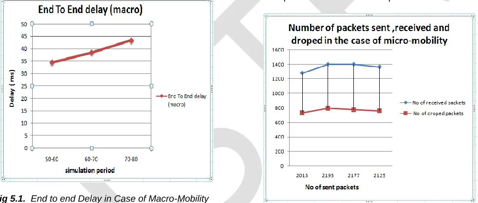
Table 1and table 2 represents the end to end delay of packets transfer during the simulation .and Fig. 5.1 and Fig. 5.2 shows them in term of graphs as packet transfer delay vs. time for HMIPv6 for both micro-mobility case and macro mobility respectively and for TCP traffic. The figure explains the graphical representation output of the simulation. The Y-axis shows the packets transferred while the X-axis represents the Time in seconds.
Fig 5.1. End to end Delay in Case of Macro-Mobility
TABLE 1: End to end delay in Case of Macro Mobility
Over Head (TCP) time in macro-mobility
Average end to End delay(ms)
50-60 34.5673
60-70 38.5787
70-80 43.4224
Fig 5.2. End to End Delay in Case of Micro-Mobility
TABLE 2: End to end delay in Case of Macro Mobility
Over Head (TCP) time in micro-mobility
Average end to End delay(ms)
0-20 15.6773
20-30 20.6919
30-40 25.6794
40-50 30.5621
8.5 T
HEC
OMPARISONP
ARAMETERS8.5.1 Dropped Packets
Table 4& figure 8.5 describe the relation between the packets sent, received and dropped in the case of micro-mobility. Table 5 & figure 9.5 represents the relation between the packets sent ,received and dropped in the case of macro-mobility.It is clear to see that the number of dropped packets is very small when compared with the number of packets received
Fig8.5.packets sent, received and dropped in micro-mobility case
TABLE 4 packets sent, received and dropped in the case of micro-mobility
Packets sent Packets received
Packets Drop
2013 1280
733
2195 1400
795
2177 1400
777
2125 1365
760
307
Fig 9.5. Packets sent, received and dropped in macro-mobility
Case
TABLE 5: Packet sent, received ,and dropped in macro – Mobility
Packets sent Packets
received Packets drop
1625 1093 532
1463 1005 541
1768 1159 692
8.5.2: Packet Delivery Ratio
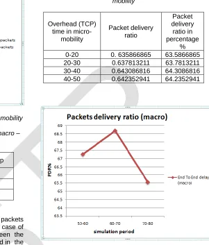
Table 6& figure 10.5 describes the ratio between the packets sent and received during the simulation period in the case of micro-mobility. Table 7& figure 11.5 the ratio between the packets send and received during the simulation period in the .case of macro-mobility. From the figure it's clearly that the delivery ratio of the packets are not so far from each other and this is a good result. Here there is a differences in the ratio of delivered packets it is small when the handover from (MAP1) to (MAP2) occur and the in the period between (60-70) it reach the highest value then after the simulation near to end the packets delivery ratio go down to have a minimum value . of course the results on the first case is better than on the other according to the delay that happen during the movement of the mobile node
Fig10.5. packets delivery ratio in micro-mobility case
TABLE 6: packets delivery ratio in the case of micro-mobility
Overhead (TCP) time in
micro-mobility
Packet delivery ratio
Packet delivery
ratio in percentage
%
0-20 0. 635866865 63.5866865
20-30 0.637813211 63.7813211
30-40 0.643086816 64.3086816
40-50 0.642352941 64.2352941
Fig11.5. packets delivery ratio in macro-mobility
TABLE. 7: Packets delivery ratio in the case of macro-mobility
Overhead (TCP) time in
macro-mobility
Packet delivery ratio
Packet delivery ratio in percentage %
50-60 0. 672615384 67.2615384
60-70 0.686944634 68.6944634
70-80 0.655542986 65.5542986
4
C
ONCLUSSIONNetwork mobility support involves taking care of handover delays. Many schemes for handling the delay due to handover have been proposed. In order to improve performance in the face of high rate of mobility, the existing schemes, FMIPv6 tend to increase the overload on MAP. Taking this in consideration, the present work improves handover logic using hierarchical mobile IPv6.After analyzing the results of this study, we can conclude that our newly proposed scheme reduces the packet loss, the handover delay and the MAP is free from overload
10
F
UTUREW
ORK308
work will be focused more in the random movement (ping pong movement) for the mobile node. That will give a more accurate evaluation for the seamless mobile IP approach especially for the movement tracking scheme.
2. To increase the packet delivery ratio and to reduce the delay .we suggest to do Integration of FMIPv6 in HMIPv6 to improve hand-over performance which will give new protocol called FHMIPv6 (Fast handover mobile ip version 6).
R
EFERENCES[1] D. M. Akbar Hussain. (2009). Wireless networks, information processing and systems: International Multi Topic Conference
[2] Jyh-Cheng Chen, Tao Zhang. (2004). IP-based next-generation wireless networks: systems, architectures, and protocols. John Wiley and Sons.
[3] Ramjee, R., La Porta, T., Thuel, S., Varadhan, K., and Wang, S., HAWAII: a domain based approach for supporting mobility in wide-area wireless networks, Proceeding of International Conference on Network Protocols.
[4] R. Ramjee, T. La Porta, S. Thuel, K. Varadhan, L. Salgarelli. (2000). IP micro-mobility support using HAWAII.
[5] Retrieved:http://www.cse.tkk.fi/fi/opinnot/T110.5190/200 0/Micro-mobilitysolutions/micro-mobility.html
[6] Retrieved from:
http://comet.columbia.edu/cellularip/overview.htm
[7] Lisa Lindqvist, (2000), Micro-mobility for IP. Helsinki University of Technology,
[8] Han-Chieh Chao. (2001) "An overview and analysis of mobile Internet protocols in cellular environments", Vol. 11(5), pp.435 – 450
[9] Myung-Kyu Yi, Chong-Sun Hwang.A New IP Paging Protocol for Hierarchical Mobile IPv6 .