Internal Fixation of Femoral Bone Comminuted Fracture - FE Analysis
V. Rankovic1, B. Ristic2 , M. Kojic1, 3
1 Center for Scientific Research of Serbian Academy of Sciences and Arts and University of
Kragujevac
Jovana Cvijica bb, Kragujevac, Serbia e-mail: [email protected],
2 Clinical Center of Kragujevac, Faculty of Medicine,
The University of Kragujevac, Svetozara Markovica 69, Kragujevac, Serbia
3 Harvard School of Public Health, 665 Huntington Ave., Boston, MA 02115, USA
Abstract
This paper presents finite element analysis of the mechanical stability of some fixation solution often used in treatment of the femoral bone comminuted fractures. In this study we consider two, most popular, fixation devices: neutralization plate and intramedullary nail. Fixation devices were assumed to be made of stainless steel – modelled as elastic material, and bone tissue is modelled using nonlinear viscoelastic material model proposed by Carter and Hayes [1]. This study reveals advantages and disadvantages of analysed fixation devices regarding the stress distribution within the material and hence mechanical stability.
1. Introduction
A fracture means that the continuity of bone is disrupted. Force transmission through the bone is no longer possible in any direction. A fracture results in loss of the structural integrity of bone, and a loss of its weight carrying capacity. A fractured bone becomes mechanically functionless.
The fracture treatment means a clinical procedure in order to provide good reposition of the bone and stable fixation (immobilization) of the fractured fragments. The main aim of fracture treatment is to obtain final function as close as possible to the pre-fracture conditions and as soon as possible. Regarding the fracture type, the surgeon needs to choose appropriate fixation device. The fixation stability depends on the fixation device choice and quality of the fixation procedure. The stability of fracture fixation is in the direct correlation with stress distribution in the fixation device and bone tissue under the conditions when fractured bone is subjected to the load with typical magnitude.
2. Bone mechanical properties
by yielding, with considerable, inelastic, “plastic” deformation before the failure. The inelastic region of the stress-strain curve for the longitudinally oriented specimen reflects the diffuse, irreversible microdamage created throughout the bone structure.
The bone tissue is two-phase material consisting of collagen and bone mineral, organized in a matrix form. Bone mineral (hydroxyapatite) is very rigid and has larger compression than tensile stiffness. On the other hand, the bone collagen has only tensile stiffness. Generally, the bone mineral influence on the mechanical properties of bone tissue is predominant. Hence, the bone tissue has larger compression than tensile stiffness and strength. Also, the bone tissue has anisotropic behavior caused by specific micro-structural organization. Investigations showed that the bone tissue is stronger and stiffer in axial direction than in the transversal direction. Because of that, bone stability depends, not only on the load value, but also on the load direction.
The bone tissue is viscoelastic material. Studies in which bone specimens were exposed to loads producing different strain rate showed that increases of the strain rate caused increases of the elastic modulus. The elastic modulus of bone tissue is approximately proportional to the strain rate raised to the 0.06 power. Using this relation it can be shown that over very wide range of strain rates elastic modulus increases by about the factor of two. Experimental analysis revealed that the bone density is important for elastic modulus estimation and the following relationship was proposed by Carter and Hayes [1]
3 0.06 axial c
c
E E e ρ
ρ ⎛ ⎞
= ⎜ ⎟
⎝ ⎠
& (1)
where Eaxial is the elastic modulus of bone of the apparent density ρ , tested at strain rate of
aa
σ ; and σcc elastic modulus of bone with an apparent density
(
2 2)
1 1 2 2 4 1 2
exp 2 1
2 c
W = ⎡⎣ a E +a E + a E E − ⎤⎦ tested at strain rate of 1.0
1 2 4
(dimension of stress),and , , (dimensionless)
c a a a .
Bone density can be defined as the bone mass per total volume of bone including any holes. The bone density calculated in this way represents the mean density of the apparent material specimen and is also known as the ‘apparent density’. Note that the bone apparent density is not equal to the bone tissue density. Let introduce the bone volume fraction VV representing ratio
of bone volume over total volume,
/
V B T
V =V V (2)
where VB and VT are the bone volume and total volume, respectively. Assuming that the bone
tissue is homogeneous with densityρtissue, the relationship between apparent density and bone tissue density can be written as
apparent VV tissue
ρ = ρ (3)
Experimental investigations showed approximately linear dependence of the apparent density of bone tissue on bone porosity.
1 1 n+ +n =n+ ext
M U&& KU F (4)
where M and λ λ1, 2are the element mass and stiffness matrices, Cij= ∂σi/∂ej and ej are the nodal acceleration and displacement vectors, and n+1Fextis the external nodal force which
includes structural external forces and action from the surrounding elements. The equation of motion corresponds to time step ‘n’, where the left upper indices ‘n’ and ‘n+1’ indicate, respectively, start and end of time step. The stiffness matrix nK can be written as:
n T n
V
dV
=
∫
K B CB (5)
where B is the strain-displacement matrix and nC is the constitutive matrix. The left upper
index ‘n’ is used to show that the axial modulus (1) corresponding to the strain rate ne
& may be used when the rate effects are important.
3. Fracture treatment
Different means of fracture treatment exist which result in different degrees of immobilization. The choice of method depends on type of fracture, local conditions of soft tissue, patient expectations and requirements, prognostic criteria etc.
All methods of fracture fixation must provide adequate stability in order to maintain length and correct joint alignment. Whatever the type of fixation is implemented, the implants must be sufficiently strong to withstand the early functional forces, and not fail due to mechanical overload. The repair must also be resilient enough to last until bone wound heals.
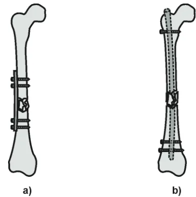
Internal Fixation of Fractures. Here we present two of the solutions of internal fracture fixation using: neutralization plate and intramedullary nail.
Fig. 1. Solutions for fractures of long bones. a) Neutralization plate.; b) Intramedullary nail.
Intramedullary Nail. In the long tubular bone very effective fracture stabilization can be achieved by some of intramedullary devices, such is intramedullary nail (Fig 1.b).
The stability of fracture fixation by nailing mainly depends on the mechanical properties of the nail, the nail’s fit in the medullary space, and the mechanical properties of the locking screws or bolts. The bending and torsional stiffness of the nailed bone mainly depends on the diameter of the nail.
4. FE modeling of femur comminuted fracture
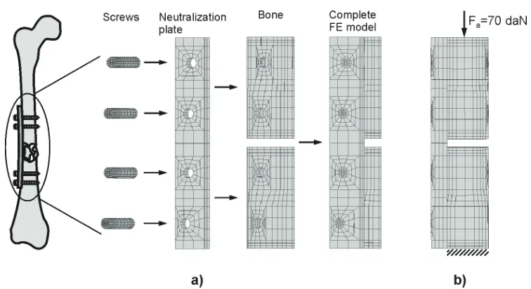
During walk human alternately stands on each leg with the whole weight. Hence, at the moment of standing on one leg, the axial force in the leg is equal to the human weight. In this study we consider a patient with body mass of 70 [kg], having diaphysial comminuted fracture. Assumed body mass of 70 [kg] induces the axial force of 70 [daN] in the material of femoral bone.
4.1. Fixation by the neutralization plate
Fig. 2. a) Finite element model of femur comminuted fracture fixed by neutralization plate. b) Boundary condition and load. The load is transferred from the upper bone fragment to the upper
set of screws, then by the plate to the lower set of screws and the lower bone fragment.
The bone tissue is modeled using the material model defined by the relation (1). The solution is obtained using the following data for the bone tissue:
3
22.1 10
c
E = ⋅ MPa, ρ =2.1 10⋅ −3g mm/ 3, 1.8 10 3 / 3
c g mm
ρ = ⋅ − , e=0.1s−1
&
where it is assumed that the strain rate is the same within the tissue. For the neutralization plate and screw materials the stainless steel is used, with Young's modulus E=2.1 10⋅ 5
[
MPa]
andPoisson's ratio ν =0.3.
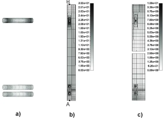
Fig. 3. FE solution forthe femur comminuted fracture. Effective stress field within: a) Screws;
b) Neutralization plate; c) Bone tissue.
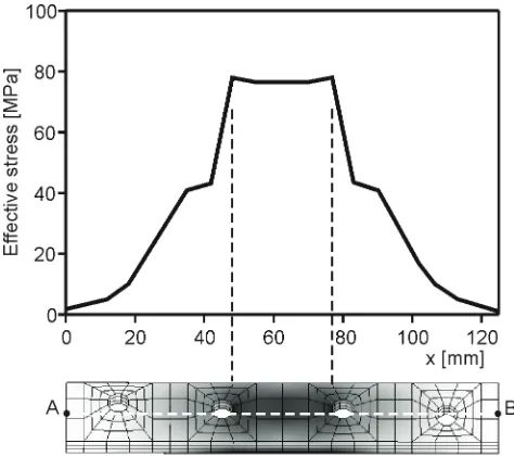
Fig. 4. Distribution of the effective stress within the neutralization plate along the line AB.
4.2. Fixation by the intramedullary nail
The femoral shaft fracture fixed by an interlocking nail is modeled. In this particular case we assume comminuted type of fracture. Also, it is taken that the intramedullary nail is locked by two screws proximally and two screws distally.
elements) and loading as is in the previous example. For the intramedullary nail material the stainless steel is taken, with the characteristics as for neutralization plate and screw. The finite element model is shown Fig. 5.
Fig. 5.a) Finite element model of the femur comminuted fracture fixed by intramedullary nail.
b) Boundary condition and load. The load is transferred from the upper bone fragment to the upper screw, then by the intramedullary nail to the lower set of screws and the lower bone
fragment.
The field of effective stress in the screws, intramedullary nail and bone is shown in Fig. 6. Also, distribution of the effective stress within the intramedullary nail along the line AB is shown in the Fig. 7.
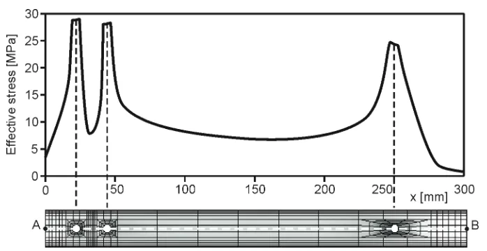
Fig. 7. Distribution of the effective stress within the intramedullary nail along the line AB.
4.3. Discussion
It can be noted from Figs. 3 and 4 that a significant stress elevation (stress concentration) appears within the neutralization plate in the region between second and third screw. The extreme values of effective stress are below the critical values for stainless steel. However, the neutralization plate is subjected to the cycling loading during the walk which leads to the material fatigue. The region between the second and third screw is critical (locus minoris resistentiae) for the fatigue failure, which is frequently observed in clinical practice[5].
On the other hand, in the case of intramedullary nail application, notable stress concentration occurs within the intramedullary nail in the region of the screw holes (Figs. 6 and 7). But these values are appreciably lower than the effective stress generated in the neutralization plate for the same loading conditions. Hence, the risk of intramedullary nail failure is significantly lower than it is in when using the neutralization plate, which also is clinically approved [5].
Presented results explicitly indicate advantages of application of intramedullary nail compared to neutralization plate regarding to fixation stability. Solutions for other bone fractures and modeling of these solutions are given in [6].
Acknowledgments
This study is partly supported by Ministry of Science and Environmental Protection of Serbia, projects TR6209 and OI144028, and City of Kragujevac.
References
[1] Carter DR, Hayes WC (1977). The compressive behavior of bone as a two-phase porous structure, J. Bone Joint Surgery, 59, 954-962.
[2] Huiskes R, Van Rietbergen B (2005). Biomechanics of bone. In: Basic Orthopaedic Biomechanics and Mechano-Biology. edited by Mow VC, Huiskes R, 3rd edition,
[3] Kojic M, Slavkovic R, Zivkovic M, Grujovic N (1998). The Finite Element method-Linear Analysis. (in Serbian) Faculty of Mech. Engrg., Univesity of Kragujevac, Serbia.
[4] Kojic M., Slavkovic R., Zivkovic M., Grujovic N., Filipovic N., PAK – Finite Element Program for Linear and Non-linear Structural Analysis, Mass and Heat Transfer and Biomechanics, Faculty of Mechanical Engineering, University of Kragujevac, 1996. [5] Bucholz RW, Brumback RJ (1991). Fractures of the shaft of the femur. In: Fractures
in adults. edited by Rockwood CA, Green DP, Bucholz RW, 3rd edition, 2, 1653-1724,
JB Lippincott, New York.