IJIRT 144998
INTERNATIONAL JOURNAL OF INNOVATIVE RESEARCH IN TECHNOLOGY169
ENHANCED DIGITAL DOOR LOCK SECURITY
SYSTEM BY USING RFID & GSM
Shaik Shafiya1, Parachoori Sai Krishna2
1Assistant Professor, Nalla Narasimha Reddy Group Of Institutions, Hyderabad 2Assistant Professor, Sree Rama Institute Of Technology And Science, Kuppenakuntla
Abstract- This paper gives the design and implementation of GSM based digital door lock security system. Here to lock and unlock the door by using a motor a 5 digit password was used. After 3 unsuccessful trails the system gives a warning message to the preset mobile number. Here to control the system a separate arrangement was installed. In the same way to implement and demonstrate the proposed system, a 3D scaled model of a house controlled by a gear motor was constructed. Result of proposed security system was stable.
I.INTRODUCTION
The main purpose of security system is to protect homes from burglary and security describes the protection and property. There are different types of modes in security system they are key locks and chains. Basically, in 2010 the FBI which is nothing but the Federal Bureau of Investigation says that more than two million home burglaries took place in United States. In that 70 percent burglaries took place in residential homes. Coming to 2011 the NCRB (i.e.) National Crime Records Bureau says that 58862 cases were registered in India with worth of USD 50 million .Next coming to the research of AIREF (Alarm Industry Research and Educational Foundation), they says that most of the burglars spend 60 seconds for breaking a home. So to overcome all these problems The Electronic Security Association (ESA) of the “home safety fast facts” report says that if they encountered the alarm there is a possibility that they would not attack the home. Now there is a chance to drop the attempt. From this there is huge encouragement to develop the security systems both in commercial and residential applications. Basically this security alarm system consists of various sensors for operating and detecting.
Now, Mallory et al. developed a security alarm system with number of sensors for following operations (fire, smoke, intrusion and appliance). To monitor the system a central monitor was provided, this central monitor gives continuously the status of sensors. For effective communication transmitters are placed on the sensors and receivers are placed on the monitors. Depending upon the transmitter of particular sensor the central alarm shows the appropriate alarm.
This is about Mallory coming to Murakami et al, he also developed a security system but the main difference is that here the number of sensors will detect an alarming situation in different locations. Now at the same time the cameras capture the images of different locations and the controller registers the association between sensors and cameras. Similarly, Pyle et al. also developed a security system in this the system altered an intrusion disturbance at the starting point by producing an alarm.
IJIRT 144998
INTERNATIONAL JOURNAL OF INNOVATIVE RESEARCH IN TECHNOLOGY170
design which consists of so many modules and eachmodule is made up of discrete components that are joined together. To obtain the desired result all the units should function together.
In the same way the SMS technology was mixed with GSM/GPRS services to obtain the controlling of door lock. Now in this paper we will discuss the design and implementation of the PIC supported security system prototype with 5 digit password. In this society the influential persons use the bullet proof doors for better security. All these security systems are used in corporate offices and automated machines and home security.
II. COMPONENTS
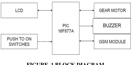
The below figure (1) shows the block diagram of security system. There are 6 blocks/components in the block diagram they are PIC 16F877A, GSM module, Buzzer, Gear motor, switches. Now let us discuss the each component in detail manner.
Microcontroller PIC 16F877A
In microchip, it is a 40 pin 8 bit CMOS FLASH microcontroller. Here it is followed by RISC architecture, it means all single cycle instruction takes as cycle instructions but for program branches it takes two cycles. PIC 16F877A consists of three operating speeds with 4, 8 or 20MHZ clock input. But in this we use 20MHZ crystal oscillator. This crystal oscillator is fed through the two ports (i.e.) OSC1 and OSC2 ports. The ports 11 and 32 are shorted and the ports 12 and31 are grounded and +5v is given for working of PIC.
GSM Module
The below figure (2) shows the GSM SIM300 module. It consists of five 6 ports they are input port, antenna, TX Rx port, buzzer, SIM slot and serial port.
The main function of the GSM module is that it acts as both transmitting and receiving unit that employs the use of mobile phone set serving and it is the communication device between user at one end and object at other end. The features of GSM SIM300 are given below
1. The Operating Voltage: 7 – 15V AC or DC 2. For easy and direct interface to
microcontroller and arduino controller it provides serial transistor transistor logic. 3. The SIM300 allows an adjustable serial
baud rate from 1200 to 115200 bps.
The GSM is given as global system for mobile communication and it was developed by the European Telecommunications Standards Institute (ETSI). The main purpose is to describe the protocols for second-generation (2G) digital cellular networks which are used by mobile phones. As discussed earlier that GSM module is interfaced with PIC for sending warning message. Here the port 25 is the transmitter port of PIC which is inter linked with GSM module. Coming to the receiver port of PIC is interlinked with the same GSM module and ground port of GSM is grounded.
The below figure (3) shows the connection diagram of GSM module. In this first the owner sends a message from GSM mobile to GSM kit which is connected to the arduino controller. Now the arduino controller gives a command to the servo motor to open or close the door lock as per given password. If the password is detected then the arduino controller stars the buzzer and sends a warning message. If it works with GSM network then owner can receive the message at remote location.
FIGURE .1 BLOCK DIAGRAM
IJIRT 144998
INTERNATIONAL JOURNAL OF INNOVATIVE RESEARCH IN TECHNOLOGY171
16 x 2 LCD displayThe below figure (4) shows the 16×2 LCD display. The main purpose is for displaying the password as well as detecting the wrong password. The pins are explained in detail manner as shown below.
The JHD162A 16 x 2 LCD consists of 16 pins and it operates in both 4 bit mode and 8 bit mode. But for LCD module we use 4 bit mode. Now the pins of the JHD162A LCD module are given as; Pin 1 (VSS) is the ground pin of LCD module. Coming to the Pin 2 (VCC) it gives the supply voltage of +5v. Pin 3 (VEE) gives the contrast adjustment, it is done by the connecting ends to +5v & ground and connecting the slider pin to VEE.. coming to pin 4 (RS) it is a register
select pin but there are two types of register select pins one is command register and another one is data register. If we select the data register pin then the logic is high at RS pin and if we select the command register then the logic is low at RS pin. If we make RS high then we put data on the data lines so that it will recognizes the data and In the same way if we select RS pin is low then we put data on the data lines then it will selects the command.
Pin 5 (R/W) gives the read and write operation. If the logic is high then the pin activates the read operation
and if the logic is low then the pin activates the write operation. Coming to pin 6 (E), it is for enabling the module from high to low signal and pin 7 (DB0) to pin 14 (DB7) are the data pins where command and data are put on this pins. Pin 11,12,13,14 of LCD module are interlinked through ports 35, 363, 37, 38.
Buzzer
Basically buzzer is an element of piezoelectric and it is driven by oscillating electronic circuit. After driven through an electronic circuit it driven from the piezoelectric audio amplifier. The main purpose is to indicate that a button has been pressed. In this the signal to buzzer is given through the port 28 of PIC. Now this is connected to the positive terminal of buzzer.
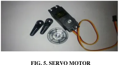
Gear Motor/Servo Motor
For controlling the door lock we use gear motor. The gear motor is also called servo motor. The main function of servo motor is to operate the door lock key to open or close the door lock. To open or close the door arduino controller gives a command; the key motor of this rotates in clockwise and anti clockwise direction. Now to open the lock we use password 1234 and to close the lock we use password 4321 for all the three modules. The stepper motor is operated in reverse direction and the door gets locked again. The below figure (5) shows the servo motor.
Switches
In this we use push switches. The main purpose behind using the push switches is to lock, unlock and password change commands. Basically the password switches are connected to 15,16,17,18 and 23 ports of PIC. We use different pins to lock, unlock and password change commands. For locking purpose the FIG. 4. 16×2 LCD DISPLAY
IJIRT 144998
INTERNATIONAL JOURNAL OF INNOVATIVE RESEARCH IN TECHNOLOGY172
switch is connected to the pin 21 and for unlockingpurpose the switch is connected to the pin 22 and finally for password changing the switch is connected to 27.
III. PROPOSED SYSTEM
Up to now we have discussed that the security system uses only function keys to operate. Now in existed system the security is obtained by using RFID, IR and image capture sensor. It means we use RFID sensor instead of function key to open the door. From this we can observe that the door will be opened for the authorized persons. If UN authorized persons used to open this door then it will gives an alarm sound as well as the image capture sensor gets pictorial information. The advantage of this one is we can send this information through the mail. Now by using the IR sensor we can find out the unwanted entries as well as we can get an alert through buzzer and present status information is obtained through the GSM. The below figure (6) shows the proposed system.
IV. RESULTS
The below figure (7) shows the digital security system. In this all the components which we have studied earlier plays their major role and obtains specified output.
IV. CONCLUSION
The GSM based digital door lock system was proposed and implemented successfully. By using the different combination passwords number of trails has been done. In this the dedicated power supply helps the system to provide a fluctuation free service. This type of security systems are used in both residential and commercial applications. Here all the modules provide a security alert with buzzer alarm and SMS facility to the owner. Because of this it is very useful to avoid the unwanted entries. From the proposed system we can observe that RFID, IR and image captured sensors are used for the purpose of security and it gives the best result compared to previous security system.
REFERENCES
[1] J. Thong and N. Nicolici, “An optimal and practical approach to single constant multiplication,” IEEE Trans. on Computer-Aided Design of Integrated Circ. And Systems, vol. 30, no. 9, pp. 1373-1386, Sep. 2011.
[2] L. Aksoy, E. da Costa, and P. Flores, “Exact and Approximate Algorithms for the Optimisation of Area and Delay in Multiple Constant Multiplication,” IEEE Trans. on Computer-Aided Design of Integrated Circuits and Systems, vol. 27, no. 6, pp. 1013-1026, June 2008.
[3] A.K. Oudjida and N. Chaillet, “Radix-2r Arithmetic for Multiplication by a Constant,” IEEE Trans. on Circuits and Systems II: Express Brief, vol. 61, no 5, pp. 349-353, May 2014.
FIG. 6 . PROPOSED SYSTEM
IJIRT 144998
INTERNATIONAL JOURNAL OF INNOVATIVE RESEARCH IN TECHNOLOGY173
[4] A.K. Oudjida, N. Chaillet, and M.L. Berrandjia,“Radix-2r Arithmetic for Multiplication by a Constant: Further Results and Improvements,” IEEE Trans. On Circuits and Systems II: Express Brief, vol. 62, no. 4, pp. 372-376, April 2015.
[5] A. Avizienis, “Signed-digit number representation for fast parallel arithmetic,” IRE Trans. on Electronic Computers, vol. EC-10, No. 3, pp. 389–400, September 1961.
[6] R.L. Bernstein, “Multiplication by Integer Constant,” Software– Practice and Experience 16, 7, pp. 641-652, 1986.
[7] V. Lefèvre, “Multiplication by an Integer Constant,” INRIA Research Report, No. 4192, Lyon, France, May 2001.
[8] A.G. Dempster and M.D. Macleod, “Use of Minimum Adder Multiplier Blocks in FIR Digital Filters,” IEEE Trans. on Circuits and Systems-II: Analog and Digital Signal Processing 42, 9, pp. 569-567, 1995.
[9] Y. Voronenko and M. Püschel, “Multiplierless Multiple Constant Multiplication,” ACM Trans. on Algorithms (TALG), vol. 3, No. 2, article 11, pp. 1-38, May 2007.